Table of Contents
Advertisement
Quick Links
Instructions for Final Assembly
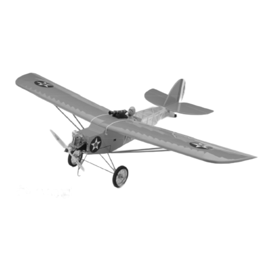
Commemorate the Aviation's beginnings with the new Global Blue Max ARF.
A time when the nose skid was as important as the tail skid to safety minded
pilots landing on unprepared airfields, planes of this style used cutting edge
technology for their day. The Blue Max remembers those years long past. It's
open cockpit, wire spoke wheels and open framework capture a more experi-
mental time in aviation. The high lift wing and generous wing area mean
super slow stall speed and very forgiving flight characteristics. Don't be sur-
prised if you see beginners with this plane. Our test pilots say this plane is
easier to fly than most .40 size trainer planes. And unlike the grossly under-
powered airplanes of yesteryear, the Blue Max is favorably powered using a
.40 size two stroke or a .52 size four stroke. So put on your scarf and your
goggles and get ready to go back into time. Oh, and don't forget to load that
cannon!
Version V1.0
4-99
Kit # 232500
All Contents © Copyright 1999
1
Advertisement
Table of Contents

Summary of Contents for Blue Max Global Arf
- Page 1 A time when the nose skid was as important as the tail skid to safety minded pilots landing on unprepared airfields, planes of this style used cutting edge technology for their day. The Blue Max remembers those years long past. It's open cockpit, wire spoke wheels and open framework capture a more experi- mental time in aviation.
-
Page 2: Table Of Contents
Kit Contents...........3 Fuel Tank............13 Additional Items Required........3 Fuel Tank Assembly........13 Tools and Supplies Needed......3 Fuel Tank Installation.......13 Field Support Equipment Needed......3 Throttle Linkage..........14 Metric Conversion Chart.........3 Installing the Throttle Linkage....14 Wing Assembly..........4 Servo Installation...........14 Installing the Fuselage Servo Tray....14 Install the Dihedral Braces......4 Installing the Aileron Servo Tray....14 Joining the Wing Halves......5 Installing the Aileron Servo......15... -
Page 3: Kit Contents
This instruction manual is designed to help you build a straight, great flying airplane. Please read this manual thoroughly before beginning assembly of your new Blue Max. Use the parts listing below to identify and separate all parts before beginning assembly. -
Page 4: Additional Items Required
{1}Hitec 4 or More Channel Radio w/4 Servos FOR 4-STROKE ENGINE {1}Dubro Foam Rubber # 513 {1}Magnum XL .52RFS Four Stroke {1}Global Fuel Line # 115923 {1}Magnum 1/4” Spinner Nut # 237310 {1}Arco # 64 Rubber Bands # 24649 {1}Propeller To Suit Engine FOR 2-STROKE ENGINE {1}Thunderbolt Glow Plug # 115490 {1}Magnum XL .40-.46 Two Stroke... -
Page 5: Wing Assembly
**NOTE** Please trial fit all the parts. Make sure you have the correct parts and that they fit and are aligned properly before gluing! This will assure proper assembly. Since the Blue Max is hand made from natural materials, every plane is unique and minor adjustments may have to be made. However, you should find the fit superior and assembly simple. -
Page 6: Joining The Wing Halves
JOINING THE WING HALVES 6) Mix a generous amount of Kwik Bond PARTS REQUIRED 30 Minute Epoxy. Working with only one wing {1} Fuselage half for now, apply a thin layer of epoxy inside {2} Wing Hold Down Dowels (W-43) both dihedral brace boxes and on only half of {2} Wing Struts each dihedral brace. -
Page 7: Aligning The Wing To The Fuselage
ALIGNING THE WING TO THE FUSELAGE Photo # 9 5) Using a ruler and a pen, locate and mark the centerline of the fuselage at both the front and REMOVE COVERING AILERON rear of the wing saddle. Place a mark at both locations. -
Page 8: Mounting The Horizontal Stabilizer
2) Using a ruler and a pen, locate and mark Figure # 1 the centerline of the horizontal stabilizer at the trailing edge and place a mark. Use a triangle and extend this mark, from back to front, across the bottom of the stabilizer. Also place center- line marks on the top of the stabilizer at the leading and trailing edges only. -
Page 9: Vertical Stabilizer Mounting
8) When you are satisfied that everything is 4) Set the vertical stabilizer back in place. aligned correctly, mix up a generous amount of Using a triangle, check to ensure that the vertical Kwik Bond 30 Minute Epoxy. Apply a thin layer stabilizer is aligned 90º... -
Page 10: Hinge The Elevator
2) When satisfied with the fit, remove the ai- 7) With the elevator tight against the stabi- leron and slide a small piece of waxed paper be- lizer, rotate the elevator down about 45º. Apply tween the aileron torque rod and the trailing edge six drops of Kwik Bond Thin C/A to the exposed of the wing. -
Page 11: Mounting The Tail Wheel Bracket
13) With the rudder tight against the stabi- lizer, rotate the rudder to one side about 45º. Ap- PARTS REQUIRED ply six drops of Kwik Bond Thin C/A to the ex- {1} Wire Main Gear Assembly posed area of each hinge. Allow the glue to cure {2} Nylon Mounting Straps w/4mm Slot for about ten minutes. -
Page 12: Installing The Main Gear Wheels
6) Secure the gear assembly in place by in- 3) When satisfied with the alignment of the stalling the eight 3mm x 12mm wood screws engine, remove the beams from the clamp and through the mounting straps and remove the drill 1/8”... -
Page 13: Mounting The Engine To Firewall
7) With your engine still installed on the mo- Photo # 26 tor mount beams, use a ruler and measure the width between the predrilled mounting holes in the motor mount beams. This distance will vary depending on the brand and size of the engine you have cho- sen. -
Page 14: Fuel Tank
5) Secure the nose skid in place by install- 4) Carefully bend the longer of the two tubes ing the six 3mm x 12mm wood screws through up at a 45º angle. This tube is the vent tube. the mounting straps and remove the masking tape. When the stopper assembly is installed in the tank, See photo # 28 below. -
Page 15: Throttle Linkage
10) Secure the fuel tank in place using sev- 2) Remove the servos from the servo tray. eral pieces of foam rubber. Seal any gaps be- Using a ruler and a pen, locate and mark the po- tween the stopper assembly and the firewall us- sition of the four servo tray mounting holes on the ing silicon sealer. -
Page 16: Installing The Aileron Servo
8) Place the servo tray, with the aileron servo, INSTALLING THE FUSELAGE SERVOS into the precut opening in the bottom of the wing. 13) Install the three fuselage servos using The servo should be orientated with the output shaft the wood screws provided with your radio sys- towards the trailing edge of the wing. -
Page 17: Rudder Pushrod
3) Slide the adjustable servo connector/ Figure # 6 throttle arm assembly over the end of the throttle pushrod wire. Position the throttle stick and the MACHINE throttle trim at their lowest positions. SCREW CONTROL HORN RUDDER 4) Manually push the carburetor barrel fully closed. -
Page 18: Elevator Pushrod
8) Use a couple of pieces of masking tape towards the pushrod exit in the fuselage side. See to hold the rudder in neutral. figure # 7 below. Figure # 7 9) Locate a long servo arm. Using wire cut- ters, remove all but one of the arms. -
Page 19: Aileron Linkage
8) Use a couple of pieces of masking tape Figure # 8 to hold the elevator in neutral. ADJUSTABLE CONTROL HORN 9) Locate a long servo arm and using wire 7/8” TORQUE cutters, remove all but one of the arms. Install the Z-bend in the 1.5mm x 50mm wire into the outer hole in the servo arm. -
Page 20: Pilot And Cannon
5) Test fit the seat back onto the barrel seat, inside the fuselage. Using a pen place marks on the seat back where the pushrod tubes contact PARTS REQUIRED it on either side. Remove the seat back and cut {1} Prepainted Balsa Cannon Mount out only those areas that interfere with the push- {2} Plastic Body Halves rod tubes. -
Page 21: Barrel Seat Installation
11) After the glue has completely cured, trial PILOT INSTALLATION fit each of the halves together. Make any adjust- 17) Roughen the bottom of the head and the ments necessary to get each half to fit as close as top of the body using 220 grit sandpaper. Using possible. -
Page 22: Final Assembly
Max to be more stable, but less responsive. Do the fuel pickup tube at the tank and to the fuel not fly the Blue Max beyond the recom- nipple on the carburetor. The second piece should mended balance range or an uncontrollable... -
Page 23: Lateral Balance
LATERAL BALANCE After you have balanced the Blue Max on 1) Check the operation and direction of the the C.G. you must laterally balance it. Do- ing this will help the airplane track better. elevator, rudder, ailerons and throttle. 1) Turn the airplane upside down. Attach... -
Page 24: Preflight Check
Choosing the Blue Max greatly simplifies these trol surface hinges as well. activities. First, it takes very little thrust to over- come the drag. So much so that the Blue Max 3) Double check the balance of the airplane. glides with no power at all. - Page 25 If you can easily steer the Blue Max around on Now try a turn (before the airplane gets too far the ground, it's time to take that experience and away).
- Page 26 The descent should be gentle so let the nose drop If the plane seems too fast or getting into too about 10 to 20 degrees. Keep the wing level steep a turn, try letting all the controls go to unless a turn is required. If you must turn, bank neutral, then reduce the throttle and make usual to start the turn but only hold about half of corrections to level the wings and then level...
-
Page 27: Product Evaluation
Simply fold this form on the dotted lines, seal with tape and mail it to us. Do not use staples and make sure our address faces out. 1.) Kit: Blue Max (#232500) 7.) Was any of the model's assembly difficult for you? If yes, please explain. - Page 28 Place Stamp Here Global Hobby Distributors Attn: Customer Service Department 18480 Bandilier Circle Fountain Valley, CA. 92728 Fold along dotted line...
Need help?
Do you have a question about the Global Arf and is the answer not in the manual?
Questions and answers