Table of Contents
Advertisement
Available languages
Available languages
Advertisement
Table of Contents
Troubleshooting

Related Manuals for Mini-Itx P55-T36

Summary of Contents for Mini-Itx P55-T36
-
Page 1: System Board
System Board User’s Manual 935-MP55T1-000G 12310953E-DVD... -
Page 2: Fcc And Doc Statement On Class B
Copyright This publication contains information that is protected by copyright. No part of it may be reproduced in any form or by any means or used to make any transfor- mation/adaptation without the prior written permission from the copyright hold- ers. -
Page 3: Table Of Contents
Table of Contents About this Manual ...................4 Warranty ......................4 Static Electricity Precautions .................5 Safety Measures ....................5 About the Package ..................6 About the Genie BIOS Guideline ..............6 Before Using the System Board ..............6 System Board Layout ..................7 English ......................... 8 Français ......................31 Deutsch ......................54 Italiano ......................77... -
Page 4: About This Manual
English About this Manual An electronic file of this manual is included in the DVD. To view the user’s man- ual, insert the DVD into an optical drive. The autorun screen will appear. On the top row of the screen, click the last icon to open the Manuals menu. For additional information on the system board, please download the complete version of the manual from DFI’s website. -
Page 5: Static Electricity Precautions
English Static Electricity Precautions It is quite easy to inadvertently damage your PC, system board, components or devices even before installing them in your system unit. Static electrical dis- charge can damage computer components without causing any signs of physical damage. -
Page 6: About The Package
English About the Package The system board package contains the following items. If any of these items are missing or damaged, please contact your dealer or sales representative for as- sistance. One system board Four Serial ATA data cables ... -
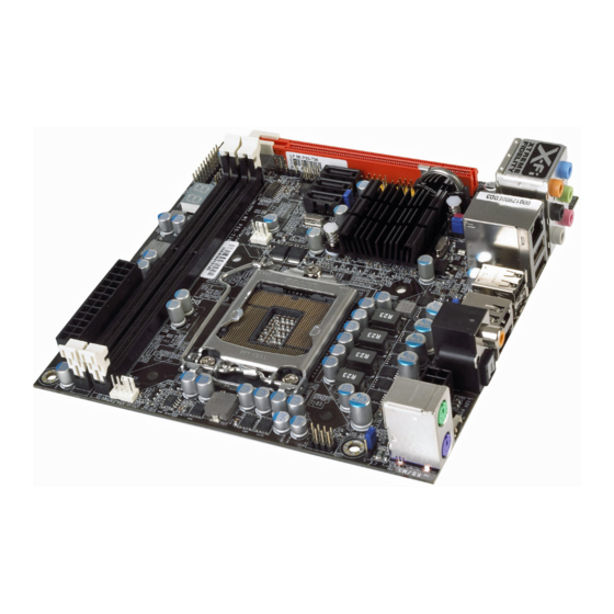
Page 7: System Board Layout
English System Board Layout CPU fan power Mouse PS/2 power select (J Clear CMOS switch LGA 1156 12V power S/PDIF- Top: Coaxial RCA Bottom: Optical Top: USB 10 Bottom: Port shared DRAM between Power eSATA power LED and USB 11 USB 8-13 power select (JP5) -
Page 8: English
English Chapter 1 - Introduction Specifications Processor • LGA 1156 socket for: - Intel Core i5/i7 Lynnfield processors ® • Supports Intel Turbo Boost Technology ® Chipset • Intel P55 Express chipset ® System Memory • Two 240-pin DDR3 DIMM sockets •... - Page 9 • Monitors the speed of the cooling fans • CPU Overheat Protection function monitors CPU tempera- ture and fan during system boot-up - automatic shutdown upon system overheat • 6 layers, Mini-ITX form factor • 17cm (6.7”) x 17cm (6.7”)
-
Page 10: Jumper Settings
English Chapter 2 - Hardware Installation Jumper Settings Clear CMOS Data Clear CMOS switch 1-2 On: Normal (default) 2-3 On: Clear CMOS Data If you encounter the following, a) CMOS data becomes corrupted. b) You forgot the supervisor or user password. c) The overclocked settings in the BIOS resulted to the system’s instability or caused system boot up problems. - Page 11 English PS/2 Power Select 1-2 On: 5V 2-3 On: 5VSB (default) Selecting 5VSB will allow you to use the PS/2 keyboard or PS/2 mouse to wake up the system. Important: The 5VSB power source of your power supply must support ≥720mA.
- Page 12 English USB Power Select USB 8-13 (JP5) 1-2 On: 5V 2-3 On: (default) 5VSB USB 0-3 (JP6) 2-3 On: 1-2 On: 5V 5VSB (default) Selecting 5VSB will allow you to use the USB keyboard to wake up the system. Important: The 5VSB power source of your power supply must support ≥1.5A (2 devices) or ≥2A (3 or more devices).
- Page 13 English Secondary RTC Reset JP12 1-2 On: Normal 2-3 On: (default) RTC Reset When the RTC battery is removed, this jumper resets the manageability register bits in the RTC. Note: 1. The SRTCRST# input must always be high when all other RTC power planes are on.
- Page 14 English PS/2 Ports and S/PDIF Ports PS/2 Mouse PS/2 KB Coaxial RCA S/PDIF Optical S/PDIF SPDIF out Ground SPDIF in S/PDIF PS/2 Mouse and PS/2 Keyboard Ports These ports are used to connect a PS/2 mouse and a PS/2 keyboard. Optical S/PDIF The optical S/PDIF jack is used to connect an external audio output device using an optical S/PDIF cable.
- Page 15 English Power eSATA Power eSATA Port shared between Power eSATA and USB 11 The arrow above points to the location shared by the Power eSATA and USB 11. You can choose to plug a Power eSATA device or a USB device. This port supplies sufficient power to run an eSATA device (no additional power required).
- Page 16 English USB and LAN Ports USB 10 USB 11 / Power eSATA USB 9 USB 8 USB 12 USB 2-3 USB 13 USB 0-1 The USB ports are used to connect USB 2.0/1.1 devices. The 10-pin connectors allow you to connect 4 additional USB 2.0/1.1 ports. Your USB ports may come mounted on a card-edge bracket.
-
Page 17: Speaker
English Audio and CD-In Rear audio Center/ Line-in Subwoofer Front R/L Rear R/L Mic-in Side R/L CD-in Ground Ground Left audio Right audio Front audio channel channel Rear Panel Audio • Center/Subwoofer Jack (Orange) This jack is used to connect to the center and subwoofer speakers of the au- dio system. - Page 18 English • Line-out - Front Right/Left Jack (Lime) This jack is used to connect to the front right and front left speakers of the audio system. • Mic-in Jack (Pink) This jack is used to connect an external microphone. Front Audio The front audio connector is used to connect to the line-out and mic-in jacks that are at the front panel of your system.
-
Page 19: Irda Connector
English IrDA Connector IRRX N. C. Ground IRTX Connect the cable connector from your IrDA module to the IrDA connector. Note: The sequence of the pin functions on some IrDA cable may be reversed from the pin function defined on the system board. Make sure to connect the cable to the IrDA connector according to their pin functions. - Page 20 English Cooling Fan Connectors CPU fan Ground Speed Control Power Sense PWM fan Ground Sense Power These fan connectors are used to connect cooling fans. Cooling fans will provide adequate airflow throughout the chassis to prevent overheating the CPU and sys- tem board components.
- Page 21 English LEDs DRAM Power LED Diagnostic LED Standby Power LED DRAM Power LED This LED will light when the system’s power is on. Standby Power LED This LED will light when the system is in the standby mode. Diagnostic LED The Diagnostic LED displays POST codes.
-
Page 22: Power Connectors
English Power Connectors Use a power supply that complies with the ATX12V Power Supply Design Guide Version 1.1. An ATX12V power supply unit has a standard 24-pin ATX main power connector that must be inserted into this connector. 12 24 +3.3VDC +5VDC +12VDC... - Page 23 English The power connectors from the power supply unit are designed to fit the 24-pin and 8-pin connectors in only one orientation. Make sure to find the proper orien- tation before plugging the connectors. The system board requires a minimum of 200 Watt power supply to operate. Your system configuration (CPU power, amount of memory, add-in cards, peripherals, etc.) may exceed the minimum power requirement.
-
Page 24: Pwr-Led
English Front Panel Connectors SPEAKER RESET ATX-SW HD-LED PWR-LED HD-LED: Primary/Secondary IDE LED This LED will light when the hard drive is being accessed. RESET: Reset Switch This switch allows you to reboot without having to power off the system thus prolonging the life of the power supply or system. - Page 25 English PWR-LED: Power/Standby LED When the system’s power is on, this LED will light. When the system is in the S1 (POS - Power On Suspend) or S3 (STR - Suspend To RAM) state, it will blink every second. Note: If a system did not boot-up and the Power/Standby LED did not light af- ter it was powered-on, it may indicate that the CPU or memory module was not installed properly.
- Page 26 English PCI Express Slot PCIE 1 Download Flash BIOS Connector...
- Page 27 English Smart Connectors The Smart Connectors (USB, Front Panel) serve as extended connectors allowing you to easily connect cables to the connectors that are on the system board. This is specially advantageous when using the front panel connectors as this will pre- vent wrong cable connection.
-
Page 28: Raid Levels
English Chapter 3 - RAID The Intel chip allows configuring RAID on Serial ATA drives. It supports RAID 0, RAID 1, RAID 0+1 and RAID 5. RAID Levels RAID 0 (Striped Disk Array without Fault Tolerance) RAID 0 uses two new identical hard disk drives to read and write data in parallel, interleaved stacks. - Page 29 English Settings To enable the RAID function, the following settings are required. 1. Connect the Serial ATA drives. 2. Configure Serial ATA in the AMI BIOS. 3. Configure RAID in the RAID BIOS. 4. Install the RAID driver during OS installation. 5.
- Page 30 English Step 4: Install the RAID Driver During OS Installation The RAID driver must be installed during the Windows XP or Windows 2000 in- ® ® stallation using the F6 installation method. This is required in order to install the operating system onto a hard drive or RAID volume when in RAID mode or onto a hard drive when in AHCI mode.
-
Page 31: Français
Français Chapitre 1 - Spécifications Processeur • LGA 1156 socket pour: - Intel Core i5/i7 Lynnfield ® • Prend en charge la technologie Turbo Boost d’Intel ® Chipset • Intel P55 Express ® Mémoire Système • 2 sockets DIMM DDR3 240-pin •... - Page 32 • Gère la vitesse de ventilateur du ventilateur • Protection du CPU - supporte la mise hors circuit automa- tique en cas de surchauffage du système • 6 layers, facteur de forme de Mini-ITX • 17cm (6.7”) x 17cm (6.7”)
- Page 33 Français Chapitre 2 - Installation de Matériel Cavalier Effacer les Données CMOS Clear CMOS switch 1-2 On: Effacer les données CMOS 2-3 On: Clear CMOS Data 2-3 On: Effacer les données CMOS Si vous rencontrez les éléments suivants, a) Données CMOS devenant corrompues b) Vous avez oublié...
- Page 34 Français Sélectionner l’alimentation PS/2 1-2 On: 5V 2-3 On: (défaut) 5VSB En sélectionnant 5VSB, vous pourrez utiliser le clavier PS/2 ou la souris PS/2 pour “réveiller” le système. Important: La source d’alimentation 5VSB de votre alimentation doit supportée ≥720mA.
- Page 35 Français Sélectionner l’alimentation USB USB 8-13 (JP5) 2-3 On: 1-2 On: 5V 5VSB (défaut) USB 0-3 (JP6) 1-2 On: 5V 2-3 On: (défaut) 5VSB En sélectionnant 5VSB, vous pourrez utiliser le clavier USB pour “réveiller” le système. Important: La source d’alimentation 5VSB de votre alimentation doit supportée ≥1,5(2 ports) ou ≥2 A(3 ou davantage de ports).
- Page 36 Français Réinitialisation de l’horloge temps réel secondaire JP12 1-2 On: Normal 2-3 On: (défaut) RTC Reset Lorsque la pile de l’horloge est enlevée, ce cavalier réinitialise la capacité de ges- tion des octets du registre de l’horloge. Note: 1. L’entrée SRTCRST# doit toujours être élevée lorsque toutes les au- tres couches Power plane de l’horloge sont ON.
- Page 37 Français Ports PS/2 et S/PDIF Souris PS/2 Clavier PS/2 Coaxiale de RCA S/PDIF Optique S/PDIF SPDIF out Ground SPDIF in S/PDIF Ports Souris PS/2 et Clavier PS/2 Ces ports sont utilisés pour raccorder une souris PS/2 et un clavier PS/2. Prises Coaxiale de RCA S/PDIF et Optique de S/PDIF Ces prises sont utilisées pour connecter les appareils de sortie audio externes en utilisant les câbles coaxiaux et optique S/PDIF.
- Page 38 Français Port Power eSATA Power eSATA Port partagé par l’Alimentation eSATA et l’USB 11 La flèche ci-dessus montre l’emplacement partagé par l’eSATA d’alimentation et USB 11. Vous pouvez choisir de brancher, soit un périphérique d’alimentation eSATA, soit un dispositif USB. Ce port fournit l’énergie suffisante pour actionner un périphérique eSATA (pas besoin d’alimentation externe).
- Page 39 Français Ports USB et LAN USB 10 USB 11 / Power eSATA USB 9 USB 8 USB 12 USB 2-3 USB 13 USB 0-1 Ports USB Les ports USB sont utilisés pour raccorder des appareils USB 2.0/1.1. Les con- necteurs 10 broches vous permettent de raccorder 4 autres ports USB 2.0/1.1. Vos ports USB peuvent être livrés montés sur un support encartable.
- Page 40 Français Audio et CD-In Rear audio Center/ Line-in Subwoofer Front R/L Rear R/L Mic-in Side R/L CD-in Ground Ground Connecteur Left audio Right audio audio frontal channel channel • Prise de caisson de basse/central (Center/Subwoofer) (orange) Cette prise est utilisée pour se connecter aux haut-parleurs de basse et cen- traux du système audio.
- Page 41 Français • Prise entrée micro (rose) Cette prise est utilisée pour connecter un microphone externe. Connecteur Audio Frontal Le connecteur audio frontal est utilisé pour raccorder les prises micro d’entrée et les sorties de ligne (line-out) sur le panneau frontal de votre système. Connecteur d’entrée CD Le connecteur d’entrée CD est utilisé...
- Page 42 Français Connecteur IrDA IRRX N. C. Ground IRTX Ce connecteur est utilisé pour raccorder un module IrDA. Note: La séquence de la fonction des broches (signal) sur certains câbles IrDA peut être inversée à partir de la fonctionnalité définie sur la carte sys- tème.
- Page 43 Français Connecteurs de Ventilateur de Refroidissement CPU fan Ground Speed Control Power Sense PWM fan Ground Sense Power Ces connecteurs de ventilateur sont utilisés pour raccorder les ventilateurs de refroidissement. Les ventilateurs de refroidissement fournissent une ventilation adéquate à l’intérieur du châssis afin d’empêcher toute surchauffe du processeur et des composants de la carte système.
- Page 44 Français LED alimentation DRAM LED de diagnostic LED alimentation veille LED Alimentation DRAM Ce voyant DEL s’allumera lorsque le système est allumé. LED Alimentation Veille Ce voyant DEL s’allumera lorsque le système est en mode veille. LED de Diagnostic Le voyant DEL de diagnostic affiche les codes POST. POST (tests automatiques d’alimentation) qui est contrôlé...
- Page 45 Français Connecteurs d’alimentation Utiliser une alimentation électrique conforme à la version 1.1 du guide d’alimentation électrique ATX12V. Une unité d’alimentation électrique ATX12V possède un connecteur d’alimentation principale ATX à 24 broches qui doit être inséré dans ce connecteur. 12 24 +3.3VDC +5VDC +12VDC...
- Page 46 Français Les connecteurs d’alimentation de l’unité d’alimentation électrique sont conçus pour s’adapter aux connecteurs à 24 et 8 broches seulement dans une direction. S’assurer d’observer la bonne orientation avant de brancher les connecteurs. La carte système nécessite une alimentation minimale de 200 Watts pour pou- voir fonctionner.
- Page 47 Français Connecteurs Frontaux du Panneau SPEAKER RESET ATX-SW HD-LED PWR-LED HD-LED: Voyant DEL IDE Principal/Secondaire Ce voyant DEL s’allumera lorsqu’on accède au disque dur. RESET: Commutateur de Réinitialisation Ce commutateur vous permet de redémarrer sans avoir à éteindre le système et par conséquent en permettant une durée de vie de l’alimentation ou du système prolongée.
- Page 48 Français Broches Affectation des Broches HD-LED HDD LED Power LED d’IDE primaire/secondaire Reserved N. C. N. C. ATX-SW PWRBT+ I n t e r r u p t e u r d ’ a l l u m a g e d e PWRBT- l’alimentation ATX Reserved...
- Page 49 Français Fentes PCI Express PCIE 1 Connecteur de Download Flash BIOS...
- Page 50 Français Connecteurs Smart Les connecteurs Smart (USB, panneau avant) servent de rallonge de connecteurs vous permettant de facilement raccorder des câbles aux connecteurs se trouvant sur la carte mère. Ceci est particulièrement utile aux connecteurs du panneau avant car cela empêchera le raccordement de câbles ne convenant pas. Connecteurs du Panneau Avant Connecteurs du Panneau Avant...
- Page 51 Français Chapitre 3 - RAID La puce Intel permet la configuration RAID sur les lecteurs Série ATA connectés. Elle supporte les systèmes RAID 0, RAID 1, RAID 0+1 et RAID 5. Niveaux du Système RAID RAID 0 (matrice de disque à “0” erreur de tolérance) RAID 0 utilise deux nouveaux disques durs identiques pour lire et graver en blocs parallèles.
- Page 52 Français Réglages Pour activer la fonctionnalité RAID, les réglages suivants sont nécessaires: 1. Raccorder les disques durs en série ATA. 2. Configurer le disque ATA en série dans le AMI BIOS. 3. Configurer les systèmes RAID dans le BIOS RAID. 4.
- Page 53 Français Etape 4 : Installer le driver RAID lors de l’installation du SE (système d’explion.). Le driver RAID doit être installé lors de l’installation de Windows XP ou de ® Windows 2000 en utilisant la méthode d’installation F6. Ceci est nécessaire afin ®...
-
Page 54: Deutsch
Deutsch Kapitel 1 - Spezifikation Prozessor • LGA 1156 CPU Einfaßung für: - Intel Core i5/i7 Lynnfield Prozessoren ® • Unterstützt Intel Turbo Boost Technologie ® Chipset • Intel P55 Express chipset ® Systemspeicher • 2 240-pin-Steckplätze DDR3 DIMM • Moduln DDR3 1600(O.C.)/1333/1066 MHz •... - Page 55 • Überwachung der Spannungen des CPU/DRAM/VTT/CPU_ PLL/+3.3/+5/+12/+5VSB/Vbat • Überwachung der Geschwindigkeit des Ventilators • Prozessor-Shutz - Die Ausschaltung bei der Überhitzung – die automatische Ausschaltung des Computers bei der Überhitzung • 6 layers, Mini-ITX form factor • 17cm (6.7”) x 17cm (6.7”)
- Page 56 Deutsch Kapitel 2 - Installieren des Hardware Jumper Löschen der CMOS Daten Clear CMOS switch 1-2 On: Normal (Standardwert) 2-3 On: Lösche CMOS Daten Sollten Sie eins der folgenden Probleme haben, a) die CMOS Daten sind beschädigt. b) Sie haben das Supervisor oder User Passwort vergessen. c) die Übertaktungseinstellungen im BIOS haben zur Instabilität des Systems geführt or System bereitet Probleme beim Booten.
- Page 57 Deutsch PS/2 Power Wählen Sie 2-3 On: 1-2 On: 5V (Standardwert) 5VSB Die Auswahl von 5VSB erlaubt es Ihnen, Ihr System per PS/2 Keyboard oder PS/2 Maus aufzuwecken. Wichtig: Die 5VSB Stromquelle Ihres Netzteils muss ≥720mA unterstützen.
- Page 58 Deutsch USB Power Wählen Sie USB 8-13 (JP5) 1-2 On: 5V 2-3 On: (Standardwert) 5VSB USB 0-3 (JP6) 2-3 On: 1-2 On: 5V 5VSB (Standardwert) Die Auswahl von 5VSB erlaubt es Ihnen, Ihr System per USB Keyboard aufzu- wecken. Wichtig: Die 5VSB Stromquelle Ihres Netzteils muss ≥1.5V (2 ports) oder ≥2V (3 oder mehr Ports) Vunterstützen.
- Page 59 Deutsch Sekundären RTC-Reset JP12 1-2 On: Normal 2-3 On: (Standardwert) RTC Reset Wird die RTC-Batterie entfernt, setzt diese Steckbrücke die Handhabbarkeit der Registerbits der RTC zurück. Hinweis: 1. Der SRTCRST# Input muss immer hoch sein, wenn alle anderen RTC Versorgungslagen laufen. 2.
- Page 60 Deutsch PS/2-Maus / PS/2-Tastatur-Anschlüsse und S/PDIF-Anschlüsse PS/2-Maus PS/2-Tastatur S/PDIF Coaxial RCA-Anschlüsse S/PDIF Optisch- en-Anschlüsse SPDIF out Ground SPDIF in S/PDIF PS/2 Maus und PS/2 Keyboard Diese Ports werden zum Anschluss von PS/2 Maus und PS/2 Keyboard verwendet. Coaxial RCA S/PDIF und Optischer S/PDIF Stecker Mit diesen Steckern verbinden Sie externe Audioausgabegeräte die koaxiale/Op- tischer S/PDIF Kabel verwenden.
- Page 61 Deutsch Power eSATA-Anschlüsse Power eSATA Versorgung shared zwischen Power eSATA und USB 11 Die obige Pfeil zeigt auf den von Power eSATA und USB 11 gemeinsam genutzten Ort. Schließen Sie ein Power eSATA-Gerät oder ein USB-Gerät an. Die von diesem Port gelieferte Stromversorgung reicht zur Nutzung eines eSATA-Gerätes aus (keine zusätzliche Versorgung notwendig).
- Page 62 Deutsch USB und LAN-Anschlüsse USB 10 USB 11 / Power eSATA USB 9 USB 8 USB 12 USB 2-3 USB 13 USB 0-1 Über die USB Ports verbinden Sie USB 2.0/1.1 Geräte. Die 10-Pin Anschlüsse erlauben Ihnen den Anschluss von 4 zusätzlichen USB 2.0/1.1 Ports. Ihre USB Ports könnten auf einem Halterungsblech befestigt sein.
- Page 63 Deutsch Audio und CD-In-Anschlüsse Rückseitiges Audio Center/ Line-in Subwoofer Front R/L Rear R/L Mic-in Side R/L CD-in Ground Ground Fronttafelaudio Left audio Right audio Anschlüsse channel channel • Center/Subwoofer Stecker (Orange) Mit diesem Stecker verbinden Sie die Center und Subwoofer Lautsprecher Ihres Audiosystems mit dem System.
- Page 64 Deutsch • Line-out Stecker (Hellgrün) Mit diesem Stecker verbinden Sie die vorne links und vorne rechts Lautspre- cher Ihres Audiosystems mit dem System. • Mic-in Stecker (Pink) Mit diesem Stecker verbinden Sie ein externes Mikrophon mit dem System. Front Audio Anschluss Mit dem Front Audio Anschluss werden die line-out und mic-in Stecker die sich an der Frontseite des Gehäuses befinden verbunden.
- Page 65 Deutsch IrDA-Anschlüsse IRRX N. C. Ground IRTX Dieser Anschluss unterstützt ein Infrarotmodul. Bitte beachten: Die Anordnung der PIN-Funktionen kann bei einigen IrDA Kabeln abwe- ichend von der Anordnung auf dem Systemboard sein. Bitte stellen Sie sicher, dass die Pinbelegungen des Kabels und des IrDA Anschlusses auf dem Systemboard miteinander übereinstimmen.
- Page 66 Deutsch Lüfteranschlüsse CPU fan Ground Speed Control Power Sense PWM fan Ground Sense Power Über diese Lüfteranschlüsse werden Lüfter mit dem System verbunden. Diese Lüfter sorgen für ausreichende Luftzirkulation im Gehäuse und verhindern somit ein Überhitzen der CPU und der Komponenten auf dem Systemboard.
- Page 67 Deutsch LEDs DRAM Power-LED Diagnose-LED Standby Power-LED DRAM Power-LED Diese LED leuchtet wenn das System eingeschaltet ist. Standby Power-LED Diese LED leuchtet wenn das System im Standby Modus ist. Diagnose-LED Die Diagnose-LED zeigt POST Codes an. POST (Power-On Self Tests), die durch das BIOS gesteuert werden, werden bei jedem Start des Systems durchgeführt.
- Page 68 Deutsch Stromanschlüsse Verwenden Sie ein Netzteil, dass den ATX12V Netzteil Designrichtlinien Ver- sion 1.1 entspricht. Ein ATX12V Netzteil verfügt über einen standard 24-Pin ATX Hauptstromanschluss. Verbinden Sie diese Stromanschlüsse. 12 24 +3.3VDC +5VDC +12VDC +5VDC +12VDC +5VDC +5VSB PWR_OK +5VDC PS_ON# +5VDC +3.3VDC...
- Page 69 Deutsch Die Stromanschlüsse des Netzteils sind so entworfen, dass die die 24-Pin und 8-Pin Anschlüsse nur in einer Ausrichtung verbunden werden können. Stellen Sie sicher, dass die Ausrichtung korrekt ist bevor Sie die Anschlüsse verbinden. Das Systemboard benötigt zum Betrieb ein Netzteil mit mindestens 200 Watt. Ihre Systemkonfiguration (CPU Power, Grösse des Speichers, Zusatzkarten, Per- pheriegeräte, etc.) können den Strombedarf des Systems zusätzlich erhöhen.
- Page 70 Deutsch Frontanschlüsse SPEAKER RESET ATX-SW HD-LED PWR-LED HD-LED: Primäre/Sekundäre IDE LED Diese LED leuchtet auf, wenn auf die Festplatte zugegriffen wird. RESET: Reset-Schalter Dieser Schalter erlaubt es Ihnen einen Neustart durchzuführen ohne die Strom- zufuhr zu unterbrechen. Dadurch wird die Lebensdauer des Netzteils und des Systems verlängert.
- Page 71 Deutsch PWR-LED: Power/Standby LED Diese LED leuchtet, wenn die Stromzufuhr des Systems eingeschaltet ist. Sollte das System sich im S1 (POS - Power On Suspend) oder S3 (STR - Suspend To RAM) Status befinden, so blinkt die LED einmal pro Sekunde. Bitte beachten: Sollte das System nicht hochfahren und die Power/Standby LED nicht aufleuchten nachdem Sie den Power-Schalter betätigt haben, so könnte...
- Page 72 Deutsch PCI Express Steckplätze PCIE 1 Download Flash BIOS-Anschlüsse...
- Page 73 Deutsch Smart Connectoren Die Smart Connectoren (USB, Front Panel) dienen als erweiterte Stecker, die ein bequemes Anschließen von Kabeln an die Buchsen der System-Platine ermögli- chen. Dies ist ein besonderer Vorteil bei den Buchsen am Bedienfeld, da es hilft, falsche Kabelanschlüsse zu vermeiden. Buchsen des Bedi- enfelds Buchsen des Bedienfelds...
- Page 74 Deutsch Kapitel 3 - RAID Intel chip erlaubt Konfiguration RAID auf Serial ATA Laufwerke. Er unterstützt RAID 0, RAID 1, RAID 0+1 und RAID 5. RAID Level RAID 0 (Festplattenanordnung in Datenstreifen ohne Fehlertoleranz) RAID 0 verwendet zwei neue identische Festplatten zum parallelen, in überlap- penden Blöcken liegenden Lesen und Schreiben von Daten.
- Page 75 Deutsch Einstellungen Um die RAID-Funktion zu aktivieren sind folgende Einstellungen notwendig. 1. Schliessen Sie die Serial ATA Laufwerke an. 2. Konfigurieren Sie Serial ATA im AMI BIOS. 3. Konfigurieren Sie RAID im RAID BIOS. 4. Installieren Sie den RAID-Treiber während der Installation des Betriebssys- tems.
- Page 76 Deutsch Schritt 4: Installation des RAID Treibers während der Installation des Betriebssystems. Der RAID Treiber muss während der Installation von Windows XP oder Windows ® ® 2000 per F6 Installationsmethode eingerichtet werden. Dies ist notwendig um das Betriebssystem auf eine Festplatte oder RAID System zu installieren die im RAID- Modus sind oder auf eine Festplatte wenn sie im AHCI-Modus ist.
-
Page 77: Italiano
Italiano Chapter 1 - Quick Guide Scheda Madre Questa guida rapida di installazione indica i passaggi principali per l’assemblaggio della scheda madre. Tutte le operazioni di assemblaggio della scheda madre richiedono che i prodotti collegati alla motherboard non siano connessi alla rete elettrica. Le operazioni di montaggio della motherboard richiedono personale tecnicamente addestrato. - Page 78 Italiano Assicurarsi che l’alimentatore sia compatibile con la scheda madre che si sta as- semblando. Controllare sempre che l’alimentatore non sia connesso alla rete elettrica durante le fasi di assemblaggio. Collegare l’alimentatore alla scheda madre sugli appositi zoccoli. A fine assemblaggio verificare la correttezza di tutti i cablaggi ed inserzioni. La scheda madre integra diverse porte di comunicazione nello schema accanto vi- ene riportato un esempio de connettori che possono essere dislocati sul pannello di input/output della scheda madre.
- Page 79 Italiano Esempi di Disposizione...
- Page 80 Italiano Capitolo 2 - Introduzione Specifiche Processore • Presa LGA 1156 per: - Intel Core i5/i7 Lynnfield ® • Supporta la tecnologia Intel Turbo Boost ® Chipset • Intel P55 Express chipset ® Memoria di sistema • 2 prese DDR3 DIMM a 240 pin •...
- Page 81 • Funzione di protezione del surriscaldamento CPU per il monitoraggio della temperatura della CPU e della ventola all’avvio del sistema (chiusura automatica al surriscalda- mento del sistema) • 6 layer, fattore di forma Mini-ITX • 17cm (6.7”) x 17cm (6.7”)
- Page 82 Italiano Capitolo 3 - Installazione hardware Impostazioni Jumper Eliminazione dei dati CMOS Clear CMOS switch On:Normale (default) 2-3On: Eliminazione dati CMOS Se si verifica quanto segue, a) i dati CMOS verranno corrotti. b) Smarrimento della password utente o supervisore. c) Le impostazioni di overclock del BIOS hanno causato l`instabilità del sistema o problemi di avvio del sistema.
- Page 83 Italiano Selezione di Alimentazione PS/2 1-2 On: 5V 2-3 On: (default) 5VSB Selezionando 5VSB, è possibile usare la tastiera PS/2 o il mouse PS/2 per at- tivare il sistema Importante: La fonte di alimentazione 5VSB in uso deve supportare ≥720mA.
- Page 84 Italiano Selezione di Alimentazione USB USB 8-13 (JP5) 1-2 On: 5V 2-3 On: (default) 5VSB USB 0-3 (JP6) 2-3 On: 1-2 On: 5V 5VSB (default) Selezionando 5VSB, è possibile usare la tastiera USB per attivare il sistema. Importante: La fonte di alimentazione 5VSB in uso deve supportare ≥1.5A (2 disposi- tivi) o ≥2A (minimo 3 dispositivi).
- Page 85 Italiano Reset RTC Secondario JP12 1-2 On: Normale 2-3 On: (default) Reset RTC Quando viene rimossa la batteria RTC, questo jumper reimposta i bit del registro di gestibilità in RTC. Nota: 1. L`input SRTCRST# deve essere sempre elevato quanto tutti gli altri schemi di alimentazione RTC sono attivati.
- Page 86 Italiano Porte PS/2 e S/PDIF Mouse PS/2 Tastiera PS/2 S/PDIF-out Coassiale S/PDIF-out Ottico SPDIF out Ground SPDIF in S/PDIF Porte del Mouse PS/2 e della Tastiera PS/2 Queste porte servono per collegare un mouse PS/2 e una tastiera PS/2. S/PDIF Ottico La presa S/PDIF ottica serve per collegare un dispositivo di uscita audio esterno usando un cavo ottico S/PDIF.
- Page 87 Italiano Porta Power eSATA Power eSATA Porta condivisa fra Power eSATA e USB 11 La freccia in alto punta alla posizione condivisa dal Power eSATA e da USB 11. È possibile decidere di collegare un dispositivo eSATA oppure un dispositivo USB. Questa porta fornisce un’alimentazione sufficiente a consentire il funzionamento di un dispositivo eSATA (non sono necessarie ulteriori fonti di alimentazione).
- Page 88 Italiano Porte USB e Porta LAN USB 10 USB 11 / Power eSATA USB 9 USB 8 USB 12 USB 2-3 USB 13 USB 0-1 Porte USB Le porte USB servono per collegare i dispositivi USB 2.0/1.1. I connettori a 10 pin permettono di collegare 4 porte USB 2.0/1.1 addizionali.Le porte USB pos- sono includere una staffa con finitura in cartone.
- Page 89 Italiano Audio e CD-In Audio Posteriore Center/ Line-in Subwoofer Front R/L Rear R/L Mic-in Side R/L CD-in Ground Ground Left audio Right audio Audio Frontale channel channel Audio Pannello Posteriore • Presaa centrale/subwoofer (arancio) Questa presa serve per collegare gli altoparlanti centrali e subwoofer al sistema audio.
- Page 90 Italiano • Line-out - presa anteriore destra/sinistra (lime) Questa presa serve per collegare gli altoparlanti anteriore destro e anteriore sinistro del sistema audio. • Mic-in Jack (rosa) Questa presa serve per collegare un microfono esterno. Audio Anteriore Il connettore audio anteriore serve per collegare le prese line-out e mic-in situati sul lato anteriore del sistema.
- Page 91 Italiano Connettori IrDA IRRX N. C. Ground IRTX Questo connettore serve per collegare un modulo IrDA. Nota: La sequenza delle funzioni pin su un cavo IrDA può essere invertita dalla funzione pin definita sulla scheda di sistema.Verificare che il connettore del cavo al connettore IrDA in bae alle rispettive funzioni dei pin.
- Page 92 Italiano Connettori della Ventola di Raffreddamento CPU fan Ground Speed Control Power Sense PWM fan Ground Sense Power I connettori della ventola servono per collegare le ventole di raffreddamento. Le ventole di raffreddamento forniscono un flusso d`aria adeguato all`unità per im- pedirne il surriscaldamento della CPU e dei componenti della scheda di sistema.
- Page 93 Italiano LED di Alimentazione DRAM LED Diagnostica LED di Alimentazione Standby LED di Alimentazione DRAM Questo LED si accende quando il sistema viene attivato. LED di Alimentazione Standby Questo LED si accenda quando il sistema è in modalità Standby. LED Diagnostica Il LED diagnostico visualizza i codici POST.
- Page 94 Italiano Connettori di Alimentazione Usare un`alimentazione conforme alla Guida di progettazione dell`alimentazione ATX12V versione 1.1. Un`unità di alimentazione ATX12V ha un connettore di alimentazione principale ATX a 24 pin che deve essere inserito in questo connet- tore. 12 24 +3.3VDC +5VDC +12VDC +5VDC...
- Page 95 Italiano I connettori di alimentazione di questa unità sono progettati per essere com- patibili ai connettori a 24 pin e 8 pin solo in un orientamento. Individuare l`orientamento corretto prima di collegare i connettori. La scheda di sistema richiede un`alimentazione minima di 200 Watt per operare. La configurazione del sistema (alimentazione CPU, quantità...
- Page 96 Italiano Connettori del Pannello Anteriore SPEAKER RESET ATX-SW HD-LED PWR-LED HD-LED LED IDE primario/secondario Questo LED si accenda ogni volta che si accede al disco rigido. RESET Interruttore di Reset Questo interruttore permette di riavviare senza scollegare il sistema prolungando così...
- Page 97 Italiano Assegnazione Pin HD-LED HDD LED Power LED IDE Primario/Secondario N. C. Reserved N. C. PWRBT+ ATX-SW PWRBT- Interruttore di alimentazione ATX N. C. Reserved N. C. Ground RESET H/W Reset Tasto reset Speaker Data SPEAKER N. C. Connettore altoparlanti Ground Speaker Power LED Power (+)
- Page 98 Italiano Slot PCI Express PCIE 1 Connettore di Download Flash BIOS...
- Page 99 Italiano Connettori Smart I Connettori Smart (USB, il Pannello Anteriore) fungono da connettori estesi che consentono di collegare in modo facile i cavi ai connettori che si trovano sul sistema. Ciò si rivela particolarmente utile per il collegamento alle prese del pan- nello anteriore, al fine di evitare di collegare i cavi in modo scorretto.
- Page 100 Italiano Capitoio 4 - RAID Il chip Intel consente di configurare RAID sulle unità ATA Seriali. Supporta RAID 0, RAID 1, RAID 0+1 e RAID 5. Livelli RAID RAID 0 (Striped Disk Array without Fault Tolerance) RAID 0 usa due nuove unità di disco rigido identiche per leggere e scrivere i dati in stack parallelo e stack interlacciato.
- Page 101 Italiano Impostazioni Per abilitare la funzione RAID, sono necessarie le seguenti impostazioni. 1. Collegare le unità ATA Seriali. 2. Configurare l`ATA Seriale all`AMI BIOS. 3. Configurare RAID nel RAID BIOS. 4. Installare l`unità RAID durante l`installazione del sistema operativo. 5. Installare il Gestore di memorizzazione Intel Matrix. Passo 1: Collegare le Unità...
- Page 102 Italiano Passo 4: Installare l`unità RAID durante l`installazione del SO. L`unità RAID deve essere installata durante l`installazione di Windows XP o ® Windows 2000 usando il metodo di installazione F6. Questo è richiesto per in- ® stallare il sistema operativo sul disco rigido o il volume RaID quando la modalità RAID o sul disco rigido nella modalità...
-
Page 103: Español
Español Chapter 1 - Especificaciones Procesador • LGA 1156 Zócalo de la CPU para: - Intel Core i5/i7 Lynnfield ® • Admite la tecnología Turbo Boost de Intel ® Chipset • Intel P55 Express chipset ® Memoria • 2 240-pin mortajas DDR3 DIMM de Sistema •... - Page 104 • Vigila la velocidad del abanico del abanido • Protección del procesador - Desconección en caso de re- calentamiento –el ordenador se desconecta automática- mente en caso de recalentamiento • 6 layers, Mini-ITX forme el factor • 17cm (6.7”) x 17cm (6.7”)
- Page 105 Español Chapter 2 - Instalación del Hardware Puente Borrar Datos CMOS Clear CMOS switch 1-2 On: Normal (predeterminado) 2-3 On: Borrar datos CMOS En alguno de los siguientes casos, a) los datos CMOS se corrompen. b) ha olvidado la contraseña del supervisor o del usuario. c) La configuración de overlock en el BIOS causó...
- Page 106 Español Selector de Alimentación PS/2 2-3 On: 1-2 On: 5V 5VSB (predeterminado) Seleccionar 5VSB le permitirá utilizar el teclado PS/2 o el ratón PS/2 para des- pertar el sistema. Importante: La fuente de alimentación 5VSB de suministro eléctrico debe admitir ≥720mA.
- Page 107 Español Selector de Alimentación USB USB 8-13 (JP5) 2-3 On: 1-2 On: 5V 5VSB (predeterminado) USB 0-3 (JP6) 1-2 On: 5V 2-3 On: (predeterminado) 5VSB Seleccionar 5VSB le permitirá utilizar el teclado USB para despertar el sistema. Importante: La fuente de alimentación 5VSB de suministro eléctrico debe admitir ≥1.5A.(2 puertos) o ≥A (3 o más puertos USB).
- Page 108 Español Restaurar RTC Secundario JP12 1-2 On: Normal 2-3 On: (predeterminado) RTC Reset Cuando haya quitado la batería RTC, este jumper restaura los bits del registro de manejabilidad en la RTC. Nota: 1. La entrada SRTCRST# debe estar siempre alta cuando todos los demás planes de energía RTC están activados.
- Page 109 Español Puertos PS/2 y Puertos S/PDIF Ratón PS/2 Teclado PS/2 Coaxiales RCA S/PDIF óptico S/PDIF SPDIF out Ground SPDIF in S/PDIF Puertos para Ratón PS/2 y Teclado PS/2 Estos puertos se utilizan para conectar un ratón PS/2 y un teclado PS/2. Enchufes Coaxiales RCA S/PDIF y óptico S/PDIF Estos enchufes se utilizan para conectar dispositivos de salida de audio externos mediante cables coaxiales/óptico S/PDIF.
- Page 110 Español Puerto Power eSATA Power eSATA Puerto compartido entre Power eSATA y USB 11 La flecha de arriba apunta hacia la ubicación compartida por un dispositivo de energía eSATA y USB 11. Usted puede elegir en conectar un dispositivo de en- ergía eSATA o un dispositivo USB.
- Page 111 Español Puertos USB y Puertos LAN USB 10 USB 11 / Power eSATA USB 9 USB 8 USB 12 USB 2-3 USB 13 USB 0-1 Puertos USB Los puertos USB se utilizan para conectar dispositivos USB 2.0/1.1 El conector de 10 pines permite conectar 4 puertos USB 2.0/1.1 adicionales. El puerto USB puede presentarse montado en un soporte con bordes de placa.
- Page 112 Español Audio y CD-In Audio del Panel Posterior Center/ Line-in Subwoofer Front R/L Rear R/L Mic-in Side R/L CD-in Ground Ground Conector de Left audio Right audio audio frontal channel channel Audio del Panel Posterior • Enchufe central/para altavoz de graves (naranja) Este enchufe se utiliza para conectar los altavoces central y de graves del sistema de audio.
- Page 113 Español • Enchufe de salida (verde lima) Este enchufe se utiliza para conectar los altavoces frontal derecho y frontal izquierdo del sistema de audio. • Enchufe de entrada de micrófono (rosa) Este enchufe se utiliza para conectar un micrófono externo. Conector de Audio Frontal El conector de audio frontal se utiliza para conectar a los enchufes de entrada de línea y de entrada de micrófono en el panel frontal de su sistema.
- Page 114 Español Conector IrDA IRRX N. C. Ground IRTX Este conector se utiliza para conectar un módulo IrDA. Nota: La secuencia de las funciones de pin en algún cable IrDA se puede re- vertir desde la función de pin definida en la placa del sistema. Asegúrese de conectar el conector del cable al conector IrDA de acuerdo a sus fun- ciones de pin.
- Page 115 Español Conectores de Ventiladores de Refrigeración CPU fan Ground Speed Control Power Sense PWM fan Ground Sense Power Estos conectores de ventiladores se utilizan para conectar ventiladores de refrig- eración. Los ventiladores de refrigeración proporcionan una circulación de aire ad- ecuada a través del armazón a fin de prevenir que recalienten los componentes de la placa de sistema y la CPU.
- Page 116 Español LED de energía DRAM LED de diagnóstico LED de energía En Espera LED de energía DRAM Este LED se iluminará cuando se encienda el sistema. LED de energía En Espera Este LED se iluminará cuando el sistema se encuentre en modo de reserva. LED de Diagnóstico El LED de diagnóstico muestra códigos POST.
- Page 117 Español Conectores de Electricidad Utilice un suministro de electricidad compatible con la ATX12V Power Supply De- sign Guide (Guía de diseño de suministro de electricidad ATX12V) Versión 1.1. Una unidad de suministro de electricidad ATX12V incluye un conector de electrici- dad principal estándar ATX de 24 pines que debe insertarse en el conector.
- Page 118 Español Los conectores de electricidad de la unidad de suministro eléctrico están dis- eñados para adaptarse a los conectores de 24 pines y 8 pines en una sola ori- entación. Asegúrese de encontrar la orientación adecuada antes de enchufar los conectores.
- Page 119 Español Conectores del Panel Frontal SPEAKER RESET ATX-SW HD-LED PWR-LED HD-LED: LED del IDE primario/secundario Este LED se iluminará cuando se acceda al disco duro. RESET: Interruptor reset (reinicio) Este interruptor le permite reiniciar el sistema sin necesidad de apagarlo, prolon- gando, de este modo, la vida del suministro eléctrico o del sistema.
- Page 120 Español Nota: Si un sistema no se inició y el LED de electricidad/alimentación en reserva no se iluminó después de encenderse, puede indicar que la CPU o el módulo de memoria no se instalaron adecuadamente. Por favor, compruebe que estén insertados adecuadamente en sus zócalos corre- spondientes.
- Page 121 Español Ranuras PCI Express PCIE 1 Conector de Download Flash BIOS...
- Page 122 Español Conectores Inteligentes Los conectores inteligentes (USB, del panel frontal) sirven como conectores ex- tendidos que le permiten conectar los cables fácilmente a los conectores que están en la tarjeta del sistema. Esto es especialmente ventajoso para los conec- tores del tablero frontal ya que esto impedirá una mala conexión de los cables. Panel Frontal Conectores del Panel Frontal 1.
- Page 123 Español Chapter 3 - RAID El chip Intel acepta la configuración RAID en las unidades de disco Serial ATA. Es compatible con RAID 0, RAID 1, RAID 0+1 y RAID 5. Niveles de RAID RAID 0 (Arreglo de discos de franjas sin tolerancia a fallos) RAID 0 utiliza dos nuevas unidades de disco duro idénticas para leer y escribir datos en grupos paralelos, entrelazados.
- Page 124 Español Configuración Para que el RAID funcione, se requiere la siguiente configuración. 1. Conecte las unidades ATA seriales. 2. Configure el ATA serial en el BIOS AMI. 3. Configure el RAID en el RAID BIOS. 4. Instale el controlador RAID durante la instalación del OS. 5.
- Page 125 Español Paso 4: Instale el Controlador RAID Durante la Instalación del OS La unidad RAID debe estar instalada durante la instalación de Windows® XP or Windows 2000 mediante el método de instalación F6. Esto es necesario a fin de ® instalar el sistema operativo en un disco duro o volumen RAID al estar en modo RAID o en un disco duro al estar en modo AHCI.
-
Page 126: Polski
Polski Rozdział 1 - Wprowadzenie Specyfikacje Processor • Wtyczka LGA 1156 do: - Procesorów Intel Core i5/i7 Lynnfield ® • Obsługuje technologię Supports Intel Turbo Boost ® Chipset • Chipset Intel P55 Express ® Pamięć systemowa • 2 240-pin DDR3 DIMM •... - Page 127 • Monitoruje napięcia CPU/DRAM/VTT/CPU_ PLL/+3.3/+5/+12/+5VSB/Vbat • Monitoruje szybkość wentylatorów • Funkcja ochrony temperaturowej CPU monitoruje temperaturę CPU oraz wentylatora podczas uruchamiania systemu z funkcją automatycznego wyłączenia przy zbyt wysokiej temperaturze • 6 warstwowa, o współczynniku kształtu Mini-ITX • 17cm (6.7”) x 17cm (6.7”)
- Page 128 Polski Rozdział 2 – Instalowanie Hardwareu Ustawienia Zworków Czyszczenie Danych CMOS Przełącznik czyszczenia danych pamięci CMOS 1-2 Włączony: Normalnie (ustawienie domyślne) 2-3 Włączony: Czyszczenie danych CMOS Jeśli wystąpią następujące błędy, a) Dane CMOS są uszkodzone. b) Zapomniałeś nazwy administratora lub hasła. c) Ustawienia owerloku w BIOSie spowodowały niestabilność...
- Page 129 Polski Wybór Rodzaju Zasilania PS/2 1-2 Włączony: 5V 2-3 Włączony: (ustawienie 5VSB domyślne) Wybranie 5VSB pozwoli na użycie klawiatury PS/2 lub myszy PS/2 do wyprowad- zania systemu ze stanu wstrzymania. Ważne: Źródło zasilania 5VSB u klienta musi obsługiwać natężenie ≥720mA.
- Page 130 Polski Wybór Zasilania Przez USB USB 8-13 (JP5) 1-2 Włączony: 5V 2-3 Włączony: (ustawienie 5VSB domyślne) USB 0-3 (JP6) 1-2 Włączony: 5V 2-3 Włączony: (ustawienie 5VSB domyślne) Wybieranie 5VSB pozwoli na użycie klawiatury USB do wyprowadzania systemu ze stanu wstrzymania. Ważne: Źródło zasilania 5VSB u klienta musi obsługiwać...
- Page 131 Polski Wtórny Reset RTC (Zegar Czasu Rzeczywistego) JP12 1-2 Włączony: 2-3 Włączony: Normalnie Reset RTC (ustawienie domyślne) Kiedy bateria RTC zostanie wyjęta, ta zworka przestawia bity rejestru obsługi w RTC. (Zegar Czasu Rzeczywistego). Uwaga: 1. Wejście SRTCRST# musi być zawsze wysokie, kiedy wszystkie inne funkcje są...
- Page 132 Polski Gniazda PS/2 i S/PDIF Mysz PS/2 Klawiatura PS/2 Koncentryczny RCA S/PDIF Optyczne wyjście S/PDIF-out SPDIF out Ground SPDIF in S/PDIF Gniazda Myszy PS/2 i Klawiatury PS/2 Gniazda te są używane do podłączenia myszy PS/2 i klawiatury PS/2. Optyczne Gniazdo S/PDIF Do podłączenia wyjścia zewnętrznego urządzenia audio, które wykorzystuje kabel S/PDIF używamy jacka S/PDIF.
- Page 133 Polski Zasilanie eSATA Power eSATA Wspólne gniazdo dla eSATA i USB 11 Strzałka powyżej wskazuje na lokalizację wspólną dla zasilania Power eSATA i USB 11. Można tu podłączyć urządzenie eSATA lub urządzenie USB. Gniazdo to dostarcza wystarczającej mocy do zasilania urządzenia eSATA (nie potrzeba żadnego dodatkowego zasilania).
- Page 134 Polski Gniazda USB i LAN USB 10 USB 11 / Power eSATA USB 9 USB 8 USB 12 USB 2-3 USB 13 USB 0-1 Gniazda USB używane są do podłączenia urządzeń USB 2.0/1.1. Złącze 10- pin’nowe umożliwia podłączenie 4 dodatkowych gniazd USB 2.0/1.1. W twoim przypadku gniazdo USB może być...
- Page 135 Polski Gniazda Audio i CD-In Tylne Audio Środek/ wejście Subwoofer linii Przód Tylna ścianka Prawy/Lewy Prawa/Lewa Gniazdo Ścianka boczna mikrofonu Prawa/Lewa CD-in Ground Ground Left audio Right audio Przednie Audio channel channel Tylny Panel Audio • Środek/Subwoofer jack (Pomarańczowy) Ta wtyczka typu jack służy do podłączenia głośników środkowych i subwoof- era do systemu audio.
- Page 136 Polski • Wyjście linii - przedni prawy/lewy jack (biały) Ta wtyczka typu jack służy do podłączenia głośników przednich; prawego i lewego do systemu audio. • Jack wejścia mikrofonu (różowy) Ten Jack jest używany do podłączenia zewnętrznego mikrofonu. Przednie Audio Do podłączenia wyjścia linii i jacków wejścia mikrofonu na przednim panelu sys- temu służy przednie złącze audio.
- Page 137 Polski Złącza IrDA IRRX N. C. Ground IRTX Podłącz złącze kabla z modułu IrDA do złącz IrDA. Uwaga: Kolejność funkcji pinów w niektórych kablach IrDA może być odwró- cona w stosunku do ich funkcji na płycie systemowej. Upewnij się, że podłączyłeś...
- Page 138 Polski Złącza Wentylatora CPU fan Ground Speed Control Power Sense PWM fan Ground Sense Power Te złącza wentylatorów używane są do podłączenia wentylatorów chłodzących. Wentylatory zapewniają odpowiedni przepływ powietrza przez obudowę komput- era w celu uniemożliwienia przegrzewania się procesora i innych komponentów płyty głównej.
- Page 139 Polski DIODY (LED) Dioda zasilania DRAM Dioda diagnos- tyczna Dioda stanu czuwania Dioda Zasilania DRAM Ta dioda świeci, kiedy zasilanie systemu jest włączone. Dioda stanu Czuwania Ta dioda świeci, kiedy system jest w trybie czuwania (standy). Dioda Diagnostyczna System diagnostyki wyświetla kody sygnalizacyjne (POST). Test POST (Power- On Self Tests = Automatycze Testy Zasilania) przeprowadzany jest przez system BIOS za każdym razem, kiedy uruchamiamy komputer.
- Page 140 Polski Złącza Zasilania Używaj zasilania, które spełnia normy ATX12V Power Supply Design Guide Ver- sion 1.1.(Przewodnik po systemie zasilania ATX12V Wersja 1.1). Zasilacz ATX12V posiada standardowe 24-pinowe złącze główne ATX, które musi być włożone do odpowiedniej wtyczki. 12 24 +3.3VDC +12VDC +5VDC +5VDC...
- Page 141 Polski Złącza wychodzące z zasilacza pasują do 24-pinowych i 8-pinowych gniazd i są mocowane tylko w jednym położeniu. Zanim wetkniesz złącze upewnij się, że wtyczka jest we właściwym położeniu. Płyta główna wymaga minimum 200 watów mocy. Szczególne ustawienia system- owe (zasilanie procesora, wielkość pamięci, dodatkowe karty, urządzenia peryfer- yjne, itp.) mogą...
- Page 142 Polski Złącza Panelu Przedniego SPEAKER RESET ATX-SW HD-LED PWR-LED Dioda HD (Dysku Twardego) Dioda pierwotnego/wtórnego interfejsu IDE (In- tegrated Drive Electronics) Ta dioda świeci, kiedy komputer realizuje dostęp do dysku twardego. RESET: Przełącznik resetowania Przełącznik ten pozwala na restartowanie systemu bez wyłączania zasilania sys- temu chroniąc żywotność...
- Page 143 Polski Dioda zasilania (PWR-LED)/ Dioda czuwania Ta dioda świeci, kiedy zasilanie systemu jest włączone. Kiedy system jest w st- anie zatrzymania S1 (POS - Power On Suspend) lub S3 (STR - Suspend To RAM), ta dioda błyska raz w ciągu każdej sekundy. Uwaga: Jeśli po włączeniu zasilania system się...
- Page 144 Polski Gniazda PCI Express PCIE 1 Złącze Aktualizacji Flash BIOS...
- Page 145 Polski Rozdział 3 - RAID Intel chip pozwala na skonfigurowanie RAID w napędach Serial ATA podłączonych do wersji SATA 0, SATA 1 do SATA 3. Obsługuje on RAID 0, RAID 1, RAID 0+1 oraz RAID 5. Poziomy RAID RAID 0 (Podłączenia dysku bez tolerancji bł dów) ę...
- Page 146 Polski Ustawienia Aby włączyć funkcję RAID, wymagane są następujące ustawienia. 1. Podłącz napędy ATA Serial. 2. Skonfiguruj ATA Serial w AMI BIOS. 3. Skonfiguruj RAID w RAID BIOS. 4. Zainstaluj sterownik RAID podczas instalacji systemu operacyjnego. 5. Zainstaluj menagera zapisu Intel Matrix. Krok 1: Podłącz napędy ATA Serial Odnośnie szczegółów podłączenia napędów ATA Serial patrz rozdział...
- Page 147 Polski Krok 4: Zainstaluj sterownik RAID podczas instalacji systemu operacyjnego Sterownik RAID musi być zainstalowany w czasie instalacji Windows XP lub ® Windows 2000, przy użyciu przycisku F6. Jest to wymagane po to, aby system ® operacyjny został zainstalowany na dysku twardym lub nośniku RAID, w trybie RAID lub na dysku twardym w trybie AHCI.
- Page 148 Русский Глава 1– Введение Технические характеристики Процессор • Гнездо LGA 1156 для: - процессоров Intel Core i5/i7 Lynnfield ® • Поддерживает технологию Intel Turbo Boost ® • Чипсет Intel P55 Express Чипсет ® • 2 DDR3 DIMM с 240 выводами Системная...
- Page 149 • Контроль скорости работы охлаждающих вентиляторов • Функция защиты процессора от перегрева отслеживает температуру центрального процессора и работу вентилятора во время загрузки системы и автоматически отключает ее при перегреве Печатные платы • 6 слоя, форм-фактор Mini-ITX • 17 см (6.7”) x 17 см (6.7”)
- Page 150 Русский Глава 2 – Установка аппаратного обеспечения Установка коммутационной перемычки Очистка данных CMOS-памяти Переключатель для очистки CMOS-памяти Позиция 1–2:Нормальное положение (по умолчанию) Позиция 2-3: Очистка данных CMOS-памяти Если возникает одна из следующих ситуаций, a) данные CMOS-памяти испорчены. b) забыт пароль супервизора или пользователя. c) настройки...
- Page 151 Русский Электропитание через разъем PS/2 Позиция 1–2: Позиция 2–3: 5 В 5VSB (по умолчанию) Установка 5VSB позволяет использовать клавиатуру и мышь PS/2 для выведения системы из спящего режима. Важно: Источник питания 5 VSB должен поддерживать ток ≥720 мА.
- Page 152 Русский Электропитание через разъем USB USB 8-13 (JP5) Позиция 1–2: Позиция 5 В 2–3: 5VSB (по умолчанию) USB 0-3 (JP6) Позиция 2–3: Позиция 1–2: 5VSB 5 В (по умолчанию) Установка 5VSB позволяет использовать клавиатуру USB для выведения системы из спящего режима Важно: Источник...
- Page 153 Русский Сброс вспомогательного таймера реального времени RTC JP12 Позиция 1–2: Позиция 2–3: Нормальное Сброс таймера положение (по умолчанию) При извлечении батареи таймера RTC эта перемычка сбрасывает биты управляющего регистра. Примечание: 1. При включении всех других панелей электропитания RTC на входе SRTCRST# всегда...
- Page 154 Русский Порты PS/2 и S/PDIF Мышь PS/2 Клавиатура PS/2 Коаксиальный выход RCA S/PDIF Оптический выход S/PDIF SPDIF out Ground SPDIF in S/PDIF Порты для мыши PS/2 и клавиатуры PS/2 Эти порты используются для подключения мыши PS/2 и клавиатуры PS/2. Оптический разъем S/PDIF Оптический...
- Page 155 Русский Порт Power eSATA Power eSATA Порт используется и в качестве разъема Power eSATA, и в качестве разъема USB 11 Стрелка выше указывает на порт, совместно используемый устройствами Pow- er eSATA и USB 11. Вы можете выбрать, что подключить – устройство Power eSATA или...
- Page 156 Русский Порт USB и LAN USB 10 USB 11 / Power eSATA USB 9 USB 8 USB 12 USB 2-3 USB 13 USB 0-1 Порты USB используются для подключения устройств USB 2.0/1.1. Разъемы с 10 выводами позволяют подключать 4 дополнительных портов USB 2.0/1.1. Порты...
- Page 157 Русский Аудио и CD вход Задняя звуковая панель Центральная Вход колонка/ линии Сабвуфер Задние Передние колонки R/L колонки R/L Боковые Вход колонки R/L микрофона CD-in Ground Ground Передний Left audio Right audio звуковой разъем channel channel Задняя звуковая панель • Разъем...
-
Page 158: Serial Ata
Русский • Выход линии – разъем для передней правой/левой колонки (зеленый) Используется для подключения передних правой и левой колонки аудио- системы. • Разъем входа микрофона (розовый) Используется для подключения внешнего микрофона. Передняя звуковой разъем Передний звуковой разъем используется для подключения выхода линии и входа... - Page 159 Русский Разъемы IrDA IRRX N. C. Ground IRTX Подключите разъем кабеля модуля IrDA к разъему IrDA. Note: Порядок функций выводов разъемов кабелей некоторых устройств IrDA может быть обратным относительно функций разъема системной платы. Убедитесь, что подключаете кабель к разъему IrDA в соответствии...
- Page 160 Русский Разъемы вентиляторов CPU fan Ground Speed Control Power Sense PWM fan Sense Ground Power Эти разъемы используются для подключения охлаждающих вентиляторов. Охлаждающие вентиляторы обеспечивают воздушный поток через системный блок для защиты от перегрева центрального процессора и компонентов системной платы.
- Page 161 Русский Индикаторы Индикатор питания памяти DRAM Индикатор диагностики Индикатор электропитания в режиме ожидания Индикатор питания памяти DRAM Этот светодиод горит при включении электропитания системы. Индикатор электропитания в режиме ожидания Этот светодиод горит, когда система находится в режиме ожидания. Индикатор диагностики Индикатор...
- Page 162 Русский Разъемы питания Используйте источник питания, совместимый со стандартом ATX12V, согласно Руководству по устройству источников питания, версия 1.1. Источник питания ATX12V имеет стандартный главный разъем ATX с 24 выводами, подключаемый к данному разъему. 12 24 +3.3VDC +5VDC +12VDC +5VDC +12VDC +5VDC +5VSB PWR_OK...
- Page 163 Русский Разъемы блока питания устроены так, чтобы разъемы с 24 и 8 выводами могли подключаться к ним только в одном направлении. Убедитесь, что вы выбрали правильную ориентацию перед подключением разъемов. Системной плате для работы требуется источник питания мощностью не менее 200 Вт. Конфигурация вашей системы (мощность центрального процессора, объем...
- Page 164 Русский Разъемы передней панели SPEAKER RESET ATX-SW HD-LED PWR-LED HD-LED: индикатор главного/вспомогательного устройства IDE Этот светодиод горит при доступе к жесткому диску. RESET: кнопка сброса Эта кнопка позволяет перезагружать систему без отключения электропитания, продлевая срок службы блока питания и системы. SPEAKER: разъем...
- Page 165 Русский PWR-LED: индикатор электропитания/режима ожидания При включенном электропитании системы, светодиод горит постоянно. Если система переходит в состояние S1 (POS, Power on Suspend – Режим ожидания) или S3 (STR, Suspend to RAM – Сохранение данных в памяти RAM), индикатор мигает каждую секунду. Примечание: Если...
- Page 166 Русский Разъемы PCI Express PCIE 1 Разъем для загрузки Flash BIOS...
- Page 167 Русский Глава 3 – Массивы RAID Микросхема Intel позволяет настраивать массивы RAID на приводах Serial ATA, подключенных к разъемам SATA 0, SATA 1, SATA 3. Она поддерживает технологии RAID 0, RAID 1, RAID 0+1 и RAID 5. Уровни RAID RAID 0 (Массив дисков с чередованием сегментов, не толерантный...
-
Page 168: Ami Bios
Русский Настройка ля включения функции RAID необходимо выполнить следующие действия. 1. Подключите диски Serial ATA. 2. Настройте интерфейс Serial ATA в системе AMI BIOS. 3. Настройте массив RAID в системе RAID BIOS. 4. Установите привод RAID во время установки операционной системы. 5. - Page 169 Русский Шаг 4: Установка привода RAID во время установки операционной системы Привод RAID должен устанавливаться во время установки операционной системы Windows XP или Windows 2000 с помощью метода установки F6. Это необходимо для установки операционной системы на жесткий диск или массив...
-
Page 170: Debug Led Post And Troubleshooting
Debug LED POST and Troubleshooting Appendix A - Debug LED Post and Troubleshooting General Debug LED POST and Troubleshooting... - Page 171 Debug LED POST and Troubleshooting...
- Page 172 Debug LED POST and Troubleshooting...
- Page 173 Debug LED POST and Troubleshooting...
- Page 174 Debug LED POST and Troubleshooting Abnormal Debug LED POST and Troubleshooting...
Need help?
Do you have a question about the P55-T36 and is the answer not in the manual?
Questions and answers