
Related Manuals for Star LCS880-008

Summary of Contents for Star LCS880-008
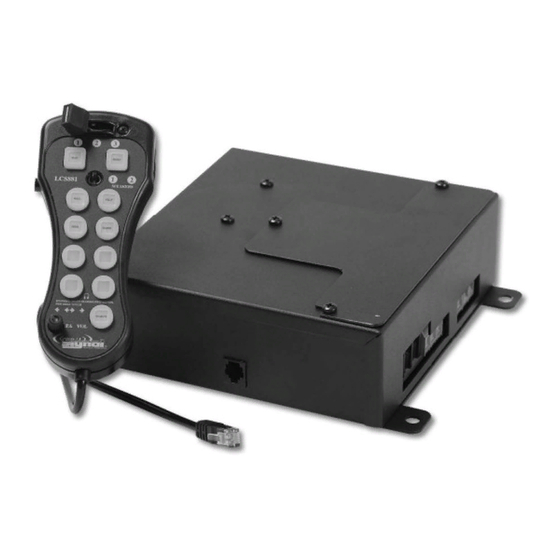
- Page 1 INSTALLATION AND INSTRUCTION MANUAL LCS880-008 & LCS881-8 SIREN AMPLIFIER & HAND-HELD LIGHT CONTROLLER PLITSTR309 REV. L 5/13/14...
- Page 2 Please Note: These instructions are provided as a general guideline only. Some vehicles may require special mounting, wiring, and/or weather-sealing. This is the sole responsibility of the installer. Star Headlight & Lantern Co., Inc. assumes no responsibility for the integrity of the installation for this or any of its products.
- Page 3 Due to continuous product improvements, we must reserve the right to change any specifications and information, contained in this manual at any time without notice. Star Headlight & Lantern Co., Inc. makes no warranty of any kind with regard to this manual, including, but not limited to, the implied warranties of merchantability and fitness for a particular purpose.
-
Page 4: Table Of Contents
Table of Contents INSTALLER INFORMATION i-ii GENERAL DESCRIPTION INSTALLATION NOTES INSTALLER SELECTABLE OPTIONS Siren Option DIP Switches Control Head Option Jumpers MOUNTING 9-10 Siren Amp & Relay Control Box Cradle Mounting Arrow Stick Control Box ELECTRICAL CONNECTIONS 11-17 Wire Size And Termination Siren Amplifier 11-14 Siren Wiring Diagram... -
Page 5: General Description
2A in-line fuse. CAUTION: These protection features will not guard against overloading the outputs. The LCS880 series is available in the following different versions: LCS880-008 Standard version with slide switch, full siren controls, and light controls. Includes a remote hand-held controller with microphone and a siren amplifier/switch relay box. -
Page 6: Installation Notes
Installation Notes Proper installation of the unit is essential for years of safe, reliable operation. Please read all instructions before installing the unit. Failure to follow these instructions can cause serious damage to the unit or vehicle and may void warranties. Qualifications - The installer must have a firm knowledge of basic electricity, vehicle electrical systems, and emergency equipment. -
Page 7: Siren Option Dip Switches
(Installer Selectable Options CONT’D) SIREN OPTION DIP SWITCHES Amplifier Cover Removal Loosen the three protruding Philips head screws located on the top of the amplifier unit. Slide the cover off. CAUTION: DO NOT OVER TIGHTEN SCREWS! Auxiliary Input Polarity Applying a positive voltage to the green wire normally activates the auxiliary function (Air Horn standard/MANUAL function optional). - Page 8 (Installer Selectable Options CONT’D) Park Kill Input Polarity The Park Kill (Cutout) Input turns off any siren tone output when activated, and remains off until a control is activated or changed. The wiring diagram on page 13 shows two connection examples. Connecting the white wire to positive (+12 VDC) normally activates the Park Kill input.
- Page 9 (Installer Selectable Options CONT’D) Phaser Disable The Phaser function can be completely disabled by turning on (up position) DIP switch #4 in the amplifier (labeled PD). This will also disable the MAN button while the siren is in Phaser mode (which normally would produce a Two-Tone sound). Pursuit Disable Slide switch position 3 normally activates: •...
-
Page 10: Control Head Option Jumpers
(Installer Selectable Options CONT’D) CONTROL HEAD OPTION JUMPERS Five jumpers located inside the hand held controller can be used to select various options. Review the chart below to determine if you want to change any of the default settings. Jumper Controlled Options Jumper Standard Setting Optional Setting... - Page 11 (Installer Selectable Options CONT’D) If you are NOT changing any of the options described on the previous page, skip this section. Control Head Cover Removal • Remove the three Philip head screws recessed in the back of the hand held controller. •...
- Page 12 (Installer Selectable Options CONT’D) Programmable Options (LCS881 ONLY) S4=S3+S2+S1 • WAIL Tone Auto-Activate By Slide Switch • • TD WARN Auto-Activate By Slide Switch The LCS881 has a number of additional programmable option that are NOT available in the LCS880. To program these options: •...
-
Page 13: Mounting
Mounting SAFETY PRECAUTIONS For the safety of the installer, vehicle operator, passengers, and the community please observe the following safety precautions. Failure to follow all safety precautions and instructions may result in property damage, injury or death. DO NOT mount in air bag deployment area. Devices should be mounted only in locations listed in SAE standard J1849. -
Page 14: Arrow Stick Control Box
(Mounting CONT’D) ARROW STICK CONTROL BOX MOUNTING (MODEL LCS881 only) • Review the Arrow Stick Settings and Connections (pages 18-22) section for details on any option jumper settings prior to installing this control box. • The TDC850 arrow stick control box is usually mounted near the siren amplifier and relay control box in a location such as the driver compartment firewall, under the seat, or in the trunk. -
Page 15: Electrical Connections
Electrical Connections WIRE SIZE AND TERMINATION • The wiring diagrams on pages 13 and 17 show the minimum wire size used for each connection, along with recommended lead color. • If the wire is longer than 10 ft., use the next larger wire size. •... - Page 16 (Electrical Connections: Siren Amplifier CONT’D) Siren electrical power connections to the amplifier are made using a removable connector located on the back of the amplifier case. The power supply to the siren unit must be capable of delivering peak currents up to 50 amps for adequate short circuit protection and reliable operation.
-
Page 17: Siren Wiring Diagram
(Electrical Connections: Siren Amplifier CONT’D) -13-... -
Page 18: Horn Ring Transfer Wiring Diagram
(Electrical Connections: Siren Amplifier CONT’D) Wiring Diagram for OPTIONAL Horn Ring Transfer (HRT) Use this wiring diagram if you are connecting the Orange wire to utilize the Horn Ring Transfer Feature. This feature de-activates the vehicle horn when the handset is activated with the recessed On/Off switch on the side. -
Page 19: Rfi Reduction And Rfi Choke Installation
4. Excess communication cable from the control head to the amp should be tightly bound back near the amplifier box. 5. One of the RFI chokes (STAR P/N: P30039-57) should be placed around the communications cable at the back of the siren amplifier box. -
Page 20: Input Power And Switch Output Connections
(Electrical Connections CONT’D) INPUT POWER AND SWITCH OUTPUT CONNECTIONS Top View (Cover Removed) Input Power Slide Switch Outputs Side View Push Button Outputs (REFER TO LIGHT WIRE DIAGRAM ON NEXT PAGE, AS WELL AS TO WIRE SIZE TABLE ON PAGE 11 FOR PROPER WIRE SIZES!) The electrical connections for input power, slide switch outputs, and the push button outputs are made to the control box (amplifier) using terminal blocks (top diagram above). -
Page 21: Light Wiring Diagram
(Electrical Connections: Light Relay Control Box CONT’D) -17-... -
Page 22: Arrow Stick Settings And Connections
Arrow Stick Settings and Connections (LCS881 only) The TDC850 controller that is shipped with the LCS881 has been designed so that it can operate three different styles of traffic directors: • Independently Switched Heads: Each Head is independently controlled by a ground-side switched wire. - Page 23 (Arrow Stick Settings and Connections CONT’D) Jumper Options for Independently Controlled Heads If you are installing a 3- or 4–wire logic TDC850 Controller controlled arrow stick, skip this section. The options described below only apply to arrow sticks with independently controlled heads. Extra Jumper Locations Jumper Defaulted In Center Header...
-
Page 24: Arrow Stick Wiring
(Arrow Stick Settings and Connections CONT’D) ARROW STICK WIRING The arrow stick control box comes with a removable green terminal block connector (Power Connector). Remove the terminal block from control box and loosen all applicable terminal screws. This will open the wire entries. Make the power wire connections as described in the section that corresponds to the type of arrow stick you are connecting. - Page 25 (Arrow Stick Wiring CONT’D) Arrowsticks With 3-Wire Logic Control VERIFY MODE JUMPER SETTING ON PAGE 18 !! This diagram shows how to connect the wires from an arrow stick that is logic controlled by 3 positive switched wires (Right, Left, and WARN) AND uses a separate POWER wire.
-
Page 26: Label Insertion
(Arrow Stick Settings and Connections CONT’D) CAUTION: NOT REPLACEABLE WITH A STANDARD TELEPHONE CABLE TDC850 ARROWSTICK POWER SUPPLY 6-wire Cable Splitter SIREN AMPLIFIER HAND-HELD CONTROLLER A communications cable splitter is provided with these units. Using the communication cables, plug both the Arrow stick box and the control head into the cable splitter, and then plug the splitter into the amplifier box. -
Page 27: Operation
Operation GENERAL This unit is designed for easy operation under the stress associated with high-speed pursuit. Many light and siren functions are accessible with one simple motion of the slide switch. POWER The unit is turned On and Off by a recessed switch on the side of the hand held controller. -
Page 28: Siren Mode Buttons
(Operation CONT’D) SIREN MODE BUTTONS: The six push buttons towards the top of the control head allow full siren operation. When not activated, these buttons are backlit in green for nighttime viewing. When activated, an audible beep is heard, and the backlighting turns red. MAN (Manual) This button is used to temporarily change the siren output. -
Page 29: Microphone
(Operation CONT’D) MICROPHONE and MICROPHONE BUTTON The integrated noise-canceling microphone is used for public address operation and overrides any siren tone when the push-to-talk microphone button is pressed. PA VOLUME The PA volume control is provided for public address volume. This is in the bottom left corner of the control head. -
Page 30: Radio Repeat Volume
(Operation CONT’D) RADIO REPEAT VOLUME The radio repeat volume is located within the rear access cover of the amplifier. This should be set during installation when the vehicle is parked. Under normal circumstances, you should not need to adjust it again. First set the volume level of the vehicle’s two-way radio to its normal operating volume. -
Page 31: Service
Service TROUBLESHOOTING Symptom Possible Cause Check No power No power supplied to +12 terminal block Does back-lighting come on? inputs in amplifier. Connector loose Do you hear a “pop” when turned on? Amplifier 20A fuse or 5A fuse blown Is power hooked up backwards? Positive ground vehicle? Is an external fuse or circuit breaker used? Loose connection at power source... -
Page 32: Parts
(Service CONT’D) PARTS Part Description LCS850-AMP8 Amplifier Only LCS880-CH Hand-Held Controller for LCS880 LCS881-C Hand-Held Controller for LCS881 TDC850 Arrowstick Power Supply P30255-43A Amp Wiring Harness 30008-22 25’ Communication Cable Between Control Head Cable and Amp* 30041-52 Female/Female RJ11 Connector for Communication Cables 30008-30 7’... -
Page 33: Warranty
(Service CONT’D) ONE YEAR LIMITED WARRANTY The manufacturer warrants each new product against factory defects in material and workmanship for one year after the date of purchase. The owner will be responsible for returning to the Service Center any defective item(s) with the transportation costs prepaid. manufacturer will, without charge, repair or replace at its option, products, or part(s), which its inspection determines to be defective. -
Page 34: Returned Materials Authorization (Rma) Form
(Service CONT’D) If a problem with this product develops within the warranty period, please contact our Customer Service Department at (585) 226-9025. When contacting us about a product you have purchased, please have the product’s serial number readily available. If the product needs to be returned, you will be issued an RMA number (Returned Materials Authorization Number). -
Page 35: Flanged Control Head Template
-31-... - Page 36 -32-...
Need help?
Do you have a question about the LCS880-008 and is the answer not in the manual?
Questions and answers