
Related Manuals for TES TES-2620


Summary of Contents for TES TES-2620
-
Page 1: Instruction Manual
AUTO-RANGING TRUE RMS MULTIMETER TES-2620 INSTRUCTION MANUAL TES ELECTRICAL ELECTRONIC CORP. -
Page 2: Table Of Contents
CONTENTS TITLE PAGE 1. SAFETY INFORMATION ..........1 2. FEATURES ..............2 3. SPECIFICATIONS ............2 3-1 General Specifications ..........2 3-2 Electrical Specifications .......... 5 4. PARTS & CONTROLS ........... 9 4-1 Name Of Parts And Positions ......... 9 4-2 Precautions And Preparations For Measurement............ -
Page 3: Safety Information
1. SAFETY INFORMATION Read the following safety information carefully before attempting to operate or service the meter. To avoid damages to the instrument do not apply the signals which exceed the maximum limits shown in the technical specifications tables. Never measure current while the test leads are inserted into the input jacks. Do not use the meter or test leads if they look damaged. -
Page 4: Features
2. FEATURES 3-3/4 Digital LCD with Bar-graph True RMS on ACV and ACA measurement Water- Proof ABS housing Auto- Ranging on Volt, Ohm , Current, Frequency, and Capacitance measurement Auto-power - off Also provides MAX / MIN recording; MEM and READ; REL and data HOLD mode Ohms, Diode, Audible continuity, Capacitance range with input Overload protection to 600Vrms... - Page 5 Unit and Sign Display : Decimal point ■ Alternating current or voltage Direct current or voltage Volt Millivolt ( 1 × 10 volt ) Ampere ( amp ). Current Milliampere ( 1 × 10 amp ) Ω Ohm. Resistance K Ω Kilohm ( 1 ×...
- Page 6 Diode Continuity Beeper Low Battery Negative polarity Auto Autorange Manu Manual Range △ REL Relative Reading Memory Reading Date Hold...
- Page 7 Minimum Reading Maximum Reading Range Selection : All ranges are measured by single Range Switch operation. Over Range Indication : LCD will show a “4” flashing in the highest position accompanied with a continuous beeper. Low Battery Indication : The is displayed when the battery voltage drops below the operating voltage.
-
Page 8: Electrical Specifications
3-2 Electrical Specifications Accuracies are ± (...% of reading + ...digits) at 23 ℃± 5 ℃ ,below 80% RH. DC Voltage : ( Autoranging & Manual range ) Input Overload Range Resolution Accuracy Impedance Protection 400mV 100uV > 100M Ω ≒... - Page 9 DC Current : ( manual range ) Burden Range Resolution Accuracy Input Impedance Voltage 0.45V 1%+1 0.5A / 250V fuse 40mA 10uA 400mA 100uA 0.65V 10mA 1.5%+2 1.3V 20A / 600V high energy fuse AC Current : (manual range ) True RMS Frequenc Burden Range Resolution...
- Page 10 Audible Continuity: Open Circuit Continuity Overload Range Resolution Voltage Beeper Protection ≤ 0.5V ≤ Approx. 40 Ω 600Vrms 0.1 Ω Diode Test: ( Short Circuit Open Circuit Overload Range Resolution Accuracy Current Voltage Protection 0.8mA typical 1%+ 2 600Vrms Capacitance (Cx): (Autoranging & Manual range ) Range Resolution Accuracy...
- Page 11 Frequency (Hz): ( Autoranging ) Range Resolution Accuracy Sensitivity 100HZ 0.01HZ 1KHZ 0.1HZ 100mV / 1V / 10V 0.1%+ 2 10KHZ (By Range Button Selector ) 100KHZ 10HZ 500KHZ 100HZ Overhead Function Input Resolution Accuracy Protection 400mV ± 0.5% of rdg ± 2LSD 1 COUNT/0.1mV 600Vrms Full Scale...
-
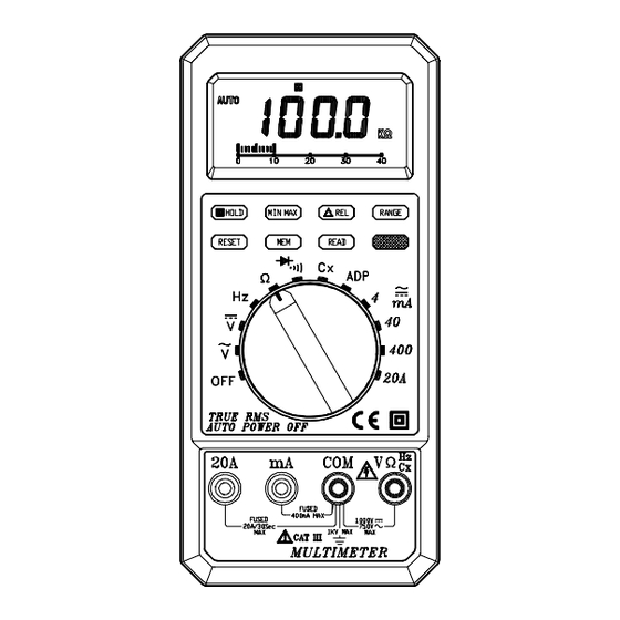
Page 12: Parts & Controls
4. PARTS & CONTROLS 4-1 NAME OF PARTS AND POSITIONS:... - Page 13 1. 20A Measuring Connector To connect positive lead ( red test lead ) for current measurement below 20A. 2. mA Measuring Connector To connect positive lead ( red test lead ) for current measurement 400mA. 3. COM Measuring Connector To connect negative lead ( black test lead ) for voltage, current, resistance, frequency, Diode, continuity, capacitor, ADP measurement.
- Page 14 7. AC/DC Current Select and Buzzer / Diode function Select and Cancel Auto- Power-OFF function Button: To select function DC or AC current. To select function buzzer or Diode. Cancel Auto-Power-OFF function : Press and Hold down the red button to turn the rotary switch from OFF to any function position about two seconds.
- Page 15 15. Auto-range Mode Meter is in the autorange mode and will automatically select the range with the best resolution. Meter powers-on in autorange mode. 16. Negative Polarity Automatically indicating negative inputs. 17. Manual-range Mode indicator. 18. Low Battery As battery power is not sufficient. LCD will display 19.
-
Page 16: Precautions And Preparations For Measurement
4-2 PRECAUTIONS AND PREPARATIONS FOR MEASUREMENT (1) DO NOT attempt to take any voltage or current measurement that maybe exceed the maximum range of this instrument. (2) Be sure that battery is correctly placed in the case and connected to the battery snap. (3) Make certain the range selected is greater than circuit current or voltage prior to attempting a measurement. -
Page 17: Ac Voltage Measurements
(1) Connect red test lead to “ V Ω “terminal and black test lead to “ COM” terminal. (2) Set Range Switch to range. (3) Connect Test Prods of test leads IN PARALLEL to the circuit being measured. (4) Read the Voltage value on LCD. 4-4 AC Voltage Measurement ( True RMS Measurement ) WARNING Maximum Input Voltage of AC VOLT Range is 750VAC. -
Page 18: Ac Current Measurements
(2) Set Range Switch to desired A range. and press AC / DC Switch to DC function. (3) Cut the power to the circuit being tested and Connect the instrument IN SERIES with the circuit , with the black test lead on the negative side and the red lead on the positive side... -
Page 19: Continuity Measurement & Diodes Test
4-8 Continuity Measurement & Diode test Press “ Red “ button to select " " or " " function. WARNING Before taking any in- circuit measurement, remove power from the circuit being tested and discharge all capacitors in the circuit. CONTINUITY MEASUREMENT (1) Connect red test lead to the "... -
Page 20: Resistance Measurement
4-9 Resistance Measurement WARNING Before taking any in-circuit resistance measurement, remove power from the circuit being tested and discharge all Capacitors. (1) Connect red test lead to “ V Ω “terminal and black test lead to “ COM” terminal. (2) Set Range Switch to Ω range. (3) Connect Test Lead to the Circuit being measured and read the resistance Value on LCD. - Page 21 If the input differs significantly from a sine wave, the reading is incorrect as a different conversion factor would relate the average value of the signal to its rms value (see table as below). Correct measurements of non- sinusoidal wave forms can be made directly with the true- RMS models.
-
Page 22: Adaptive ( Adp ) Measurement
4-12 Adaptive ( ADP ) Measurement (1) Connect the BLACK test lead to the COM terminal and the RED test lead to the “ V- Ω -ADP “ terminal. (2) Set the rotary switch to “ ADP “ position. (3) Connect the test leads across the source or load under measurement. - Page 23 TES ELECTRICAL ELECTRONIC CORP. Add: 7F, No. 31, Lane 513, Rui Guang Road, Neihu Dist. Taipei. Taiwan, R. O. C. Tel : (02) 2799-3660 Fax : 886-2-2799-5099 E-Mail : tes@ms9.hinet.net http://www.tes.com.tw Mar-2000-2...
Need help?
Do you have a question about the TES-2620 and is the answer not in the manual?
Questions and answers