Advertisement
Quick Links
®
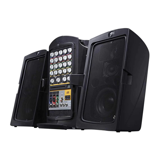
PASSPORT
PD-150 PLUS
(This is the model name for warranty claims)
p/n 069-3005-000
SERVICE MANUAL
ATTENTION:
WARRANTY SERVICE PROCEDURES
Warranty field service of the Passport PD-150 Plus will be limited to replacement of
defective PCB Assemblies and all other parts not marked as "REF" in the Parts List. Non-
Warranty repairs can of course be to the component level at the Service Center's
discretion. For non-warranty component level repairs all parts listed as "REF" in the Parts
List must be sourced from suppliers other than FMIC.
Fender Musical Instruments Corporation, 8860 East Chaparral Road Suite 100 Scottsdale, AZ 85250
Issued: October, 2006
Advertisement

Related Manuals for Fender PASSPORT PD-150 PLUS


Summary of Contents for Fender PASSPORT PD-150 PLUS
- Page 1 ATTENTION: WARRANTY SERVICE PROCEDURES Warranty field service of the Passport PD-150 Plus will be limited to replacement of defective PCB Assemblies and all other parts not marked as “REF” in the Parts List. Non- Warranty repairs can of course be to the component level at the Service Center’s discretion.
- Page 2 Fender® Musical Instruments Corporation. It is Corporation. not to be sold or assigned to another party and is disclosed solely for use by Fender Authorized • Parts marked with two asterisks ( Service Centers for purposes of product service ) indicate the and maintenance.
-
Page 3: Specifications
® PASSPORT PD-150 PLUS (This is the model name for warranty claims) SPECIFICATIONS Model Name: PASSPORT PD-150 PLUS Release Number: PR688 Part Number: (120V, 60Hz) US: 069-3005-000 (120V, 60 Hz) DS: 069-3005-900 (240V, 50 Hz) AUS: 069-3005-930 (230V, 50 Hz) UK:... -
Page 4: Service Notes
® PASSPORT PD-150 PLUS (This is the model name for warranty claims) SERVICE NOTES The following describes the procedure to dismantle B3. Unscrew nine M3 machine screws from the the PD-150+ Cabinets. mixer PCB assembly. B4. Detach all connectors. STEP A: PD-150+ CABINET B5. - Page 5 ® PASSPORT PD-150 PLUS (This is the model name for warranty claims) H4. Detach all wiring from the SMPS cabinet. STEP G: PD150+ LCD KEY PCB H5. Unscrew four M2 machine screws from the CD SERVO PCB assembly G1. Unscrew six screws from the LCD KEY PCB. H6.
-
Page 6: Circuit Description
T1 which independently Information is focused for its effective use while supplies +42.5VDC power to the class-D amplifier maintaining the security of Fender® proprietary PCB assembly. The bridge rectifier BD2 rectifies the information wherever possible. AC input separately from LF2 and feeds the DC to U2 (TOP249Y). - Page 7 ® PASSPORT PD-150 PLUS (This is the model name for warranty claims) These signals from each channel are mixed at the inputs of U209A and U209B. From here they are The LCD Key PCB Module controlled by U210A and U210B for Master Volume Left and Right, and then by U211A and U211B for The LCD Key PCB module consists of U701 System EQ Left and Right.
-
Page 8: Parts List
+ * Access to this part or assembly is controlled. Please contact the FMIC Customer Service Department. ** Safety Requirement part. Replacement must match Safety Agency…–Value, if specified –Type, if specified –Approval Mark(s) if on part. shaded + ** Both a unique Fender® part and a Safety Requirement part as defined above. - Page 9 + * Access to this part or assembly is controlled. Please contact the FMIC Customer Service Department. ** Safety Requirement part. Replacement must match Safety Agency…–Value, if specified –Type, if specified –Approval Mark(s) if on part. shaded + ** Both a unique Fender® part and a Safety Requirement part as defined above.
- Page 10 + * Access to this part or assembly is controlled. Please contact the FMIC Customer Service Department. ** Safety Requirement part. Replacement must match Safety Agency…–Value, if specified –Type, if specified –Approval Mark(s) if on part. shaded + ** Both a unique Fender® part and a Safety Requirement part as defined above.
- Page 11 + * Access to this part or assembly is controlled. Please contact the FMIC Customer Service Department. ** Safety Requirement part. Replacement must match Safety Agency…–Value, if specified –Type, if specified –Approval Mark(s) if on part. shaded + ** Both a unique Fender® part and a Safety Requirement part as defined above.
- Page 12 + * Access to this part or assembly is controlled. Please contact the FMIC Customer Service Department. ** Safety Requirement part. Replacement must match Safety Agency…–Value, if specified –Type, if specified –Approval Mark(s) if on part. shaded + ** Both a unique Fender® part and a Safety Requirement part as defined above.
- Page 13 + * Access to this part or assembly is controlled. Please contact the FMIC Customer Service Department. ** Safety Requirement part. Replacement must match Safety Agency…–Value, if specified –Type, if specified –Approval Mark(s) if on part. shaded + ** Both a unique Fender® part and a Safety Requirement part as defined above.
- Page 14 + * Access to this part or assembly is controlled. Please contact the FMIC Customer Service Department. ** Safety Requirement part. Replacement must match Safety Agency…–Value, if specified –Type, if specified –Approval Mark(s) if on part. shaded + ** Both a unique Fender® part and a Safety Requirement part as defined above.
- Page 15 + * Access to this part or assembly is controlled. Please contact the FMIC Customer Service Department. ** Safety Requirement part. Replacement must match Safety Agency…–Value, if specified –Type, if specified –Approval Mark(s) if on part. shaded + ** Both a unique Fender® part and a Safety Requirement part as defined above.
- Page 16 + * Access to this part or assembly is controlled. Please contact the FMIC Customer Service Department. ** Safety Requirement part. Replacement must match Safety Agency…–Value, if specified –Type, if specified –Approval Mark(s) if on part. shaded + ** Both a unique Fender® part and a Safety Requirement part as defined above.
- Page 17 ® PASSPORT PD-150 PLUS (This is the model name for warranty claims) Service Diagram List Service Diagram (Schematic) ....CD SERVO Service Diagram (Schematic) ....LCD DISPLAY Service Diagram (PCB Assembly) ....CD SERVO & LCD DISPLAY PCB Service Diagram (Schematic) ....D-AMP Service Diagram (PCB Assembly) ....D-AMP PCB Service Diagram (Schematic) ....INPUT Service Diagram (PCB Assembly) ....INPUT PCB Service Diagram (Schematic) ....MIXER...
- Page 18 MGND PASSPORT CD SERVO Schematic...
- Page 19 C704 0.1UF C703 0.1UF PASSPORT LCD DISPLAY Schematic Diagram...
- Page 20 CD Servo PCB Copper Side CD Servo PCB Component Side LCD Display PCB Copper Side LCD Display PCB Component Side PASSPORT CD SERVO & LCD DISPLAY PCB...
- Page 21 PASSPORT D-AMP Schematic Diagram...
- Page 22 D-AMP PCB Copper Side D-AMP PCB Component Side PASSPORT D-AMP PCB...
- Page 23 PASSPORT INPUT Schematic Diagram...
-
Page 24: Input Pcb
Input PCB Component Side Input PCB Copper Side PASSPORT INPUT PCB... - Page 25 JUMPER JUMPER PASSPORT MIXER Schematic Diagram...
- Page 26 MIxer PCB Component Side PASSPORT MIXER PCB...
- Page 27 Mixer PCB Copper Side PASSPORT MIXER PCB...
- Page 28 PASSPORT DSP REVERB Schematic Diagram...
- Page 29 DSP Reverb PCB Component Side DSP Reverb PCB Copper Side OUTPUT PCB Component Side OUTPUT PCB Copper Side PASSPORT DSP REVERB PCB...
- Page 30 PASSPORT SMPS Schematic Diagram...
- Page 31 SMPS PCB Component Side PASSPORT SMPS PCB...
- Page 32 SMPS PCB Copper Side PASSPORT SMPS PCB...
- Page 33 DC380V DC 322V PASSPORT Test Point Information...
- Page 34 PASSPORT Test Point Information...
- Page 35 TP10 TP11 PASSPORT Test Point Information...
- Page 36 TP12 TP13 DC 5V TP14 DC 21V TP15 DC 21V TP16 DC 21V TP17 DC 21V TP18 PASSPORT Test Point Information...
- Page 37 TP19 DC 6V TP20 DC 3.3V TP21 TP22 PASSPORT Test Point Information...
- Page 38 TP23 TP24 PASSPORT Test Point Information...
- Page 39 PASSPORT Wiring Diagram...
-
Page 40: Wiring Diagram
The following shows the legend of the mating connections SVC-PD15011+CD SVC-PD15011+LCD 1 MCU RESET 1 MCU RESET 2 3.3V 2 3.3V 3 3.3V 3 3.3V 4 GND 4 GND 5 GND 5 GND 6 LOAD+ 6 LOAD+ 7 8V 7 8V 8 LOAD- 8 LOAD- 9 LOADER SW3... - Page 41 6 GND 6 GND SVC-PD15011+DREV SVC-PD15011+MIXER 1 -15V 1 -15V 2 GND 2 GND 3 15V 3 15V CN401 CN208 4 INPUT 4 INPUT 5 GND 5 GND 6 OUTPUT 6 OUTPUT SVC-PD15011+INPUT SVC-PD15011+MIXER 1 L STEREO OUT 1 L STEREO OUT 2 GND 2 GND 3 R STEREO OUT...
- Page 42 Front Panel Assy Exploded View (2) PASSPORT Front Panel Assy Exploded View (1) Front Panel Assy Exploded View...
- Page 43 Front Panel Assy Exploded View (3) NO. DESCRIPTION PART NUMBER NO. DESCRIPTION PART NUMBER PCB ASSY DSP REVERB COVER-FRONT CD 0074508000 SCREW B-TITE BIND HEAD M3X8 REF LENS-LCD 25.7X14.7X4.2 WASHER METAL M3X0.3X4 WZ FELT METAL WASHER 2113-1340+0 COVER FELT M9 NUT 2113-1340+0 PC SHEET OVERLAY FIBER WASHER M3X0.8X8MM KNOB-SMALL...
- Page 44 Power Supply Assy Exploded View (1) PASSPORT Power Supply Assy Exploded View...
- Page 45 Power Supply Assy Exploded View (2) NO. DESCRIPTION PART NUMBER NO. DESCRIPTION PART NUMBER QTY FAN PANEL DC FAN SCREW 3X10 COVER-TOP POWER D-AMP PCB ASSY HALD BUSHING 0074492000 SCREW 3X14 POWER INLET SOCKET SPRING WASHER M3 SCREW 3X10 WASHER M3 MODULE SMPS PCB 0074497000 MTG.
- Page 46 Speaker Assy Exploded View DESCRIPTION PART NUMBER PD150 8 OHM WOOFER PD150 TWEETER BACK PD150 BAFFLE PD150 STAND PLUG 4132-4871-0 GRILLE 7251-7-0 GASKET SPEAKER SPRUE CAP (BLK) PD15011 SPEAKER BADGE (BLACK) SCREW B-TITE BH M4X14MM BZ CROSS SCREW TAP-C2 BH M4X10MM BZ CROSS SCREW B-TITE FLAT-CS M3X10MM BZ CROSS 2666-12 M12 WASHER NI 2666-11 M12 NUT NI...
- Page 47 Latch Assy Exploded View DESCRIPTION PART NUMBER 1464-3500-0 LATCH 4132-4681-0 LATCH BKT 4132-4691-0 C PIN 2751-5-0 SPRING-LATCH 1464-3600-0 LATCH LICKER PASSPORT Latch Assy Exploded View...
- Page 48 CROSS 1464-3800-0 LOCKER DOOR 4132-4871-0 SIDE PLATE-A F3X10MM SELF TAPPING METAL WASHER M3X0.5X8MM BZ 1464-4200-0 HINGE FENDER BADGE PD150 2751-6-0 COMPRESSION SPRING SPRUE CAP (BLACK) FOOT STAND PD150 4X16MM PA 1464-3400-0 SUPPORT RIB SCREW S-TITE 4X16MM PH BLK ZINC REF 4132-4901-0 HANDLE BKT SPRING WASHER M4X0.8X6.5MM BZ REF...
- Page 49 Main Unit Assy Exploded View (1) DESCRIPTION PART NO. SPEAKER ASSEMBLY 0074498000 TOWER HOUSING ASSEMBLY GIG BAG MICROPHONE MIC CABLE MIC CLIP 2751-12-0 DUST FILTER PASSPORT Main Unit Assy Exploded View (2) Main Unit Assy Exploded View...
- Page 50 Packing Assy Exploded View (2) NO. DESCRIPTION PART NO. NO. DESCRIPTION PART NO. GIFT BOX PD150 2751-P5-0 P.E. FOAM 2751-P12-0 POLYBAG SPK CABLE MONO 90 ANGLE PLUG L=30FT 2751-P1-0 INNER PAD SJT #18/3C 2M BLK POWER 2751-P2-0 INNER PAD CORD 2751-P3-0 INNER PAD OWNER’S MANUAL PD150 2751-P4-0 P.E.
Need help?
Do you have a question about the PASSPORT PD-150 PLUS and is the answer not in the manual?
Questions and answers