Table of Contents
Advertisement
10.2.1.4 Edition 01.12 GB
Operating and installation instructions
Lago FB OT digital remote control
Translation from the German
© 2012 Elster GmbH
Safety
Safety
Please read and keep in a safe place
Please read through these instructions carefully before
installing or operating. Following the installation, pass the instruc-
tions on to the operator.
These instructions can also be found at www.docuthek.com.
Explanation of symbols
• , 1 , 2 , ... = Action
▷
= Instruction
Liability
We will not be held liable for damages resulting from non-observance
of the instructions and non-compliant use.
Safety instructions
Information that is relevant for safety is indicated in the instructions
as follows:
DANGER
Indicates potentially fatal situations.
WARNING
Indicates possible danger to life and limb.
CAUTION
Indicates possible material damage.
All work and settings in the "Expert" chapters may only be carried
out by a qualified technician. Electrical interventions may only be
carried out by a qualified electrician. The heating system must be
disconnected from the power supply before any electrical work is
carried out on the unit.
Conversion
All technical changes are prohibited.
Transport
On receipt of the product, check that the delivery is complete. Report
any transport damage immediately.
Storage
Store the product in a dry place. Ambient temperature: see Techni-
cal data.
Advertisement
Table of Contents

Related Manuals for Krom Schroder Lago FB OT

Summary of Contents for Krom Schroder Lago FB OT
-
Page 1: Lago Fb Ot Digital Remote Control
Liability Operating and installation instructions We will not be held liable for damages resulting from non-observance Lago FB OT digital remote control of the instructions and non-compliant use. Safety instructions Information that is relevant for safety is indicated in the instructions... -
Page 2: Table Of Contents
Table of contents Lago FB OT digital remote control..... 1 User – Set parameters ......1... - Page 3 Table of contents P10 Integral control section ....... . .20 P11 Transparent Slave Parameter 01 .
-
Page 4: Verify Type Of Application
R es et hot water temperature and monitoring of boiler data in the living area. The LAGO FB OT uses the weather or room-based control function to transmit the desired boiler value to the boiler controller via the Pr og /1 ... -
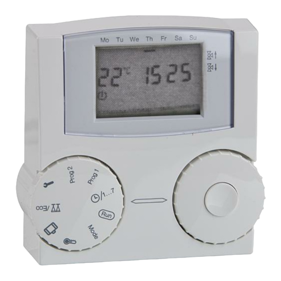
Page 5: Display
Verify type of application Display Operating modes: Operational readiness/OFF (Heating and hot water Mo Tu We Th Sa Su preparation OFF, frost protection operation only) 1 Automatic mode 1 (Heating according to heating program 1, hot water according to parameter 04) 2 Automatic mode 2 (Heating according to heating program 2, hot water according to parameter 04) Reset... -
Page 6: User - Settings
User – Settings Set the desired temperature User – Settings The desired temperatures set the room temperatures for the heating phase (desired daytime temperature) and the setback phase (desired night-time Set time and day of the week temperature). The desired temperature for the hot water can be adjusted. 1 Turn selector switch to 1...7. -
Page 7: Display Actual Temperatures
User – Settings Set operating mode 5 Turn the rotary knob clockwise. ▷ The desired temperature selection is displayed, flashes. The operating mode determines how the heating controller works. 6 Press the OK button. Whether the heating system is to be controlled automatically or man- ▷... -
Page 8: Night Mode (Reduced Night Mode)
User – Settings Set heating program 1 Night mode (reduced night mode) Heating is reduced to the setback temperature on a permanent Heating program 1 is assigned to automatic mode 1. It is used basis. Hot water according to parameter 04, see page 15 (P04 to define the heating times for the working week (Mon–Fri) and the Hot water according to program). -
Page 9: Set Heating Program 2
User – Settings ▷ The new end time is displayed. Example: Display of the heating times for heating program 1 9 Turn the rotary knob clockwise. Heating takes place from Monday to Friday between 6:00 and 8:00 10 Press the OK button. in the morning, from 11:30 to 13:00 at lunchtime and from 18:00 to ▷... -
Page 10: Holiday Setting/Holiday Duration
User – Settings Holiday setting/holiday duration 2 Press the OK button. The start time of the first heating time flashes. In holiday mode, you can make a distinction between a “Present” Use the rotary knob to select the start time. holiday where you remain at home and an “Absent”... -
Page 11: Heating Time Setting/Change Duration
User – Settings ▷ The days are automatically counted down every 24 hours. 5 Finally, turn the selector switch back to ▷ The last operating mode selected is displayed. Absent holiday ▷ During the holiday, the room is heated to 15 °C. Heating time setting/Change duration The setting for this function depends on the current operating mode Mo Tu We Th... -
Page 12: Load Factory Settings (Reset)
User – Settings Load factory settings (Reset) Example interruption of heating time. If you leave the house for a few hours, you can reduce the heating ▷ All personal settings, switching times and the CODE-NO are during an active heating program to save energy. Once the set time reset to the factory defaults. -
Page 13: User - Set Parameters
User – Set parameters User – Set parameters You can change further parameters to adapt the heating system to your requirements. 1 Turn selector switch to (parameter setting). ▷ The display shows 2 Turn the rotary knob clockwise until the parameter you want to change appears in the left-hand side of the display: 01 to 04 (heat slope to hot water, based on program). -
Page 14: Explanation Of The Parameters
User – Set parameters Explanation of the parameters P01 Heat slope Selecting the correct heat slope saves energy because the heat sources only heat to the point required by the respective outside temperature. The heat slope specifies the number of °C by which the flow tem- perature changes when the outside temperature rises or drops. -
Page 15: P03 Room Sensor Correction
User – Questions Example: P02 = 5 User – Questions With this setting the desired temperature of the heat source is in- creased by 5 °C when the room temperature drops below the desired How do I switch to summer/winter time? room temperature by 1 °C. -
Page 16: My Heating Does Not Get Warm Enough. What Can I Do
User – Questions My heating does not get warm enough. What Is it possible to let the heating system run longer can I do? in the evening for special occasions such as a party? You have two options. First increase the desired room temperature Day, see page 6 For this purpose, set the operating mode to /Eco, see page 11 (Set the desired temperature). -
Page 17: Expert - Installation
Expert - Installation Remove remote control holder and use the drill holes to affix it to an Expert - Installation internal wall in the living area. CAUTION Fr Sa Tu We The minimum distance from surrounding heat sources is to be cho- Fr Sa Tu We Pro g1... -
Page 18: Expert - Electrical Connections
Expert – Set parameters Expert - Electrical connections Expert – Set parameters ▷ Parameters P01 to P04 for users, see page 13 (User – Set WARNING parameters) Possible life-endangering electrical shock! Switch the power off to electrical cables before working on power-carrying parts! WARNING Incorrect settings can cause malfunctions and damage the heating CAUTION... -
Page 19: List Of Parameters P05 To P13
Expert – Set parameters ▷ Your remote control will only display those parameters for which there are sensors connected. List of parameters P05 to P1 P. no.: Parameter Setting range Factory setting Own values Code no. input 0000–9999 0000 Code no. change 0000–9999 ---- Max. -
Page 20: P09 Outside Temperature Frost Protection
Expert – Checklist for commissioning P09 Outside temperature frost protection Expert – Checklist for commissioning P09 = ----: Frost protection is deactivated. ❑ Remote control properly wired? See page 18 (Electrical socket P09 = -15.0 to +5.0 °C: When the outside temperature drops be- connection). -
Page 21: Accessories
Troubleshooting Accessories Troubleshooting ? Fault Outside sensor AF ! Cause • Remedy When a fault occurs, the error number is indicated in the display (Example: E 81). You can find the error numbers in the heat source instructions. Order no. AF, 5 kΩ: 99 679 030 ? The display shows an error no. -
Page 22: Technical Data
Technical data ? When displaying the actual values on the remote control, you Technical data realise that the indicated value does not match the real one. For Voltage supply via BUS 15–18 V DC example, the actual hot water temperature is 20 °C, but the Bus communication: OpenTherm display shows 65 °C (or vice versa). -
Page 23: Glossary
Declaration of conformity Glossary Declaration of conformity Flow temperature The flow temperature is the temperature to which the heat source heats the water that transfers the heat to the consumer (e.g. radiator). We the manufacturer declare the product Lago FB is in conformity with the fundamental requirements of the following directives and Desired and actual temperature standards. -
Page 24: Heating Circuit Allocation
Contact Heating circuit allocation For the installation expert Please enter which rooms the heating circuits are assigned to here. Direct heating circuit Mixed heating circuit Contact Contact If you have any technical questions, please contact your local branch Elster GmbH office/agent.
Need help?
Do you have a question about the Lago FB OT and is the answer not in the manual?
Questions and answers