Table of Contents
Advertisement
Quick Links
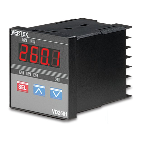
The Vertex VD series Temperature Controllers are a "Low Cost" Digital alternative to analog
controllers
, designed for use in simple applications where three term (PID) control is not required. It
comes from the factory with default settings making it an "on/off" controller but can be user configured to have
proportional action "proportional". It has a single digital display allowing access to all the parameters including
the "Process Variable" and "Set Point". It is fully configurable on input including PT100 (RTD).
There are three simple steps required to get you up and running:
1.
Installation 2. Wiring 3. Commissioning
Installation
Select the panel cut-out sizes from the table depending on the Model VD controller you have chosen and install
the controller accordingly in your panel.
■PANEL CUTOUT:
A
Model
A
VD-2600
48
VD-2601
72
VD-2603
96
VD-2604
96
Wiring
■WIRING DIAGRAM:
B
B
C
D
48
6
100
72
9
80
48
9
80
96
10
80
VERTEX VD 26 SERIES
USER MANUAL
E
a
45
45
+0.5
67
68
+0.5
45
92
+0.5
91
92
+0.5
b
c
45
60
48
+0.5
68
90
72
+0.5
45
48
120
+0.5
92
120
96
+0.5
d
1
Advertisement
Table of Contents

Related Manuals for Vertex VD 26 Series

Summary of Contents for Vertex VD 26 Series
- Page 1 VERTEX VD 26 SERIES USER MANUAL The Vertex VD series Temperature Controllers are a “Low Cost” Digital alternative to analog controllers , designed for use in simple applications where three term (PID) control is not required. It comes from the factory with default settings making it an “on/off” controller but can be user configured to have proportional action “proportional”.
- Page 2 Wiring Precautions: Before wiring please check the model you are using and establish the correct terminals you should use, by using this information and double checking it against the label on the label on the controller. Mains Power: 1.1 You can use any mains voltage between 90 and 264 Volts AC (50 or 60 Hz) or DC 1.2 You can also order the controllers with a “Low Voltage DC”...
- Page 3 7.2 If you are replacing an old controller of a different make, carefully identify each wire on the old controller and then substitute them in the correct position on the new VERTEX model. 7.3 Extreme care should be taken if attempting to do this as experience shows that most times when it goes wrong it was a simple swapping of a wire or two that causes the problem.
- Page 4 control signal input of 3 ~32 Vdc. 8.2 It will not work with SSR’s that have a control signal of 90~250 Vac. 8.3 If you have a SSR that works with 90~250 Vac you will need a relay output controller that will simply switch the higher voltage signal feeding the Solid State Relay.
- Page 5 SP-HYST SP+HYST ▲ ■ FRONT PANEL DESCRIPTION : (1)PV - Process Value (2)SV - Setting Value (3)C1 - Control LED (4)A1 - Alarm 1 LED (5)A2 - Alarm 2 LED (6)A3 - Alarm 3 LED SET KEY. Press once to access the next programmable parameter. press for 5 seconds to move from one programming level to next.
- Page 6 ■ PROGRAMMING LEVEL PARAMETERS lst. Prog. Level 2nd. Prog. Level 3rd. Prog. Level Press 5 seconds Press 5 seconds /Press 5 seconds...
- Page 7 These parameters will only be available when ≠ 0.0. When = 0.0. will be displayed instead. parameters will only be available when = t.on or t.Off. and will be skipped parameters will be available only when = LinE. and will be FIRST PROGRAMMING LEVEL PARAMETERS CODE DESCRIPTION...
- Page 8 Parameter lock. This security feature locks out selected levels or single parameters prohibiting tampering and inadvertent programming changes. 0000 All parameters are locked. 0001 Only SP is adjustable. 0010 USER (level) and A1(parameter) are adjustable. 0011 USER、PID(level) and A1、A2(parameter) are adjustable. 0100 USER、PID、OPTI(level) and A1、A2(parameter) are adjustable.
- Page 9 Low limit of span or range. Set the low limit lower than Full range the lowest expected SV and PV display. High limit of span or range. Set the high limit higher than Full range 1000 highest expected SV and PV display. Software filter.
- Page 10 ALARM TYPE SELECTION A1FU/A2FU ALARM TYPE ALARM OUTPUT OPERATION Alarm function OFF Output OFF PV high alarm ▲ PV low alarm ▲ Deviation high alarm ▲ SP+ALSP Deviation low alarm ▲ SP+ALSP Band high alarm ▲ ▲ ▲ SP-ALSP SP+ALSP Band low alarm ▲...
- Page 11 Remote Setpoint The VD range does not accommodate the “Remote Setpoint” function input. Re-Transmission of PV The VD series can have “Re-transmission” of the process variable (measured temperature) as an analog signal. You cannot have a retransmission of the set point in the VD series. RS485 Modbus Comms The VD series can have RS485 comms.
Need help?
Do you have a question about the VD 26 Series and is the answer not in the manual?
Questions and answers
HOW TO REDUCE TEMPERATER?
To reduce the temperature on the Vertex VD 26 Series controller, adjust the "Set Point" (SP) to a lower value. You can access the SP through the digital display and navigate the parameters to decrease the temperature as needed.
This answer is automatically generated