
Subscribe to Our Youtube Channel
Summary of Contents for Powell 3-135/400-3W
- Page 1 Induction Power Supplies 3kW; 135 – 400kHz (Integral Heat Station) User’s Guide Model 3-135/400-3 Model 3-135/400-3W Rev E 12/1/04...
-
Page 2: Table Of Contents
Table of Contents 1. SPECIFICATIONS AND FEATURES ..................3 1.1. Output........................... 3 1.2. Input..........................3 1.3. Physical ........................3 1.4. Front panel controls and indicators................4 1.5. Internal heat station ...................... 4 1.6. Protection........................5 1.7. Load..........................5 1.8. Cooling Water……………………………………………………………………………….…5 2. -
Page 3: Specifications And Features
1. Specifications and features 1.1. Output Maximum Power Maximum Apparent Power 6.6kVA @ 230V input Minimum Power Factor 0.50 @ 230 V input Duty Cycle 100% Maximum Voltage 350V rms Frequency 135kHz to 400kHz Maximum Response Time 0.1s Minimum Allowed OFF-Time 0.5s 1.2. -
Page 4: Front Panel Controls And Indicators
1.4. Front panel controls and indicators LED Indicators Yellow indicator for power limit. Yellow indicator for voltage limit. Yellow or red indicator (dual color) for inverter current limit or trip respectively. Yellow or red indicator (dual color) for frequency limit or trip respectively. Individual red indicators for door, temperature, flow and/or auxiliary interlock trips. -
Page 5: Protection
1.6. Protection Power Limited to 3kW in any feedback configuration Inverter output current Limited to 70A peak. Short circuit protected. Resonant capacitor voltage Limited to 350V rms Line current 20A Circuit breaker Temperature and cooling Air-cooling provide by three fans. Heatsink temperature switch for protection. -
Page 6: Getting Started
2. Getting started 2.1. Safety Warnings Have all operation, maintenance and servicing performed by qualified personnel only. Read this operation manual completely before using the power supply. Induction heating can be dangerous. Obey all warnings on unit and in manual. Do not touch live electrical parts. -
Page 7: Connections
3. Connections This section gives a description of the required steps to connect the load, input voltage and what connections to make to run the unit remotely. Output for mounting of heating coil Water input connection Water output connection Terminal Block # 1 Terminal Block # 2 Power cord for connection to supply voltage (plug not supplied) Figure 1: Terminal blocks, circuit breaker, load and input voltage connections. -
Page 8: Circuit Breaker
3.3. Circuit Breaker The circuit breaker (see 3 in Figure 1 on page 7) is the is equipped with a shunt trip which will shut off the power if the cover is removed from the unit, or if the E-Stop switch is pressed. 3.4. -
Page 9: Front Panel Operation
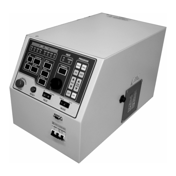
4. Front panel operation This section identifies and describes the various parts of the front panel. Limit and trip LED Power Knob Heat On/Off LEDs Mode Switch Program Indicators E-Stop Switch Volt, Curr and Freq Indicators Program Buttons Reset button Power Indicator Heat switch Figure 2: Front panel layout for model 3-135/400-3. -
Page 10: Heat On/Off Indicators
If any limit indicators are lit, the heat station components needs to be adjusted to obtain the required power (see section 6.1. on page 15). Trip indicators: These indicators are red in color and are lit if the unit is tripped. No power is being delivered to the load and the heat OFF indicator will be lit. -
Page 11: Mode Switch
4.8. MODE switch Identified by in Figure 2 on page 9. In the manual position, MAN, the power supply turns on with the HEAT switch and power level is controlled by the POWER POT. The programming the AUTO mode is done with the MODE switch in the MAN position. In the automatic position, AUTO, the power supply runs programmed jobs. -
Page 12: Feedback Selection
4.13. Feedback selection The feedback used by the power supply can be selected by setting a jumper on the control PCB as shown by Figure 3 on page 12. The default is input power feedback (right most position). Output voltage, auxiliary input, and inverter output current can also be selected. Due to the various forms of auxiliary feedback possible, several options are provided. -
Page 13: Programming In Auto Mode
5. Programming in AUTO mode The power supply can be programmed 12 separate heating profiles or jobs. Each profile can contain 25 steps. The duration of each step can be up to 640 seconds. 5.1. Entering a program 1. Turn on the power supply and put the MODE selector switch in MANUAL. 2. -
Page 14: Running A Program
5.3. Running a program 1. With the MODE selector in manual, press JOB to enter program mode. Press the JOB key to select the job you wish to run. Press enter (ENT). 2. To view the job parameters before running the job, press the STEP button will display the power and time for each step. -
Page 15: Load Station Tuning
6. Load station tuning. WARNING: Make sure that the circuit breaker is turned off before adjusting heat station components. This section describes the procedures for tuning the heat station so that full power will be obtained at the desired frequency. 6.1. -
Page 16: Changing The Heat Station Components
6.2. Changing the heat station components. This section describes the procedures for changing the heat station components. 6.2.1. Series inductor. The turn selector bar is identified by in Figure 4 on page 16. The near position selects zero turns and the far position eleven turns, as indicated in Figure 4 on page 16. Tighten the bar into position using the mounting screws. -
Page 17: Appendix A: User Interface
7. APPENDIX A: User Interface 7.1. Terminal Block 1 10V reference: This a 10V reference voltage for available for connecting to a potentiometer remotely. Terminal 1 to top of the pot, terminal 2 to the wiper and terminal 3 (ground) to the bottom of the pot. Remote Power Reference: When SW301, the INT/EXT switch is set to EXT, the voltage level at this terminal controls the command reference. -
Page 18: Appendix B: Tuning Examples
8. APPENDIX B: Tuning examples The following examples are intended as a guideline for tuning the power supply only. It is recommended that users add examples of their applications to this list as a reference future applications. Coil Caps ( Freq Power Voltage...
Need help?
Do you have a question about the 3-135/400-3W and is the answer not in the manual?
Questions and answers