
Summary of Contents for Ingram Engineering MPA685
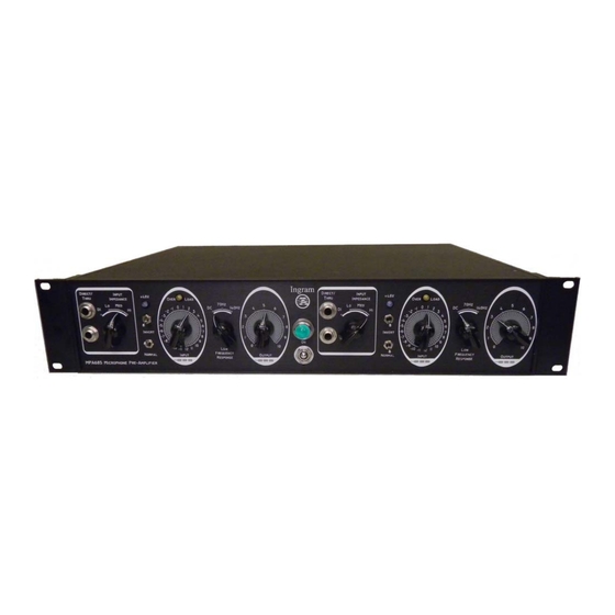
- Page 1 NGINEERING NGRAM MPA685 Dual Channel Microphone Preamplifier Owner’s Manual Option 201...
- Page 2 MPA685 Owner’s Manual 3/2012...
-
Page 3: Table Of Contents
MPA685 Owner’s Manual CONTENTS Introduction………..………………………………….……….……………………………. Description………………………………………………………………………………….. Block Diagram………………………………………………….………………………...… Safety Instructions…….……………………………………….…………..…………..…. Instructions for Use……………………………………………………….…………..….. 1. AC Power……………………………………………………………………….. 2. Turning Power On and Off…………………………………………………… 3. Audio Connections……………………………………………………….…… 4. Using the Audio Input / Microphone Impedance Selector……….…….. 5. Adjusting the Audio Input Level Settings…………………………………... -
Page 4: Introduction
Audio content can be input to the MPA685 via the balanced XLR input, pin 2 Hot, on the rear panel, or to the ¼” jack on the rear panel, labeled “Opt”, on your unit. The 1/4” jack is fully balanced. - Page 5 Extremely tight gain matching between channels, along with the transformer usage and discrete circuit design, also makes the MPA685 an excellent choice for stereo make-up gain applications.
-
Page 6: Block Diagram
MPA685 Owner’s Manual BLOCK DIAGRAM A block diagram of the MPA685 is shown below. BUFFER & POS/NEG BUFFER DIRECT PEAK INPUT DETECTOR OVERLOAD DIRECT LOOPTHRU +48V STEPPED SWITCH GAIN MIC Z STAGE BUFFER GAIN ATTN STAGE LOW FREQ OUTPUT OUTPUT... -
Page 7: Safety Instructions
MPA685 Owner’s Manual SAFETY INSTRUCTIONS 1. Read Instructions All the safety and operation instructions should be read before this product is operated. 2. Retain Instructions The safety and operating instructions should be kept for future reference. 3. Heed Warnings All warnings on the product and in these operating instructions should be followed. - Page 8 MPA685 Owner’s Manual 11. Servicing The user should not attempt to service this product beyond those means described in this operating manual. All other servicing should be referred to the Ingram Engineering Service Department. 12. Electric Shock To prevent electric shock, do not use this polarized plug with an extension cord, receptacle or other outlet unless the blades can be fully inserted to prevent blade exposure.
-
Page 9: Instructions For Use
MPA685 Owner’s Manual INSTRUCTIONS FOR USE 1. AC Power AC power is applied through an IEC 320-C16 (Male Pins) connector with earth ground. An AC fuse is contained in the connector. The fuse holder can be removed when AC power is unplugged from the unit. Use a flat blade screwdriver to remove the fuse holder from the unit. -
Page 10: Using The Audio Input / Microphone Impedance Selector
Some microphone manufacturers have explicit requirements for the load presented to the microphone, so the MPA685 impedance selector can also be used to guarantee that the microphone manufacturer’s requirements are met. -
Page 11: Adjusting The Audio Input Level Settings
MPA685 Owner’s Manual 5. Adjusting the Audio Input Level Settings After audio connections are made and the audio source is supplying signal, adjust the “Input” knob until the Overload LED lights infrequently, then, decrease the Input knob by one step. This maximizes the dynamic range of the audio. For maximum linearity, the Overload LED should never light. -
Page 12: Overload Led
MPA685 Owner’s Manual Attenuation / Gain Relative to Step Position "0" Attenuation / Gain Relative to Step Position "0" Attn Mode Gain Mode 65dB Total Adjustment Range 0dB = Reference -11 -10 Stepped Switch Position Figure 1: Attenuation or Gain vs. Stepped Switch Position 6. -
Page 13: Switch
MPA685 Owner’s Manual 7. +48V Switch +48V phantom power can be applied to microphones requiring it by turning the +48V switch to the up position. The +48V LED will light when the phantom power is On. When on, +48V regulated voltage is applied to both positive and negative balanced microphone input connections. -
Page 14: High Pass Filter
MPA685 Owner’s Manual AUDIO SPECIFICATIONS =+25°C unless otherwise noted) Parameter Unit Comments Microphone Input Impedance, Option 2 Low Setting Ω Medium Setting 1.5k Ω High Setting 2.5k Ω Instrument DI Input Impedance MΩ Direct input and loopthrough Nominal Gain, Input Impedance Option 2... -
Page 15: Ac Specifications
MPA685 Owner’s Manual Noise, <10 to 22 kHz BW, No Weighting Option 2 -123 Input Referred Overload Circuit LED Threshold LED illuminates at 1.0% THD Overload Circuit Bandwidth AC SPECIFICATIONS =+25°C unless otherwise noted) Parameter Unit Comments 115 / AC Voltage... -
Page 16: Care And Maintenance
MPA685 Owner’s Manual CARE AND MAINTENANCE 1. AC Fuse Use only a 500mA, Slow Blow fuse for replacement. The fuse is located in the AC inlet housing. A small flat blade screwdriver may be used to eject the fuse holder from the housing. -
Page 17: Troubleshooting
MPA685 Owner’s Manual TROUBLESHOOTING 1. Power does not turn on Verify that the rear panel master AC switch, if present on your option, is turned on. Check the AC fuse. The fuse holder can be removed when AC power is unplugged from the unit. -
Page 18: Contact Information
MPA685 Owner’s Manual If a multimeter is accessible, it can be used to check for AC or DC voltage on the DI cable shield coming from the instrument. Note that the impedance of a circuit connected to the direct instrument loop-through will be in parallel with the pre-amplifier Direct input 1 MegΩ... -
Page 19: Warranty Information
Failure to register the product will not void the three year warranty. Service and repairs of Ingram Engineering products are to be performed only at the factory OR at an authorized Ingram Engineering Service Center. Unauthorized service, repairs, or modification will void this warranty. - Page 20 Ingram Engineering product is still covered by the Three Year Limited Warranty. 3. Make sure the problem can be duplicated. If you bring your Ingram Engineering product to an Authorized Service Center and they can’t find anything wrong with it, you may be charged a service fee.
- Page 21 MPA685 Owner’s Manual This is your sole warranty. Ingram Engineering does not authorize any third party including any dealer or sales representative, to assume any liability on behalf of Ingram Engineering or to make any warranty for Ingram Engineering. THIS WARRANTY GIVEN ON THESE PAGES IS THE SOLE WARRANTY GIVEN BY...
-
Page 22: Important Notice
Tel: +1 (678) 685-9838 Ingram Engineering makes no warranty of any kind with respect to the material in this document and shall not be liable for errors contained herein or for incidental or consequential damages related to the use of the material.
Need help?
Do you have a question about the MPA685 and is the answer not in the manual?
Questions and answers