Table of Contents
Advertisement
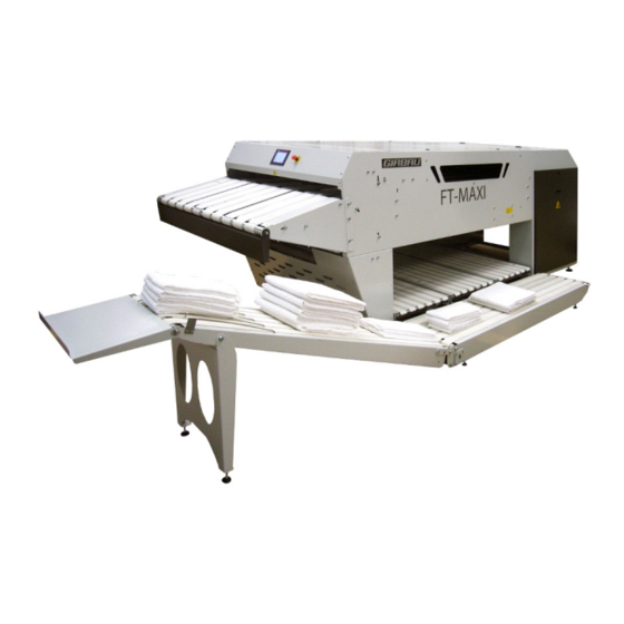
FT-MAXI
FOLDER
GIRBAU , SA
Crta de Manlleu, km.1
08500 VIC (Barcelona) .SPAIN
Tel. 34 93 8861100
Fax 34 93 8860785
girbau@girbau.es
www.girbau.com
USA et CANADA :
CONTINENTAL GIRBAU Inc.
2500 State Road 44
WI 54904 Oshkosh .USA
Tel. 34 93 8861100 1(920) 231-8222
Fax 1(920) 231-4666
info @continentalgirbau.com
www.continentalgirbau.com
FT-M1211A
5D000XX/F
Advertisement
Table of Contents

Summary of Contents for Giabau FT-MAXI
- Page 1 FT-MAXI FOLDER GIRBAU , SA USA et CANADA : Crta de Manlleu, km.1 CONTINENTAL GIRBAU Inc. 08500 VIC (Barcelona) .SPAIN 2500 State Road 44 Tel. 34 93 8861100 WI 54904 Oshkosh .USA Fax 34 93 8860785 Tel. 34 93 8861100 1(920) 231-8222 girbau@girbau.es...
- Page 2 Modele Series FT-MAX I From PLP243...
- Page 3 TECHNICAL MANUAL 1st part Genera ities, Installation, Fonctioning 2nd part separate Electrical and pneumatic schemas 3rd part separate Automation Translation of the original note FT-M1211A...
-
Page 4: Table Of Contents
6.2 Maintenance kit - FT-MAXI -2011-06 ..................36 6.3 Annual preventive kit of maintenance - FT-MAXI -2011-06 ............. 36 6.4 Maintenance kit - L5 - L6 - L7 - FT-MAXI -2011-02..............36 6.5 Maintenance kit - M5 - FT-MAXI -2011-02 ................37 6.5 Maintenance kit - M5 - FT-MAXI -2011-02 ................ - Page 5 09-0145 B (part 2) Kit ......................... 75 09-0147 A - 09-0165 A Kit ......................77 09-0148 A Kit ..........................79 09-0124F Kit ..........................81 4M05631 Shuttle LU450 ......................83 4M05646 Shuttle LU450 - Straps ....................83 4M05644 Shuttle LU450 - Kit 09-0146A ..................83 4M05601 Shuttle LU615 ......................
-
Page 6: Ce Declaration Of Conformity
CE DECLARATION OF CONFORMITY FT-M1211A... -
Page 7: Presentation
PRESENTATION 1.1 GENERAL PRECAUTIONS Conditions of use : It is IMPERITIVE that before any person begins to work with this machine or provides for its maintenance ( commissioning, maintenance, dismantling...), thoroughly reads and respects the entirety of the instructions contained within this manual, as well as those concerning the controls sections ( electric and pneumatic schemas). -
Page 8: Warnings
Do not try to remedy a jamming of the machine while the machine is running, which could lead to serious injuries. Place the main switch to the OFF position before any intervention on the machine. Do not turn on the machine until the problem has been resolved. Otherwise, damage to the mechanical .and electrical components could result. - Page 9 DANGER pictograms (yellow and black triangles) : General danger Electrical danger Mechanical danger Danger of falling Mechanical operations Pneumatic padlockable power DANGER zone (yellow and black band) Air suppy Air supply valve- padlockable FT-M1211A...
-
Page 10: Functioning Pictograms
1.4 FUNCTION PICTOGRAMS Emergency stop Main On/ Off switch These pictograms are found on the touch screen Stop Reset Use touch screen Lubricate with a grease gun Turn the selector to ON Turn the selector to OFF and padlock ( lock not supplied) Open the air supply valve Close the air supply valve and padlock ( lock not supplied) FT-M1211A... -
Page 11: Technical Characteristics
1.5 CARACTERISTIQUES TECHNIQUES ELECTRICITY Installed power 2,5 KVA Gauge in 230v tri 3 X 4mm²+gorund Gauge in 400v tri 3 X 2,5mm²+ground COMPRESSED AIR Maximum air pressure 10 bars Air supply hose diameter Ø15x21 6 bars avec baisse de pression Minimum air pressure temporaire de 0,5 bars maxi 1-2Nm3/100p... - Page 12 IM03019 - C FT-M1211A...
- Page 13 IM03064 - C FT-M1211A...
- Page 14 IM03065 - C FT-M1211A...
- Page 15 IM03066 - C FT-M1211A...
- Page 16 IM03151 - C FT-M1211A...
- Page 17 IM03152 - C FT-M1211A...
- Page 18 IM03153 - C FT-M1211A...
- Page 19 IM03154 - C FT-M1211A...
-
Page 20: Handling And Installation
2 HANDLING AND INSTALLATION 2.1 HANDLING The handling of the machine must be done by qualified personnel. During handing, nobody should be under the load. The machine must be handled using the hoist rings otherwise you risk in twisting the machine. Use the hoist rings intended for this procedure. -
Page 21: Installation
2.2 INSTALLATION The floor must be level and capable of supporting the weight of the machine. The machine must be put by level with regard to the ground - Connect the compressed air to the main air supply, which must be equipped with a shut off valve. - Page 22 Connecting to the electrical supply The electrical installation of the machine must only be performed by qualified personnel. - - Make sure that the supply voltage is correct and that the wattage of your system is sufficient before connecting the machine. The supply cable should be protected at the head of the line ( at the circuit breaker box) * Gauge 4 mm²...
-
Page 23: Testing
2.4 TESTING The testing of the machine should be conducted only by qualified personnel. The machine should be tested with all the types of articles before the machine is actually put into use. Assure that the first pieces of laundry are, if possible, second-rate articles in good condition. Once the installation is operational, management and maintenance staff should be trained so that they are familiarized with the machine. -
Page 24: Safety
3 SAFETY 3.1 GENERALITIES It is imperative that the Chapter 1 General Precautions be read and respected. Emergency Stop of the machine : - Press the button Emergency Stop : The machine remains in the position that it was in just prior to the moment it was stopped. The machine should be put back into operation only by the person in charge by pushing the reset button and is to do so only after having ensured that there is no longer any danger. -
Page 25: Intervention During Operation
3.3 INTERVENTION DURING OPERATION It is strictly forbidden to intervene while the machine is operating It is essentail that before any intervention the machine has come to a complete stop to: - Place the main ON/OFF selector in the OFF position and padlock it padlock not supplied - Close the air supply valve and padlock it. -
Page 26: Principles And Functioning
4 PRINCIPLES AND FUNCTIONING 4.1 PRINCIPLES Articles that can be folded : This is an independant machine for folding laundry. It is designed to fold ironed or wrung-out laundry such as terry cloth towels, dish towels, T-shirts, ect. These articles can be made out of terry cloth, linen, cotton and different types of polyester-cotton. -
Page 27: Functioning
4.2 FUNCTIONING Make sure that nobody puts their hands in the machine. Verify that all of the protections are in place and that nobody is working on top of or under the machine Before starting the machine, check: - The direction of rotation of the motors, - The air pressure, which should be 6 bars. - Page 28 Put the main switch into the OFF position. -Close the compressed air supply valve FT-M1211A...
-
Page 29: Maintenance Operations
5 MAINTENANCE PROCEDURES 5.1 GENERAL MAINTENANCE NOTE : Time of maintenance estimated are calculated for a person competent and formed in our machine. They are given as a rough guide, without engaging the responsibility of GIRBAU. Before any intervention: - Put the main switch in the OFF position and padlock it. - Close the compressed air-supply valve and padlock it. - Page 30 Every month or every 200 hours (Estimated time of maintenance : 2 hours including the previous regular maintenances) - Clean the compressed air treatment filter, see Chapter Maintenance of filter/ Regulator/ Air lubricator - Check the straps and their staples and replace those that are damaged - Pneumatic control : Pneumatic regulation of the stacker and shuttles stacker (elimination of the vibrations) Pressure of regulation of the reservoirs of air for the longitudinal foldings...
-
Page 31: Servicing Of The Filter / Regulator
5.2 SERVICING OF THE FILTER / REGULATOR GENERAL USAGE CONDITIONS Fitting and commissioning are to be carried out only by authorized trained personnel in accordance with the operating instructions. These products are intended for use exclusively with compressed air.They are not suitable for use with other media (fluids or gases). - Page 32 Fitting together with an already fitted service unit of the same series (_Fig. 2): 1.Remove the cover plates3on the sides to be fitted together (push upwards). 2.Place the module connectors MS4/6-MV4 in the grooves of the individual units. There must be a seal between the individual units.
- Page 33 5 CARE AND MAINTENANCE Condensate level approx. 10 mm below the filter element (_marking8). Filter/water separator empties automatically (manual emptying: Turn the drainage screw 9 in an anticlockwise direction as seen from below). The condensate will then flow out. Barbed fitting connection for tubing PCN-4-NT already fitted. Replace the filter cartridge if it shows signs of the following:: Low flow despite unmodified pressure setting.
- Page 34 6-.Complete re-commissioning of the MS4/6-LFR in accordance with the chapter “Commissioning”. MS4/6-LF/LFM/LFX: Commission the system again. Cleaning • Use only the following cleaning agents: – water or soap suds (max. +60 °C); – petroleum ether (free of aromatic compounds). Housing Die-cast aluminium Rotary knob PA/POM...
- Page 35 FESTO SPAB PRESSURE SENSOR PROGRAMMING 14-1051 1/ Connect the blue wire to the 0v (4). -the black wire to the pressure switch input -the brown wire to the +24v (3) Edit 2/ Set the pressure to 6 bars using the main pressure regulator. 3/ Press Edit .
-
Page 36: Spare Parts
Belt LA40 LG760 16-0882 Belt LA40 LG1125 16-0881 Belt LA40 LG2030 16-0876 Belt LA40 LG600 6.3 ANNUAL PREVENTIVE KIT OF MAINTENANCE - FT-MAXI - 2011 - 06 Référence Qté Description 2C02514 Stapled belt LA100/LG4760 2C01895 Stapled elastic cotton belt LA88 - LG831... -
Page 37: Maintenance Kit - M5 - Ft-Maxi -2011-02
6.5 MAINTENANCE KIT - L6 - L7 - FT-MAXI - 2011 - 07 Référence Qté Description 10-0401 Motor 250W/680Tr/208V/60Hz 10-0402 Motor brake 250W/680Tr/208V/60Hz B2 10-1210 Roll m otor cylindrical D80/L440 208V 13-3050 Contactor control m otor 13-3007 Start m otor 2,2/3,2A... - Page 38 Start m otor 1,1/1,6A 13-3000 Start m otor 0,28/0,4A 13-3050 Contactor control m otor 2D01906 Convex alu pulley D40/L59/D19 6.11 MAINTENANCE KIT - Q7 - Q9 - FT-MAXI - 2011 - 07 Référence Qté Description 10-1176 Motor 250W/680Tr/480V-60Hz 10-1177 Motor brake 250W/680Tr/230-400V-50Hz...
- Page 39 4M05681 Stacker flap ........................ 57 4M05954 Belt guide feeding table....................59 4M05698 Cross module meca ....................61 4M05613 Belt guide FT-MAXI ....................63 4M05699 Cross module straps ....................65 4M05619 Tubulure of blowing LG985 ..................67 4M05633 Cross module motor ....................69 4M05637 Liaison cross + Fold con + Feed con ................
- Page 40 FT-M 1211A...
-
Page 41: Exploded Views
8 EXPLODED VIEWS FT-M1211A... - Page 42 FT-M 1211A...
-
Page 43: 4M05675 Feeding Table
4M05675 FEEDER TABLE Reference Description 2S04691 Feeder table reinforcem ent 2T06879 Feeder table bib 2D01811 Motor spacer plate 2T06916 Counterflange 10-0360 Roller 51x2 W1400/1395 axle16xM10 10-0361 Chrom e roller 51x2 W1295/1285 axle 16xM10 4M05932 Motor roller 51x2x120 W1400 B55,5 2C01887 Felt strap 1CR stapled L95 W1730 16-0876 Belt LA40 LG600-TC35ER-JF1... - Page 44 FT-M 1211A...
-
Page 45: 4M05632 Feeding Table
4M05632 FEEDER TABLE L1 Reference Description 10-1279 Motor 250W-830Tr-208-240V - 60HZ 2D01812 Convex alu pulley D40/L59/D1L 2T07451 Motor flange 4M05632 FEEDER TABLE L5 Reference Description 10-0178 Motor 250W-680Tr-230-400V - 50HZ 2D01812 Convex alu pulley D40/L59/D1L 2T07451 Motor flange 4M05632 FEEDER TABLE L6-L7 Reference Description 10-0401... - Page 46 FT-M 1211A...
-
Page 47: 09-0031 Kit
KIT 09-0031 (PART 1) Description 14-0967 Distributor 14-0968 Silencer U-3/8 B FT-M1211A... - Page 48 FT-M 1211A...
-
Page 49: 4M05674 Frame
4M05674 FRAME Reference Description 3S01569 Cross support beam 2S04676 Right side fram e 2S04675 Left side fram e 2T06882 Left leg assem bly 2T06883 Right leg assem bly 2S04692 Cross brace 2T06956 Longitudinal cross brace 2T06891 Tem plate boom erang guard 2T06935 Back fram e brace 12-0393... - Page 50 FT-M 1211A...
-
Page 51: 4M05616 Folding Table
4M05616 FOLDING TABLE Reference Description 4M05622 Central table 2T06927 Plate L116/ W60/E2 2T06926 Sheet m etal cover L2779/W120/H20/E2 2T06931 Corner piece W20/H10/E1/L2600 FT-M1211A... - Page 52 FT-M 1211A...
-
Page 53: 4M05622 Central Table
4M05622 CENTRAL TABLE Reference Description 2T06929 Sheet m etal cover L2829/W440/H20/E2 2T06931 Corner piece W20/H10/E1/L2600 2T06926 Sheet m etal L2779/W120/H20/E2 2T06927 Plate L116/W60/E2 FT-M1211A... - Page 54 FT-M 1211A...
-
Page 55: 4M05975 Template
4M05975 TEMPLATE Reference Description 2D01821 Axle D25/L1394 2S04646 Left ski guide 2S04647 Right ski guide 2S04694 Left ski 2S04696 Right ski 10-0358 Ball-bearing bushing Øi25/Øe35/L40 2T07601 Arm support bracket V2 2T06801 GIO bracket 10-0200 Flange Ø20/2 holes 2S04645 Moving arm 10-0208 Clevis ball joint M10 03-0620 0385... - Page 56 FT-M 1211A...
-
Page 57: 4M05681 Stacker Flap
4M05681 STACKER FLAP Reference Description 10-0103 Bearing support braket 12 2S04727 Deposit flap right 2S04728 Deposit flap left 2D01828 Boss D20/W25/M10 10-0975 Sw ivel M10x1,2F 14-0894 Strut cylinder D32 C50 DF/AP 10-0208 Sw ivel M10 03-0620 0500 Galvanized threaded rod M10 L0500 10-0360 Roller 51x2 W1400/1395 Axle16xM10 11-0323... - Page 58 FT-M 1211A...
-
Page 59: 4M05954 Belt Guide Feeding Table
4M05954 BELT GUIDE FEEDING TABLE Reference Qty Description 2T07602 Sim ple belt guide 11-0324 Crosspiece PA66 D6,2x10 L35 FT-M1211A... - Page 60 FT-M 1211A...
-
Page 61: 4M05698 Cross Module Meca
4M05698 CROSS MODULE MECA Reference Qty Description 2T06989 Upper cross piece 3S01573 Left cross casing - electric 3S01574 Right cross casing - pneum atic 2T06946 Low er cross piece 4M05613 Strape guides 2T06947 Photocell support plate 12-0393 Footing bolt M16x100xD15 12-0394 Footing base PA D80 D15 2T03557... - Page 62 FT-M 1211A...
-
Page 63: 4M05613 Belt Guide Ft-Maxi
4M05613 BELT GUIDE FT-MAXI Reference Description 2T07188 Belt guide 11-0324 Crosspiece FT-M1211A... - Page 64 FT-M 1211A...
-
Page 65: 4M05699 Cross Module Straps
4M05699 TRANSVERSAL MODULE BELTS Reference Qty Description 4M05921 Motor roller 51x2x120 LG983 B55,5 2T07187 Table cross 10-0354 10 Roller 50x1,5 LG915/905 axle 14xM10 4M05922 Roller m otor 51x2x120 LG1295 B110 2D01811 15 Motor spacer plate 2T06949 Roller support plate 10-0557 Pulley plate D40 2T06955 Roller support plate... - Page 66 FT-M 1211A...
-
Page 67: 4M05619 Tubulure Of Blowing Lg985
4M05619 TUBULURE OF BLOWING LG985 Reference Qty Description 14-0885 Link auto Y-3/8-10 14-0506 Link top 3/8F 14-0492 Link sleeve 3/8F 2P03087 Sheet m etal 2D01824 Tubulure of blow ing FT-M1211A... - Page 68 FT-M 1211A...
-
Page 69: 4M05633 Cross Module Motor
4M05633 CROSS MODULE MOTO L1 Reference Qty Description 10-1278 Motor 250W-830TR 208-240V-60Hz/B24V 2T07451 Motor flange Ø135 2D01906 Convex alu pulley D40/L59/D19cl 10-1279 Motor 250W-830TR 208-240V-60Hz 4M05633 CROSS MODULE MOTO L5 Reference Qty Description 10-0177 Motor 230-400V-50Hz/B24V 2T07451 Motor flange Ø135 2D01812 Convex alu pulley D48/L59/D19cl 10-0178... - Page 70 FT-M 1211A...
-
Page 71: 4M05637 Liaison Cross + Fold Con + Feed Con
4M05637 LIAISON CROSS + FOLD CONV + FEEDER CONV Reference Description M aterial 2C02514 Stapled belt W100/L4760 Felt 2C01992 Stapled belt W180/L5985 Felt FT-M1211A... - Page 72 FT-M 1211A...
-
Page 73: 4M05640 Casing
4M05640 CASING Reference Qty Description 2T06881 Low er feeder table protection panel 12-0217 Hinge 2S04674 Cover guard 14-0688 Gas cylinder 13-0454 Security sw itch 16-0065 Sim ple elastic stop D25/M8 2T07011 Cabinet door 16-0049 Latch handle 2T06919 Top cover 2T06920 Central deflector 2S04687 Front protection guard... - Page 74 FT-M 1211A...
-
Page 75: 09-0145 B (Part 2) Kit
KIT 09-0145 B(PART 2) Reference Description 14-1017 Distribuidor MS6 14-1015 Filter MS6-LRB-1/2 14-1014 Filter MS6-LFR-1/2 14-1016 Bloc distribuidor MS6 14-0568 Silencer U-1-1/2B 14-1051 Pressure captor SPAB-P10R-G18-2P-M8 14-0527 Link 1/2 - M-F 14-1056 Distributor MS6-DL-1/2-Z FT-M1211A... - Page 76 FT-M 1211A...
-
Page 77: 09-0147 A - 09-0165 A Kit
KIT 09-0147 A KIT 09-0165 A Reference Description 14-0887 Pressure regulator MS6-LR-1/2-D6 14-0179 Tank 10L 14-0082 Valve 1/2 14-0084 Valve 14-0471 Link reduction 3/8M-1/8F 14-0473 Link reduction 1/2M-3/8F 14-0479 Link 1/2 M 14-0875 Link reduction 1M-1/2F 14-0989 Link auto F1/2-10/12 14-0524 Link 1/8M-F FT-M1211A... - Page 78 FT-M 1211A...
-
Page 79: 09-0148 A Kit
KIT 09-0148A Reference Description 14-0969 Iron sheet metal VMPA 14-0966 Electrodistribuidor VMPA 5/2 14-0988 Cable connexion VMPALSO B24 FT-M1211A... - Page 80 14-0184 FT-M 1211A...
-
Page 81: 09-0124F Kit
KIT 09-0124F Reference Description 14-0426 Link auto 1/4 - 8/10 2P02834 Base distributor 14-0184 14-0962 Link ring + nut 3/8 tube 14 2D01652 Link 14-1456 Distributor 15-0073 Cable connexion part EV type C FT-M1211A... - Page 82 FT-M 1211A...
-
Page 83: 4M05631 Shuttle Lu450
4M05631 SHUTTLE LU450 Reference Description 2T06897 Shuttle base LU0450 2C01901 Shuttle slide LU615 3S01567 Shuttle nose U 2D01847 Axle 6 Pans-17 W32-D8L19-M6 14-0819 Cylinder D25-C500 14-0429 Link auto M5-4-6 3D00856 Unidirectional roller W=435 3D00857 Unidirectional roller W=365 10-1222 Roller 20x1.5 W411/406 Axle 08xM5 10-0356 Roller 40x1.5 W445/435 Axle 12xM8 2C01902... - Page 84 FT-M 1211A...
-
Page 85: 4M05601 Shuttle Lu615
4M05601 SHUTTLE LU615 Reference Qty Description 2T06907 Shuttle base LU615 2C01901 Shuttle slide LU615 3S01572 Shuttle nose LU615 2D01847 Axle 6 Pans-17 W32-D8L19-M6 14-0819 Cylinder D25-C500 14-0429 Link auto M5 4-6 3D00850 Unidirectional roller LU=600 3D00851 Unidirectional roller LU=530 10-1221 Roller 20x1.5 L576/571 AXLE08xM5 10-0347 Roller 40x1.5 L610/600 AXLE 12xM8... - Page 86 FT-M 1211A...
-
Page 87: 4M05923 Unidirectional Roller Lu=600
4M05923 UNIDIRECTIONAL ROLLER LU=600 Reference Description 2D01850 Axle D15 L610 2D01851 Tube D38/L600 16-0021 D38 0545 Drum covering auto W50 rough grey 10-0312 Bearing 15x35x11 10-1216 Bearing 15x35x11 free w heel 4M05924 UNIDIRECTIONAL ROLLER LU=530 Reference Description 2D01852 Axle D15 L610 2D01851 Tube D38/L600 16-0021 D38 0545... - Page 88 FT-M 1211A...
-
Page 89: 4M05925 Unidirectional Roller Lu=435
4M05925 UNIDIRECTIONAL ROLLER LU=435 Reference Description 2D01834 Axle D15 L445 2D01853 Tube D38/L435 16-0021 D38 0545 Covering spur w hite W50 10-0312 Bearing 15x35x11 10-1216 Bearing 15x35x11 free w heel 4M05926 UNIDIRECTIONAL ROLLER LU=365 Reference Description 2D01836 Axle D15 L375 2D01837 Tube D38/L365 16-0021 D38 0545... - Page 90 FT-M 1211A...
-
Page 91: 4M05947 Discharge Conveyor
4M05947 DISCHARGE CONVEYOR Reference Qty Description 2T06903 Com m on discharge conveyor fram e 2T07702 Discharge conveyor liaison tie spacer 2T06902 Upper discharge conveyor frame 2T06901 Discharge conveyor base support 10-0363 Roller 50x1.5 L436/426 axle 14xM10 2T06905 Discharge conveyor clearance 12-0397 Foot bolt M8x60xD10 12-0396... - Page 92 FT-M 1211A...
-
Page 93: 4M05977 Storage Tray Options
4M05977 STORAGE TRAY OPTION Reference Qty Description 2T06900 Discharge conveyor storage tray 2C01934 Conveyor fingers 15-0162 Photocell E3Z-LS86 15-0190 M8 right 10m 2T03557 Cell support E3Z FT-M1211A... - Page 94 FT-M 1211A...
-
Page 95: 4M05749 Conveyor With Free Rolls Option
4M05749 CONVEYOR WITH FREE ROLLS OPTION Reference Description 4M00964 Free roll 1500x53 4M01236 Height free roll 460-940 4M04337/530 Roll LA530 15-0034 Photocell E3Z 15-0048 Reflector 15-0190 Connexion part M8 right 10m 2T03144 Reflector support 60x90 2T03557 Cell support E3S 4M01239 Buffer D530m m FT-M1211A... - Page 96 FT-M 1211A...
Need help?
Do you have a question about the FT-MAXI and is the answer not in the manual?
Questions and answers