Freefly Alta Setup Manual
Hide thumbs
Also See for Alta:
- User manual (106 pages) ,
- Setup manual (40 pages) ,
- Aircraft flight manual (114 pages)
Table of Contents
Advertisement
Quick Links
Advertisement
Table of Contents

Related Manuals for Freefly Alta


Summary of Contents for Freefly Alta
- Page 1 SETUP GUIDE RE V ISION A | 7.24.2015...
- Page 2 WWW.FREEFLYSYSTEMS.COM | SETUP GUIDE...
-
Page 3: Table Of Contents
13 Folding ALTA 26 Compass Calibration 14 Installing a Radio Receiver 27 Control Modes 16 Failsafe and Loss of Signal 30 Arming and Starting ALTA Motors 18 Installing a Battery 32 Tuning ALTA 20 Status Light 33 Setting Hover Throttle 21 Orientation Lights 34 Attaching a MōVI... -
Page 4: Disclaimer And Warning
» Always remove the Configuration Jumper when making changes to the configuration of ALTA . » ALTA is not a toy and should be operated with extreme care, as improper operation can cause damage to property, serious » Always test ALTA with the propellers removed to make sure that personal injury or death. - Page 5 FREEFLY FOR SUCH PRODUCT. NOT WITHSTANDING ANY THING HEREIN, » Use of third-party products on ALTA . IN NO E VENT SHALL FREEFLY ’S LIABILIT Y FOR ALL CL AIMS ARISING OUT » Use of ALTA in a physically or mentally OF OR REL ATING TO THIS AGREEMENT E XCEED THE AMOUNTS PAID BY impaired capacity.
- Page 6 BOOM NUMBERING AND PROP ROTATION (OVERHEAD VIEW) BOOM 1 – Clockwise BOOM 2 – Counter-Clockwise BOOM 3 – Clockwise BOOM 4 – Counter-Clockwise BOOM 5 – Clockwise BOOM 6 – Counter-Clockwise WWW.FREEFLYSYSTEMS.COM | SETUP GUIDE...
-
Page 7: Introduction
This Setup Guide has been prepared to highlight the operation of basic airframe and flight control systems. It is supplemental to the ALTA User Manual, which contains all the information required to set up, operate and maintain an ALTA system safely. Do not operate ALTA without completely reading the User Manual found at www.freeflysystems.com/software-manuals/. - Page 8 ALTA OVERVIEW 1. GPS/Compass/Wi-Fi Module/microSD Card 6. Boom Retention Clip 2. Propeller 7. Isolator Cartridge 3. Boom 8. Motor 4. Boom Latch 9. Battery Pack (Not Included) 5. Inverted Landing Gear 10. Battery Retention Strap TOP MOUNT CONFIGR ATION WWW.FREEFLYSYSTEMS.COM...
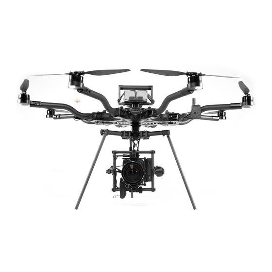
- Page 9 11. Status Light 16. FPV Camera Mount 12. Orientation Light 17. Handle 13. Toad In The Hole Adapter 18. Power Leads 14. MōVI & Camera (Not Included) 15. Landing Gear (Not Included) BOT TOM MOUNT CONFIGR ATION WWW.FREEFLYSYSTEMS.COM | SETUP GUIDE...
- Page 10 WWW.FREEFLYSYSTEMS.COM | SETUP GUIDE...
- Page 11 UNBOXING ALTA 1. Case 10. Fasteners 2. ALTA a. (4) M3 × 8 Socket Head for Toad In The Hole Male Adapter 3. Case Lid Foam b. (2) M3 × 8 Flat Head for Accessory Mount 4. Isolator Cartridges 11. Toad In The Hole Male Adapter a.
-
Page 12: Unfolding Alta
UNFOLDING ALTA 1. Remove ALTA from case 2. Fold down all six boom retention clips 3. Open ALTA booms 4. Snap shut all six boom latches until they “click” 6. Visually confirm all latches are seated properly 5. Remove prop protectors WWW.FREEFLYSYSTEMS.COM... -
Page 13: Folding Alta
FOLDING ALTA 1. Secure props with prop protectors 2. Unlatch all six booms 3. Close ALTA booms 4. Fold up all six boom retention clips to secure booms WWW.FREEFLYSYSTEMS.COM | SETUP GUIDE... -
Page 14: Installing A Radio Receiver
INSTALLING A RADIO RECEIVER 1. Locate the noted closeout panels used for receiver installation (between booms 1 & 2 and 5 & 6) 2. Remove side closeout panel with radio wires using a 1.5mm hex driver 3. Identify required wire 4. - Page 15 BINDING A RADIO RECEIVER Refer to the instructions provided with your 7. Attach receiver/satellite to exterior using the provided double sided tape: radio controller to complete the binding process. a. Futaba & PPM receiver For Spektrum/JR radios, a receiver is required to bind the satellites to a radio controller.
-
Page 16: Failsafe And Loss Of Signal
Setting failsafes in the receiver is not necessary, as failsafe behavior radio controller is powered off. is set in the ALTA App. The radio’s failsafe settings will not be used. PPM RECEIVERS When using a receiver with a PPM output signal, the Synapse Flight... - Page 17 WE RECOMMEND THE FOLLOWING FAIL SAFE SE T TINGS: 1. Throttle: Neutral 2. Pitch/Roll/Yaw: Neutral 3. Flight Mode Switch: Position Mode 4. Home Switch: Return to Home POSITION HEIGHT R.T.H. MANUAL RIGHT STICK LEF T STICK WWW.FREEFLYSYSTEMS.COM | SETUP GUIDE...
-
Page 18: Installing A Battery
INSTALLING A BATTERY WARNING See warning on page 19. BOT TOM MOUNT 1. Place battery retention strap studs at the appropriate height for CAUTION battery pack(s) See cautions on page 19. 2. Adjust battery stops to fit battery pack(s) 3. Attach the single-hole end of the battery retention straps to the studs 4. - Page 19 Positive is indicated by a red power lead, and negative/ground is indicated by a black power lead. 3. Place battery packs(s) in landing gear Reversing polarity will damage ALTA’s electronics. 4. Tension and secure battery retention straps CAUTION When installing two battery packs, ensure they are at a similar state of charge (a full pack voltage difference less than 0.5V).
-
Page 20: Status Light
BOOTING Flashing Red + White Flight controller is booting The rear-facing Status Light shows the status of ALTA as it boots, arms and flies. The following table shows the different Flashing White Flight controller is running and ready to arm meanings of the light in the various flight phases. -
Page 21: Orientation Lights
MEANING BOOTING Blue ESC booting The boom-end mounted Orientation Lights indicate both the orientation of ALTA in flight and the status of the individual S TA NDBY Flashing green ESC booted normally motor Electronic Speed Controllers (ESCs) during other flight phases. The following table shows the different... -
Page 22: Configuration Jumper
CONFIGURATION JUMPER A small jumper is used to prevent motor operation while configuring radio mapping parameters. With the jumper in place, the motors may operate, but channel mapping is prevented. With the jumper removed, channel mapping may take place, but the motors will be turned off. 1. -
Page 23: Alta App
ALTA APP NOTE When making configuration changes with the ALTA App, wait three seconds for the app to automatically save changes to ALTA. The ALTA App is used to configure ALTA parameters and to monitor ALTA’s status during flight. To download the ALTA App, search for “Freefly ALTA”... -
Page 24: Mapping Channels
1. Remove the Configuration Jumper (see page 22) Ensure proper channel mapping prior to flight. Incorrect mapping 2. Power ALTA using a battery pack or by plugging in the included can lead to immediate loss of control. USB-Futaba cable into an available port on a Futaba receiver 3. -
Page 25: Arm Enable Switch
2 (MIDDLE) Possible Possible ground handling or disarming during flight. To set up an Arm Enable Switch, refer to Mapping Channels or the ALTA User Manual. Not Possible Possible If used, the Arm Enable function should be mapped to a three-position switch. -
Page 26: Compass Calibration
COMPASS CALIBRATION WARNING Verify ALTA is disarmed prior to performing a compass calibration. To ensure ALTA does not arm, set the Arm ALTA features a highly sensitive 3-axis magnetometer that measures the Enable Switch (if available) to disable, and remove the earth’s magnetic field to infer heading. -
Page 27: Control Modes
HEIGHT MODE Height Mode changes the throttle stick behavior to command climb and descent rates. The higher the throttle stick position, the faster ALTA will climb. Conversely, the lower the throttle stick position, the faster ALTA will descend. When the throttle stick is centered, ALTA will enter Height Hold. In Height Hold, ALTA will maintain a target altitude and try to correct for drift. - Page 28 It only occurs if Autoland is selected as the Safe Height. If it is lower, it will climb to Safe Height, and if ALTA is Loss of Signal (LOS) event in the ALTA App, or at the end of an LOS above Safe Height, it will remain at its current altitude.
- Page 29 RADIO LOSS OF SIGNAL SAFE HE IGH T IS US ER D E FI NE D ALTA App > Configurations > Safety > Safe Height WWW.FREEFLYSYSTEMS.COM | SETUP GUIDE...
-
Page 30: Arming And Starting Alta Motors
ARMING AND STARTING ALTA MOTORS TO ARM ALTA 1. Ensure ALTA is powered on and is in Standby Mode 2. Select Manual Mode using the radio controller’s mode switch 3. Set the radio controller’s home switch to the middle position 4. - Page 31 Always check the ALTA and its components prior to operation. WARNING CAUTION Always maintain a safe distance from the ALTA when in use. Motors can be disabled in flight if Do not attempt to disarm motors in Height or Never attempt to touch the ALTA when the propellers are moving.
-
Page 32: Tuning Alta
Tuning can change the fundamental flying characteristics of ALTA . It is possible for ALTA to become unstable or even uncontrollable ALTA comes pre-tuned for a wide variety of payloads and flying conditions. if values are set too high or too low. Only change tuning parameters Generally, additional tuning is not required to fly ALTA, and additional tuning in small increments and with caution. -
Page 33: Setting Hover Throttle
Adjust the Hover Throttle setting by entering a stable hover in Manual Mode. Note the ALTA is flying. stick position, or have an assistant view the radio chart in the ALTA App to determine stick position. If ALTA hovers with the stick below neutral, decrease the Hover Throttle until ALTA hovers with neutral stick input. -
Page 34: Attaching A Mōvi
ATTACHING A MōVI A MōVI can be attached to either the top or bottom of the ALTA via the Freefly Toad In The Hole (TITH) Quick Release. ALTA comes pre-configured for bottom mounting a MōVI. BOT TOM MOUNT 1. Prepare your MōVI for bottom-mount flight (see MōVI manual) a. - Page 35 CAUTION Top mounting is not supported by the MōVI M10. ADDING A TITH TOP MOUNT 1. Prepare your MōVI for top-mount flight a. Remove landing gear (see MōVI manual) b. Install TITH receiver on MōVI (see MōVI manual) 2. Connect and secure the supplied inverted landing gear to the bottom Toad 3.
- Page 36 W W W.FREEFLYSYSTEMS.COM MōVI is a registered trademark in the U.S. Pat. & Tm. Office. FREEFLY, the wing logo, and A LTA are trademarks of Freefly Systems Inc. Apple and the Apple logo are trademarks of Apple Inc., registered in the U.S. and other countries. App Store is a service mark of Apple Inc.
Need help?
Do you have a question about the Alta and is the answer not in the manual?
Questions and answers