Table of Contents
Advertisement
Advertisement
Table of Contents

Related Manuals for B&B VESR901

Summary of Contents for B&B VESR901
- Page 1 VESR9xx Serial servers...
- Page 2 International Headquarters B+B SmartWorx. 707 Dayton Road Ottawa, IL 61350 USA Phone (815) 433-5100 -- General Fax (815) 433-5105 Website: www.bb-smartworx.com support@bb-smartworx.com European Headquarters B+B SmartWorx Westlink Commercial Park Oranmore, Co. Galway, Ireland Phone +353 91-792444 -- Fax +353 91-792445 Document: VESR9xx _3615m...
-
Page 3: Table Of Contents
SERIAL SERVER SETUP AND CONNECTIONS ............17 CONNECTING THE POWER SUPPLY ................17 CONNECTING VES R9XX SERIA L SERVERS TO SERIAL DEVICES ......... 18 CONNECTING THE VESR901-X ................. 19 CONNECTING THE VESR902T-X ............... 19 CONNECTING THE VESR902D-X ..............20 CONNECTING VES R9XX SERIA L SERVERS TO A NETWORK ........21 NETWORK CONNECTION (10BASET/100BASETX) ........ - Page 4 BAUD RATE ........................28 CHARACTER COUNT ..................... 28 CONFIGURATION FILES ....................28 DATA/PARITY/STOP ..................... 28 DEFAULT GATEWAY ..................... 29 DELIMITER 1, DELIMITER 2 AN D DELIMITER REMOVAL ........... 29 DELIMITER 1 ......................29 DELIMITER 2 ......................29 DELIMITER REMOV AL ..................29 HOW DELIMITERS WORK ..................
- Page 5 Appendix C: Dimensional Diagrams ................ 51 APPENDIX D: CONNECTOR PINOUTS ............... 55 VESR901 & VESR921 SERIES ................55 VESR902D SERIES ....................57 VESR902T & VESR922T SERIES................ 58 STANDARD ETHERNET CABLE RJ-45 PIN-OUT ..........59 B&B SMARTWORX TECHNICAL SUPPORT ........... 60...
-
Page 6: Introduction
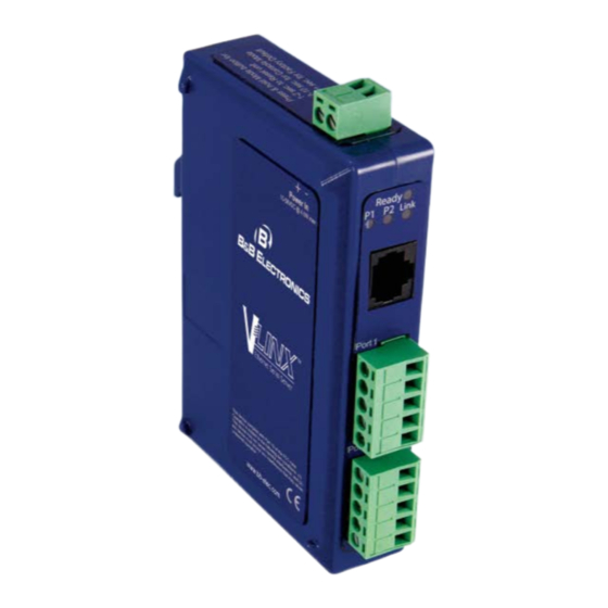
INTRODUCTION Thank you for purchasing a VESR9xx Serial Server product! This product has been manufactured to the highest standards of quality and performance to ensure your complete satisfaction. A VESR902T Serial Server ABOUT VESR9XX SERIAL SERVERS VESR9xx Serial Servers connect serial devices (RS-232, RS-422 or RS-485) to Ethernet networks, allowing the serial device to become a node on the network. -
Page 7: Vesr9Xx Serial Server Model Numbering
VESR9XX SERIAL SERVER MODEL NUMBERING VESR9xx Serial Server are a growing family of products. Models are available with one or two serial connections and one or two Ethernet connections. Network connection options include 10BaseT/100BaseTX copper or several different fiber optic options (on models with a pass-through port, the pass-through port is copper). The following diagram shows the model numbering scheme:... -
Page 8: List Of Vesr9Xx Serial Server Models
LIST OF VESR9XX SERIAL SERVER MODELS The following table lists the various VESR9xx Serial Server models available. Model Number Features VESR901 Vlinx , 1PORT, DB9, ESS, DIN, CU ETHERNET VESR901-SC40 Vlinx , 1PORT, DB9, ESS, DIN, FIBER, SC, 40KM VESR901-SC80... - Page 9 Model Number Features VESR921-ST80 VLINX, 1PORT, DB9, ESS, DIN, FIBER, ST, 80KM, CU VESR922T VLINX, 2PORT, TB, ESS, DIN, 2 CU ETHERNET VESR922T-MC VLINX, 2PORT, TB, ESS, DIN, FIBER, MULTI, SC, CU VESR922T-MT VLINX, 2PORT, TB, ESS, DIN, FIBER, MULTI, ST, CU VESR922T-SC VLINX, 2PORT, TB, ESS, DIN, FIBER, SC, CU VESR922T-SC40...
-
Page 10: Vesr9Xx Serial Server Features
VESR9XX SERIAL SERVER FEATURES Three series models VESR9x1-x (single serial port) VESR9x2D-x (two serial ports with DB9M) VESR9x2T-x (two serial ports with pluggable terminal blocks) Fiber models available for each of the above series Ethernet pass through ports are available on VESR92x series models. Multi-interface serial ports DB-9M and pluggable terminal block serial port connector options All ports are software selectable as RS-232, RS-422 or RS-485 2- and 4-wire... -
Page 11: Vesr9Xx Serial Server Hardware
VESR9XX SERIAL SERVER HARDWARE VESR9xx Serial Servers are enclosed in DIN rail mountable enclosures and feature LED indicators, power, Ethernet and serial connectors and a recessed Mode switch. PACKAGE CHECKLIST VESR9xx Serial Servers are shipped with the following items included: VESR9xx Serial Server Module Quick Start Guide VESR9XX SERIAL SERVER ENCLOSURES AND MOUNTING... -
Page 12: Led Indicators(Vesr90X)
LED is off, it indicates the system is not operating correctly. SERIAL PORT LEDS VESR901-x serial servers feature one serial port. VESR902D,and VESR902T-x serial servers feature two serial ports. Each serial port has an associated LED. Serial Port LEDs blink (green) when data is being transmitted or received on the serial port. -
Page 13: Mode Switch
LEDs on 1 and 2 Port Serial Servers E1 and E2 LEDs The E1 and E2 LEDs illuminate (green) if the Ethernet connection is operating in 100BaseTX mode. The LEDs are off if the mode is 10BaseT. When the LED is blinking it indicates that there is data traffic on the Ethernet link. -
Page 14: Ethernet Connector
Top View of the Serial Server The Mode switch can be used to: Initiate a Hardware Reset Enter Console Mode Reload factory defaults Note: Refer to Section 3. Serial Server Setup and Connections for more information on using the Mode switch. ETHERNET CONNECTOR Serial server models using 10BaseT/100BaseTX network connections use an RJ45 receptacle. -
Page 15: Fiber Optic Connectors
VESRxx Serial Servers use three serial port connector configurations, depending on the model: VESR901-x serial servers feature one serial port and use a DB-9M connector for RS- 232 and a five-position removable terminal block for RS-422 and RS-485 connections. VESR902D-x serial servers feature two serial ports, both using DB-9M connectors for RS-232, RS-422 and RS-485 connections. -
Page 16: Power Connector
Five-Position Pluggable Terminal Blocks Note: Refer to Appendix D for connection pin-outs. POWER CONNECTOR The power connector is a 5.08 mm 2-position pluggable terminal block. Power Connection... -
Page 17: Mounting Hardware
MOUNTING HARDWARE VESR9xx Serial Server modules can be DIN rail mounted. The DIN mounting clip and spring is included on each module. DIN Clip on a Serial Server Module SERIAL SERVER SETUP AND CONNECTIONS This section describes how to setup and connect VESRxx Serial Servers. Note: In this section devices to be connected to the serial server’s serial connection are simply referred to as the “serial device”. -
Page 18: Connecting Vesr9Xx Serial Servers To Serial Devices
CONNECTING VESR9XX SERIAL SERVERS TO SERIAL DEVICES VESR9xx Serial Servers can be configured to connect to serial devices using RS-232, RS-422, RS-485 2-wire and RS-485 4-wire. RS-232 connections support eight signal lines plus Signal Ground. Signals are single ended and referenced to Ground. Default communications parameters are 9600, 8, N, 1 and no flow control implemented. -
Page 19: Connecting The Vesr901-X
If you select RS-232 mode when you configure the serial server, you must connect the serial device to the serial server via a serial cable. The VESR901 is a DTE. If the serial device is a DTE, use a null modem (cross-over) cable. If the serial device is a DCE, use a straight-through cable. -
Page 20: Connecting The Vesr902D-X
VESR902T-x Connections CONNECTING THE VESR902D-X The VESR902D-x has two serial connections that support RS-232, RS-422 and RS-485 (2- and 4-wire). The unit has two connectors, both of which are DB-9M connectors. You must connect the serial device to the serial server via a serial cable. The VESR902D is a DTE. -
Page 21: Connecting Vesr9Xx Serial Servers To A Network
CONNECTING VESR9XX SERIAL SERVERS TO A NETWORK NETWORK CONNECTION (10BASET/100BASETX) When connecting a serial server equipped with a 10BaseT/100BaseTX network connection (RJ45 connector) a standard network cable is connected from the serial server to a network drop. PCs configuring and/or communicating with the serial server are also connected to the network. -
Page 22: Vesr9Xx Serial Server Configuration Connections
VESR9XX SERIAL SERVER CONFIGURATION CONNECTIONS VESR9xx Serial Servers can be configured over the network or via a serial port. CONFIGURING THE VESR9XX SERIAL SERVER VIA THE NETWORK CONNECTION When configuring via the network, either Vlinx Manager software or the web interface can be used. -
Page 23: Configuring The Vesr9Xx Serial Server Via The Serial Port (Console Mode)
CONFIGURING WITH THE WEB INTERFACE VESR9xx Serial Servers can be configured over the network using a standard internet browser such as Internet Explorer or Firefox. To open the web configuration interface: 1. On a PC connected to the network, open a browser. In the browser’s address bar, type the IP address of the serial server. -
Page 24: Vesr9Xx Serial Server Operational Connections
The serial server is in Console Mode when: On the VESR901: Port 1 LED is On and the Ready LED is Off. On VESR902x models: Port 1 LED is On and the Port 2 LED is Off. To configure the serial server, open the Vlinx Manager software and set up the serial server's parameters as required. -
Page 25: Using Vesr9Xx Serial Servers In Direct Ip Mode
USING VESR9XX SERIAL SERVERS IN DIRECT IP MODE A Direct IP connection allows applications using TCP/IP or UDP/IP socket programs to communicate with the COM ports on the serial server. In this type of application the serial server is configured as a TCP or UDP server. The socket program running on the PC establishes a communication connection with the serial server. -
Page 26: Using Vesr9Xx Serial Servers In Paired Mode
new COM port, it communicates directly with the remote serial device connected to the serial server. To set up a Virtual COM Port Mode connection: 1. Connect the serial server to the network and a serial device as described in previous sections. Configure the serial server for VCOM operation (using Vlinx Manager). -
Page 27: Initiating A Hardware Reset On The Serial Server
The serial server is in Reset Mode when: On the VESR901: Port 1 LED is On and the Ready LED is Off. On VESR902x models: Port 1 LED is On and the Port 2 LED is Off. The LEDs go back to their normal states when the device resumes normal operation. -
Page 28: Description Of Serial Server Properties
DESCRIPTION OF SERIAL SERVER PROPERTIES The following serial server properties are ordered alphabetically to assist you in finding the information you need. BAUD RATE Baud Rate is the communication speed of the link between the serial server and the device attached to its serial port. Both these devices must be configured to operate at the same baud rate. -
Page 29: Default Gateway
The number of Data bits, type of Parity and number of Stop bits selected define the serial port parameters at which the serial server will operate. These parameters must be configured to match the parameters set on the serial device connected to the serial server's serial port. -
Page 30: How Delimiters Work
Delimiter Removal controls removing of Delimiter 1 and Delimiter 2 from the received characters before the received characters are sent to the network. HOW DELIMITERS WORK When only Delimiter 2 (the end delimiter) is enabled, characters received by the serial port are accumulated in a buffer. When the end delimiter is received on the serial port, the buffered characters, including the end delimiter, are sent to the network. -
Page 31: Firmware Version
A dynamic address assigned by the DHCP server may change if the server loses the Ethernet connection or power is removed. If a device on the network that normally communicates with the serial server is configured to communicate with a specific IP address of the serial server, and the IP address has been changed, the device will not be able to communicate with the serial server. -
Page 32: Ip Address
the number of network packets, but increase the amount of time to receive characters. Smaller values may increase the number of network packets, but decrease the amount of time to receive characters. The range is 1 through 65535. IP ADDRESS Software or hardware attempting to access the serial server via the network must know the IP Address of the server. - Page 33 Use the Vlinx™ Manager Software to search for, discover, and configure the unit. 2. Method Two: Change the serial server’s network setting to match your PC using Console Mode Connect a null modem serial cable (crossover cable) from Port 1 on the serial server to an available COM port on your PC.
-
Page 34: Link Status
h. Un-check the box next to “I want DHCP to setup the Network.” Re-configure the serial server’s Network Settings to something within the range of your PC’s Network Setting. For example If your PC is configured to: IP Address = 192.168.0.1 Network Mask = 255.255.255.0 Default Gateway = 192.168.0.100 Configure the serial server to:... -
Page 35: Model
MODEL The Model number of the currently selected serial server is displayed on the Login page of Vlinx Manager. NETWORK PROTOCOLS Network Protocols available for use on VESR9xx serial servers include TCP, UDP, VCOM and Paired Mode. NETWORK WATCHDOG Network Watchdog controls the duration of network inactivity when a network connection is determined idle and causes the connection to be forced closed. -
Page 36: Password
for connections and set the maximum (up to four) number of simultaneous connections it will accept. You can filter the connections it will accept based on specific IP addresses or ranges of IP addresses that you specify. PASSWORD When you first receive the VESR9xx serial server from the factory the Password is blank so that you can initially access the serial server without entering a value into this field. -
Page 37: Serial Server Name
It must not consist of all numeric values. SERVER SERIAL PORT NUMBER The Server Serial Port Number of the currently selected port is shown in this field. VESR901-x serial servers feature one serial port. VESR902D-x and VESR902T-x serial servers feature two serial ports. SERIAL WATCHDOG Serial Watchdog controls the duration of serial inactivity when the serial port is determined idle and causes all connections for that serial port to be forced closed. -
Page 38: Tcp (Transmission Control Protocol)
For a Class D network (IP addresses 224.0.0.0 through 239.255.255.255) and Class E Networks (IP addresses 240.0.0.0 through 255.255.255.255) the subnet mask is ignored. VESR9xxserial servers come from the factory with a default subnet mask value of: 255.255.255.0 TCP (TRANSMISSION CONTROL PROTOCOL) TCP (Transmission Control Protocol) provides reliable connection-oriented network communication with error checking. -
Page 39: Vcom (Virtual Com Port)
Specific IP addresses and UDP port numbers. (This is called unicast.) A range of IP addresses and UDP port numbers. (This is called unicast range.) You can also configure the serial server to receive from nodes on the network using the same list of configuration options. -
Page 40: Downloading Firmware Files
The name of the currently selected serial server appears in the top drop down list. Other serial servers (that have already been discovered) can be selected from the drop down list, if desired. The current firmware version of the selected serial server is shown in the text below the serial server name. - Page 41 Progress Bar and Progress Box provides information on the progress of the transfer. In the Firmware File drop down list, select the firmware file to upload to the serial server. Click Upgrade. The Progress box and Progress bar display information on the upgrading process.
-
Page 42: Diagnostics
DIAGNOSTICS Clicking the Diagnostics icon opens the Diagnostics dialog box and enables you to check the operation of connected serial servers and VCOM ports on the local computer. The Computer Information box displays information about the type of network connections, the IP addresses, Subnet Masks and Default Gateways in use. Diagnostics Dialog Box TESTING A SERIAL SERVER CONNECTION... -
Page 43: Testing A Virtual Com Port
To run diagnostics on a serial server: 1. Click the Diagnostics icon. dialog box appears. Diagnostics Select the option: a serial server In the drop down box select the specific serial server you want to check. Click the Start button Information about the progress of the pinging process is displayed in box. - Page 44 To run diagnostics on a virtual COM port: 1. Click the Diagnostics icon. dialog box appears. Diagnostics Select the option: a virtual communications port In the drop down box select the specific COM port you want to check. Click the Start button. Information about the progress of the pinging process is displayed in the box.
-
Page 45: Appendix A: Default Server Settings
APPENDIX A: DEFAULT SERVER SETTINGS Setting Default Value Server Name MODEL NUMBER Serial Number printed on side of unit Password password field is blank from factory DHCP Enable IP Address BASED ON DHCP SERVER If a DHCP assignment is not available, the device will default to 169.254.102.39 Net Mask 255.255.255.0... -
Page 46: Appendix B: Product Specifications
APPENDIX B: PRODUCT SPECIFICATIONS GENERAL SPECIFICATIONS Device Serial Server Hardware and included accessories CD with Vlinx Manager software for Windows 2000, XP (32/64 bit), 2003 Server (32/64 bit), Vista (32/64 bit), 2008 Server (32/64 bit), Windows 7 (32/64 bit) Optional Accessories Cable 232NM9 Null Modem Crossover Cable for DTE to DTE connection... - Page 47 Power Consumption VESR90x – 4.0W (max) VESR92x – 6.0W (max) Wire Size 28 to 16 AWG Wire Type Copper Wire Only Tightening Torque 5 KG-CM Terminal Blocks Wire Temp Rating 105 °C Minimum Sized for 60 °C Ampacity Note: One Conductor Per Terminal...
-
Page 48: Controls, Indicators And Connector Specifications
CONTROLS, INDICATORS AND CONNECTOR SPECIFICATIONS Switches Reset button Hold in for 0 to 2 seconds for hardware reset Hold in for 2 to 10 seconds for Console Mode (Do a hardware reset or recycle power to exit Console Mode) Hold in for more than 10 seconds to reset to factory defaults Indicators Serial LED... -
Page 49: Serial Interface Specifications
SERIAL INTERFACE SPECIFICATIONS Serial Interfaces Mode Selection RS-232/422/485 software selectable RS-232 lines TXD, RXD, RTS, CTS, DTR, DSR, DCD, RS-422 lines TXDA(-), TXDB(+), RXDA(-), RXDB(+), RS-485 lines (2 wire) Data(-), Data(+), GND RS-485 lines (4 wire) TXDA(-), TXDB(+), RXDA(-), RXDB(+), Baud Rates 75, 150, 300, 600, 1200, 2400, 4800, 7200, 9600, 14400, 19200, 28800, 38400, 57600,... -
Page 50: Network Specifications
NETWORK SPECIFICATIONS Memory Serial Memory 8 KB per port Network Memory 4 KB I/P Port Addresses 5300 Heartbeat & Configuration setting in TCP Mode (i.e. Pair Mode) 8888 VESR9xx update Network 10/100 Mbps Auto-detecting 10BaseT or Communications 100BaseTX Network Physical Ethernet IEEE 802.3 autodetecting &... -
Page 51: Appendix C: Dimensional Diagrams
APPENDIX C: DIMENSIONAL DIAGRAMS Dimensional Diagram of a VESR901 Serial Server... - Page 52 Dimensional Diagram of a VESR902D Serial Server...
- Page 53 Dimensional Diagram of a VESR902T Serial Server...
- Page 54 Dimensional Diagram of a VERR92x Serial Server...
-
Page 55: Appendix D: Connector Pinouts
APPENDIX D: CONNECTOR PINOUTS VESR901 & VESR921 SERIES DB9 M Pin Direction RS-232 Input Input Output Output Input Output Input Input... - Page 56 Terminal RS-422/485 4-Wire RS-485 2-Wire TDA (-) Data A (-) TDB (+) Data B (+) RDA (-) RDB (+)
-
Page 57: Vesr902D Series
VESR902D SERIES DB-9M Pin RS-232 Direction (RS-232) RS-422/485 4-Wire RS-485 2-Wire Input RDA (-) Input RDB (+) Output TDB (+) Data A (-) Output TDA (-) Data B (+) Input Output Input Input... -
Page 58: Vesr902T & Vesr922T Series
VESR902T & VESR922T SERIES Terminal RS-232 Direction (RS-232) RS-422 RS-485 Output TDA (-) Data A (-) Output TDB (+) Data B (+) Input RDA (-) Input RDB (+) In the RS-422 mode, TX lines are outputs and RX lines are inputs. Connect the serial server TXB(+) line to the RXB(+) line of the serial device, and the serial server TXA(-) to the RXA(-) of the serial device. -
Page 59: Standard Ethernet Cable Rj-45 Pin-Out
STANDARD ETHERNET CABLE RJ-45 PIN-OUT RJ-45 Pin Signal Wire Color RJ-45 Pin White-Green Green White-Orange Not used Blue Not used White-Blue Orange Not used White-Brown Not used Brown... -
Page 60: B&B Smartworx Technical Support
B&B SMARTWORX TECHNICAL SUPPORT Phone: 1-800-346-3119 (Monday - Friday, 7 a.m. to 5:30 p.m. CST) Fax: 815-433-5109 Email: support@bb-smartworx.com Web: www-bb-smartworx.com...
Need help?
Do you have a question about the VESR901 and is the answer not in the manual?
Questions and answers