Yamaha STAGEPAS 600i Owner's Manual
Hide thumbs
Also See for STAGEPAS 600i:
- Brochure & specs (8 pages) ,
- Owner's manual (2 pages) ,
- Service manual (122 pages)
Advertisement
Quick Links
Download this manual
See also:
Service Manual
ZC58000
PORTABLE PA SYSTEM
Owner's Manual
Introduction
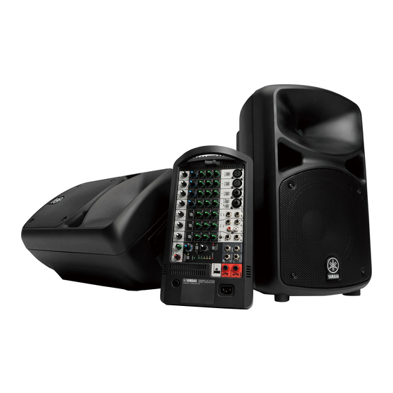
Thank you and congratulations on your purchase of the Yamaha STAGEPAS 600i Portable PA
System. The STAGEPAS 600i is an all-in-one PA system, consisting of two speakers and a
powered mixer. In order to get the most out of your new STAGEPAS 600i and its sophisticated
functions, we suggest you read through this manual thoroughly. Also keep it in a safe place for
future reference.
Main Features
• 600 watts power amplifier for versatility in a wide variety of performance applications.
• 10-inch two-way bass-reflex type speakers for high-quality, powerful sound.
• 10-channel mixer features four mono mic/line and three stereo line input channels to support a wide
range of inputs.
• Yamaha's high-quality SPX reverb, providing optimum processing for instruments or vocals.
• Feedback Suppressor, which automatically cuts and prevents undesirable feedback noise.
• USB connector for convenient digital connection with an iPod/iPhone, and allows charging of the device.
• Independent three-band equalizer on each channel for tonal adjustment and sound control.
Quick Start Guide
Connecting the speakers and the mixer
1
Slide the mixer's lock in the direction of the arrow (shown below), and
then remove it from the speaker.
2
Open the cover panel attached to the other speaker, and then remove
the box from inside the accessory compartment.
Two speaker cables and one power cord are included in the box.
Accessory
compartment
Cover panel
NOTE
After the box is removed, loose items, such as the included power cord, speaker cables, owner's
manual (this booklet), and an optional microphone can conveniently be stored in the accessory
compartment.
3
Connect the speakers and the mixer.
Connect the mixer's SPEAKERS jack to the speakers' input jack using the included
speaker cables. As shown in the illustration below, make sure to insert the speaker
cables all the way inside until secure.
Input jack
SPEAKERS jack
Caution
Use only the included speaker cables. Use of other cables may result in heat generation, or short
circuiting.
EN
Connecting microphones, instruments, and audio
devices to the mixer
4
Connect desired devices, such as a microphone, or an instrument to the
input jack of the mixer.
Refer to the illustration on the mixer shown below or the connection example of the cover
panel of the accessory compartment.
Getting sound out of the system
5
Connect the included power cord.
First, connect it to the mixer's AC IN connector, then
to a power outlet.
6
Turn the mixer's LEVEL controls
(white knobs) and MASTER
LEVEL control (red knob) to the
minimum (zero). Also, set the
equalizer controls (green knobs)
to the center "D" or "MUSIC"
position.
7
Set the MIC/LINE switch to the MIC (N)
position for microphone connection, and to
the LINE (O) position for connection of an
instrument or audio device.
8
Turn on the power of the connected sound
source (if applicable), then the mixer.
The POWER LED lights.
9
Set the MASTER LEVEL control to the "D" position.
10
While playing your instrument or singing into the microphone, use the
LEVEL control to adjust the volume of the corresponding channel.
11
Use the MASTER LEVEL control to adjust the overall volume.
If you hear the sound and the volume seems appropriate, setup is complete. If not,
please refer to the check list in the "Troubleshooting" section on the back of this booklet.
NOTE
To avoid any loud, unexpected noise from the speaker, first turn off the power to the mixer, then the
connected sound source (such as an instrument or audio device).
Making optimum volume settings
When the volume is too loud
Turn the LEVEL control to the minimum (zero). Set the MIC/LINE
switch to the LINE (O) position, then slowly raise the LEVEL
control until the desired volume is reached.
When the volume is too soft
Turn the LEVEL control to the minimum (zero). Set the MIC/LINE
switch to the MIC (N) position, then slowly raise the LEVEL control
until the desired volume is reached.
Applying Reverb
The STAGEPAS 600i features a built-in reverb processor that is in the same league as our famed
SPX effect processor series. This reverb lets you simulate the acoustics of different performance
environments, such as concert halls and small clubs, and add warm, natural ambience to your
vocals or instrument performance.
1
Press down the REVERB switch to turn it on.
The LED lights when REVERB is on.
2
Position the REVERB TYPE/TIME control to the desired
reverb type and time (length).
Turning the control toward the right lengthens the time of the selected reverb type.
3
Use the REVERB control to adjust the reverb amount of the corresponding
channel.
If necessary, repeat steps 2 and 3 to determine the optimum reverb setting.
3
Mixer Controls and Functions
Mic/Line input jacks (channels 1-4)
1
Connect microphones, guitars, electronic musical instruments or audio equipment. Channels 3
and 4 provide combo jacks that support both XLR and phone plugs.
Equalizer
MIC/LINE switches (channels 1-4)
2
For low-level signals (including microphones), set the switch to the MIC (N) position. For high-level signals (including electronic
instruments and audio equipment), set the switch to the LINE (O) position.
Hi-Z switch (channel 4)
3
This switch is used when connecting a device directly to the mixer without a DI (direct box)—for example, instruments with passive
pickups, such as an acoustic-electric guitar or electric bass without battery. This function is effective only for the phone jack input.
Line (stereo) input jacks (channels 5/6, 7/8, 9/10)
4
Connect line-level devices such as electronic instruments, acoustic-electric guitars, CD
players, and portable audio players. These jacks support phone, RCA-pin, and stereo-mini
plugs.
NOTE
For the channel 7/8 input, if both phone and RCA-pin jacks are used at the same time, the phone jack will take priority. For the channel
9/10 input, if both phone and stereo mini jacks are used at the same time, the stereo mini jack will take priority. The signal from the device
connected to another jack will be muted. The music signals from iPod/iPhone (9) are always mixed to channels 9/10.
Equalizer controls (HIGH, MID, LOW)
@
This three-band equalizer adjusts the channel's high, mid, and
low frequency bands. Setting the control to the "D" position
produces a flat response in the corresponding band. Turning the
control clockwise boosts the selected band. If you start getting
feedback, turn the control back slightly.
REVERB switch/LED
#
When this switch is on, the LED lights indicating that you can
apply reverb. This switch is off when you turn on the mixer. (Unlike
other switches, this switch cannot be locked.)
$
REVERB TYPE/TIME control
Determines the reverb type and its length. Turning the control
toward the right lengthens the time of the selected reverb type.
HALL: Simulated reverb of a large space, such as a concert
hall.
PLATE: Simulated metal plate reverb, producing a more hard-
edged and bright sound.
ROOM: Simulated acoustic ambience of a small room.
ECHO: Echo effect suitable for vocals.
REVERB controls (channels 1-4)
%
Determines the amount of reverb for each channel when the
REVERB switch (#) is on.
ST/MONO switches (channels 5/6, 7/8, 9/10)
^
Setting the switch to ST (STEREO) (N) will assign the signals from the L and R channels to
each left and right speaker and output each signal. Setting the switch to MONO (O) will mix
the output of different L and R sources to output the same signal to both the left and right
speakers. For keyboards with mono output, guitars, or other non-stereo sound sources,
when the switch is set to MONO, the stereo jacks can be conveniently used as multiple
mono jacks.
LEVEL meter
&
The LEVEL meter shows the level of output signal from the SPEAKERS L/R jacks.
Caution
If used at a high volume so that the LIMITER LED flashes continuously, the internal power
amplifier section is being excessively overloaded and may malfunction. Reduce the output level
with the MASTER LEVEL control so that the indicator flashes only briefly on the highest transient
peaks.
POWER LED
*
This LED lights when the power is turned on by pressing the power switch.
(
FEEDBACK SUPPRESSOR switch/LED
When this switch is on, the LED lights indicating that feedback is automatically suppressed.
(This utilizes a seven-band notch filter. When this switch or the power switch is off, the notch
filter will be reset.)
5
MONITOR OUT jacks
9
USB connector
These are for connection to a powered
Connect your iPod/iPhone using a USB
speaker for monitoring purposes,
cable to play music and charge the
and output a mix of the signals from
iPod/iPhone. Use the LEVEL control
channels 1 to 9/10. You can adjust the
of channels 9/10 to adjust the volume,
output level using the MONITOR OUT
since the music signals are mixed
control (!). If only the L (MONO) jack
to those channels. This connector
is used, the signals from the L and R
supplies 5V power to the connected
channels are mixed and output.
USB device. This connector does not
support digital playback from USB
Long
SUBWOOFER OUT jack
6|
devices other than the iPod/iPhone.
This is for connection to a powered
For playback of such devices, use
subwoofer, and outputs a mono
appropriate stereo mini or RCA pin
Short
signal. If this jack is in use, the low
connectors.
frequencies below 120Hz to the
SPEAKERS L/R jacks will be cut. The
output level is linked to that of the
• Use a genuine Apple Dock Connector
MASTER LEVEL control (C).
• Please do not use a USB hub.
7
REVERB FOOT SW jack
1
NOTE
This is for connection to an unlatched-
type footswitch such as the Yamaha
FC5—useful for solo performers, since
2
you can toggle the reverb on and off
as needed with your foot.
SPEAKERS L/R jacks
8
Use the included speaker cables to
connect the speakers.
PHANTOM (CH1/2) switch /LED
)
When this switch is on, the LED lights indicating that phantom
power is available for channels 1 and 2. Turn this switch on to
supply power to condenser microphones or a DI (direct box).
Caution
XLR
phone
Follow the important precautions below, in order to prevent
noise and possible damage to external devices and the unit
when you operate this switch.
• Be sure to leave this switch off if you do not need phantom
power, or when you connect a device that does not support
phantom power to channels 1 or 2.
• Do not connect/disconnect a cable to/from channels 1 and 2
while this switch on.
• Turn the LEVEL control of the channels 1 and 2 to the
minimum before operating this switch.
RCA-pin
stereo-mini
MONITOR OUT control
!
Determines the signal level output from the MONITOR OUT
jacks (5). The MASTER LEVEL control does not affect the
MONITOR OUT signal.
5
1
4
3
2
)
&
!
@
#
$
^
%
D
A
B
A
LEVEL controls
Use these controls to adjust the volume for each channel. To reduce noise, set any LEVEL controls on
unused channels to the minimum.
B
MASTER EQ (equalizer) control
Use this control to adjust the overall sound frequency balance. The center position "MUSIC" is a basic
setting and if you turn the control counterclockwise, this creates an optimum setting for speech, cutting
unneeded low range frequencies. If you turn the control clockwise, it creates an optimum setting for
playback of sound sources, since the low range is boosted. If you turn the control clockwise further, the
LED lights indicating that the bass boost function turns on, giving you even more powerful bass tone.
MASTER LEVEL control
C
Determines the volume of the signal output from the SPEAKERS L/R jacks. This allows you to adjust the
overall volume without changing the relative volume balance among the various channels.
D
Vents
F
(power) switch
These are the vents for the cooling fan
For turning the power of the mixer on (O) and off (N).
inside the mixer. Do not block the vents
Caution
when in use.
Rapidly turning the unit on and off in succession may
AC IN jack
cause it to malfunction. After turning the unit off, wait for
E
about 5 seconds before turning it on again.
Connect the included power cord here.
Caution
USB Cable for the iPod/iPhone
connection.
If you connect an iPhone,
incoming calls or emails may
cause a notification sound to be
output. In order to prevent this, we
recommend setting the iPhone's
Airplane mode to "on."
6
8
7
E
9
*
(
D
F
C
Advertisement

Related Manuals for Yamaha STAGEPAS 600i


Summary of Contents for Yamaha STAGEPAS 600i
- Page 1 These are for connection to a powered Connect your iPod/iPhone using a USB PORTABLE PA SYSTEM The STAGEPAS 600i features a built-in reverb processor that is in the same league as our famed speaker for monitoring purposes, cable to play music and charge the and output a mix of the signals from iPod/iPhone.
- Page 2 0 dBu=0.775 Vrms, 0 dBV=1 Vrms Phone*: Unbalanced when the speaker is handling program material with heavy bass it may take some time to be recognized by Specifications and descriptions in this owner’s manual are for information purposes only. Yamaha Corp.reserves the right to „ Handling and Maintenance … content.
Need help?
Do you have a question about the STAGEPAS 600i and is the answer not in the manual?
Questions and answers