
Subscribe to Our Youtube Channel
Summary of Contents for Sit PROFLAME GT
- Page 1 PROFLAME GT SYSTEM USE AND INSTALLATION INSTRUCTIONS Read the instructions before use. This control must be installed in accordance with the rules in force.
- Page 2 English The Proflame GT is a modular remote control system that directs the functions of a hearth appliance. The Proflame GT is configured to control the ON/OFF operation of the main burner and provides thermostatic control of the hearth appliance.l...
-
Page 3: Technical Data
TECHNICAL DATA Remote Control Supply voltage 4.5 V (three 1.5 V AAA batteries) Ambient temperature ratings 0 - 50 °C (32 - 122 °F) Radio frequency 315 MHz Receiver Supply voltage 6.0 V (four 1.5 V AA batteries) Ambient temperature ratings 0 - 60 °C (32 - 140 °F) Radio frequency 315 MHz... -
Page 4: System Description
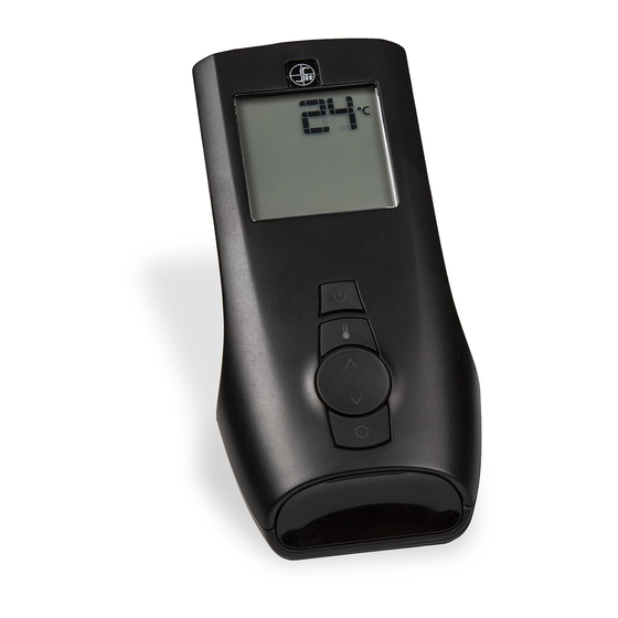
SYSTEM DESCRIPTION The Proflame remote Control System consists of two elements: 1. Proflame Transmitter 2. Proflame Receiver and wiring harness to connect the Receiver to the gas valve. The PROFLAME System complements any 820 NOVA millivolt Combination Gas Control. TRANSMITTER (Remote Control with LCD Display) The Proflame Transmitter uses a streamline design with a simple button layout and informative LCD Display (Fig. -
Page 5: Installation
RECEIVER The Proflame Receiver (Fig. 3) connects directly to the gas valve with the wiring harness provided. The Receiver is powered by 4 AA type batteries. The Receiver accepts commands via radio frequency from the Transmitter to operate the appliance in accordance with the particular Proflame system configuration. -
Page 6: Operating Procedure
Connecting to the Gas Valve The wiring harness for the Proflame GT system has two wires labeled “TP” & “TPTH”. Connect the wires to the gas valve as labeled. (TH to TH and TPTH to TPTH) (Fig. 5) REMOTE REMOTE... - Page 7 Temperature indication Display With the Transmitter in the “OFF” position, press the Thermostat Key and the Mode Key at the same time. Look at the LCD screen on the Transmitter to verify that a C or F is visible to the right of the Room Temperature display.
-
Page 8: Room Temperature
REMOTE ON/OFF FLAME CONTROL With the system on, and the flame present in the appliance, pressing the Down Arrow Key will turn off while the remote system is still on. If the Up Urrow Key is pressed while in the above described state the flame will come on. -
Page 9: Low Battery Power Detection
KEY LOCK This function will lock the keys to avoid unsupervised operation. To activate this function, press the MODE and UP Arrow Keys at the same time (Fig. 18). To de- activate this function, press the MODE and UP Arrow Keys at the same time. - Page 10 WARNING Fire Hazard. Can cause severe injury or death The Receiver causes ignition of the appliance. The appliance can turn on suddenly. Keep away from the appliance burner when operating the remote system or activating manual bypass of the remote system.. CAUTION Property Damage Hazard.
-
Page 12: Dimensional Drawings
DIMENSIONAL DRAWINGS PROFLAME Transmitter REMOTE Wall mounted REMOTE Hearth mounted PROFLAME Receiver Dimensions are in millimeters...
Need help?
Do you have a question about the PROFLAME GT and is the answer not in the manual?
Questions and answers
I have a wall mounted SIT Proflame Transmitter (GT) 0.584.046. What replacement transmitter can I use to replace that transmitter? Can any SIT Proflame Transmitters be used interchangeable with the 0.584.046?