Table of Contents
Advertisement
Instruction Manual
PLEASE READ THIS ENTIRE MANUAL CAREFULLY BEFORE PROCEEDING WITH THE
CONSTRUCTION OF YOUR AIRPLANE
Model Aircraft Manufacturing
P.O. Box 788
Urbana, IL61801
(217)398-8970
FAX (217) 398-7721
Warning!
This R/C kit and the model you will build is not a toy! It is
capable of serious bodily harm and property damage. It is
your responsibility and yours alone to build this kit
correctly, properly install all R/C components and flying
gear (engine, tank, pushrods, etc...) and to test the model
and fly it only with experienced, competent help in
accordance with all safety standards and common sense
Academy of Model Aeronautics
as set down in the Academy of Model Aeronautics Safety
5151 East Memorial Drive
Code. It is suggested that you join the AMA and become
Muncie, IN 47302
properly insured before you attempt to fly this model. If you
(800) 435-9262
are just starting R/C modeling, consult your local hobby
FAX (765) 741-0057
shop or write to the Academy of Model Aeronautics to find
and experienced instructor in your area.
ENTIRE CONTENTS © COPYRIGHT 2000
COLT4P02V1.1 for USAA2070
Advertisement
Table of Contents

Related Manuals for U.S. Aircore Colt 40 SLT

Summary of Contents for U.S. Aircore Colt 40 SLT
-
Page 1: Instruction Manual
Instruction Manual PLEASE READ THIS ENTIRE MANUAL CAREFULLY BEFORE PROCEEDING WITH THE CONSTRUCTION OF YOUR AIRPLANE Model Aircraft Manufacturing P.O. Box 788 Urbana, IL61801 (217)398-8970 FAX (217) 398-7721 Warning! This R/C kit and the model you will build is not a toy! It is capable of serious bodily harm and property damage. -
Page 2: Required Items
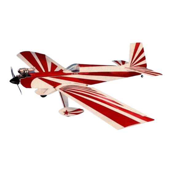
INTRODUCTION Congratulations and thank you for purchasing the U.S. Aircore Colt 40 SLT.This model is designed to be one of the most durable R/C aircraft on the market. The unique building material uses super tough corrugated plastic that will not break. - Page 3 Building Sequence If this is your first AirCore plane, we recommend you build the COLT 40 over a period of 3-4 evenings or a couple of days. Your future AirCore planes will take less time, but we feel it's important to take your time on this first one and do it right. The first evening we will prepare a few parts with glue and epoxy, and get to know the plane.
- Page 4 1.3 Using epoxy, glue the two 1/8" die-cut plywood cartridge halves together. Assemble and fuelproof the PC. Glue and clamp the reinforcing doublers on the top and bottom of the engine mount area. Be sure to line up the inside cavity edges of the PC with the doublers while GLUE &...
- Page 5 1.6 Locate the 8 oz. tank and assemble it. The PC is designed to fit snugly around this particular tank with the vent bubble at the top of the tank. Proper tank assembly is important to insure good fuel delivery to your engine in flight. Have your hobby dealer or an experienced modeler check your tank assembly and test it for good "clunk"...
- Page 6 EVENING TWO Tonight we build the fuselage. 2.1 Locate the main fuselage doubters and mark left and right sides (They are marked "L" & "R" with impressions in the AirCore). Lay your fuselage down on a good, flat work surface with the top down and trial fit these to the inside of the fuse.
- Page 7 BULKHEADS CONTROL RODS SHOULD BE CLOSEST TO BOTTOM OF FUSELAGE THREADED END OF CONTROL RODS AT REAR OF FUSELAGE FIGURE7 - PLACEMENT OF BULKHEADS AND CONTROL RODS 2.3 Locate the 6-mil Wing Saddles and trial fit them to the wing saddle area on both sides of the fuselage. Align the punched out holes and the wing saddle itself.
- Page 8 2.9 Insert (trial fit) the 5" long 1/4" Wing Dowels in the prepunched holes. Drill out holes with a 1/4" bit if necessary. Remove the dowels and fuel proof them as you did the PC, with thinned epoxy, and reinstall when dry. Glue the back dowel in place with epoxy or clear adhesive/sealant.
- Page 9 2.14 Using the two 12" long 3/16" dowels supplied, join the two stabilizer halves together by pushing the dowels up into "flutes" of the stab as shown in the illustration. The middle of the dowels should be at the center of the stab assembly when complete.
-
Page 10: Fin And Rudder
2.17 Install the elevator control horn. Locate the angled elevator control horn white plastic stiffeners and glue them to the VIEW top and bottom of the right elevator using contact cement. The rough sides glue against the elevator surfaces - the smooth sides are exposed. - Page 11 FINAL ASSEMBLY OF THE FUSELAGE STAB TIPS SHOULD BE LINE UP EQUIDISTANT FROM NOSE SLOTS OF FUSELAGE REAR OF STAB SHOULD BE EVEN WITH THE REAR OF THE FUSELAGE FIGURE 13- MOUNTING THE STABILIZER 2.21 Prepare stab. Position the stab on the fuse top over the slot for the fin. LINE UP THE TRAILING EDGE OF THE STAB WITH THE REAR OF THE FUSELAGE.
- Page 12 INSTALL TRIM STRIPS ON USE CLEAR ADHESIVE/SEALANT LEADING EDGES OF BOTH TO SEAL JOINTS BETWEEN THE FIN AND STAB TO COVER FIN AND STAB, FIN AND FUSE AND FLUTES EXPOSED TO AIR FLOW STAB AND FUSE BOTTOM OF FIN SHOULD BE FLUSH WITH TOP OF STAB FIGURE 14 - MOUNTING THE VERTICAL FIN 2.25 Locate the plastic edge trim for the tail section and cut it to fit the leading edges of the stab and fin.
- Page 13 EVENING THREE Tonight we will assemble the wing. You should already have built the spar on evening one. If not, go back to section one and build the spar. ASSEMBLY OF THE WING IS THE MOST IMPORTANT PART OF BUILDING THE PLANE AND SHOULD BE DONE ON A GOOD, FLAT WORKING SURFACE.
-
Page 14: Building The Wing
BUILDING THE WING To build the wing, we build and install the ailerons, fold up the wing halves around the spar, install torque rods and install a wing "wrap." AILERONS 3.06 First lay out the wings on a flat work surface and position them so that the inside is facing you and the wing bottoms (square tips) are nearest you. - Page 15 4-MIL SPAR ALIGNMENT STRIPS INSTALLED ALONG LINES DRA WN WITH PEN RIGHT WING TOP INSIDE BETWEEN ALIGNMENT HOLES 3.11 Using contact cement, carefully position the hinges and glue completed aileron assemblies to the trailing edges of each wing. Glue the aileron assemblies to the inside bottom of the wings.
- Page 16 FRONT RIB ASSEMBLY REAR RIB ASSEMBLY CROSS SECTION DRAW LINES WITH PEN CONNECTING RIB ALIGNMENT INDENTS IN WING AND GLUE RIBS BETWEEN LINES NEXT GLUE 6-MIL LANDING GEAR REINFORCEMENT PIECES TO BOTTOM OF WING BETWEEN RIBS RIGHT WING INSIDE BOTTOM LEFT WING INSIDE BOTTOM 6-MIL L.G.
- Page 17 3.21 When satisfied, fold the wing back out and coat the trailing edges of the wing top and bottom and the top of the hinge strip with contact cement. Also apply contact cement to the top of the spar and the top of the wing between the alignment strips.
-
Page 18: Landing Gear
INSTALL THE WING WRAP 3.27 Locate the 6" wide 2-mil wing wrap and mark its location on the wing by drawing two lines around the wing, each 3" from the center. If your wing is premarked, the wing wrap should extend about 1/16" outside each mark, just covering it 3.28 Cut a slot in the wing wrap to allow it to wrap around the wing with the torque rods extending up through the slot. -
Page 19: Wheel Pants
and trim away enough of the excess on each side of the slit to allow you to push the landing gear wire up inside the flute. At the gear exit point on each end, there should be two flutes forward of the flute selected for the gear and three flutes aft of the gear flute. - Page 20 CHECK FOR WARP - FIX IF NECESSARY. GOOD WING • BOTH TIPS ARE IDENTICAL A 7 TRAILING EDGE WITH SAME AMOUNT OF WASH-OUT AT TIPS TRAILING EDGE UP TOO HIGH AT TIP FIGURE 33 - IDENTIFYING WARP VIEW FROM TRAILING EDGE Now is the time to see if you have built a straight wing.
- Page 21 EVENING FOUR Tonight we will assemble the Power Cartridge and perform final assembly on your plane. IF THIS IS YOUR FIRST R/C AIRPLANE, PLEASE HAVE A HOBBY DEALER OR VERY EXPERIENCED R/C MODELER CHECK YOUR PC ASSEMBLY PRIOR TO ATTEMPTING TO FLY YOUR PLANE. Power Cartridge 4.01 Install servos.
-
Page 22: Nose Gear & Steering
4.06 Install your on/off switch either on the fuselage or on the PC between the radio and the flex tank. If you install the on/off switch in the fuselage, place it below the rails where it will not interfere with the PC sliding in and out of the fuse, and where the connectors will be accessible for connection to the radio and battery when you install the PC. - Page 23 4.12 Install the 27" long steel push rods for the rudder and elevators. The rods should have been installed along with the bulkheads when building the fuselage. If they were not, "fish" them through the holes in the bulkheads at this time, starting at the rear of the plane.
-
Page 24: Troubleshooting
Checking Wing Incidence 4.15 The wing bottom is relatively flat at the root. When mounted the wing bottom should be in alignment with the angle of the fuselage top, and therefore also with the incidence of the stab. This 0 degrees incidence is important in the proper flight characteristics of your plane. - Page 25 CROSS SECTION SLIT HINGE FREE WITH HOBBY KNIFE The modeler's fix is to apply a 1" long bead of clear adhesive/sealant (silicone) into the aileron hinge flute, beginning about 1" inboard of the wing tip end of each aileron. LEFT WING Wait for the sealant to cure (overnight) and use a hobby knife APPLY BEAD OF BOTTOM...
-
Page 26: Repair Tips
REPAIR TIPS Most AirCore planes will survive the worst mishaps. If there is damage, it is normally restored with a little patience and repair time. We've found that repairing is normally preferable to building a completely new plane! DON'T THROW AWAY YOUR SCRAP AIRCORE!!! We've found that AirCore tends to bend or occasionally tear in a severe impact, but that it is repairable most of the time. - Page 27 So how do you learn to fly? Your local full-service hobby dealer should be able to guide you to a local model airplane club and flying field where help will be available. Your hobby dealer also stocks books and sometimes video tapes on learning how to fly. PUT YOURSELF THROUGH GROUND SCHOOL with these aids and learn what you're doing before you go to the field.
- Page 28 PARTS LIST FOR COLT 40 SLT NAME QTY Description AC40S02 ELEVATOR&RUDDER STIFFENERS AC40W07 ALIGNMENT STRIPS (8) AC40W08 HINGE Strips/Fuse BULKHEADS CANPY072 CANOPY COLT4A03 Power Cartridge COLT4F02 SADDLE DOUBLERS/Rib/Lg Brace COLT4F03 FUSE/Ail/Turtle deck/Lg Cover COLT4FOI FUSE/Raildblrs/Wing wrap COLT4P02 Instruction manual COLT4SOI...
Need help?
Do you have a question about the Colt 40 SLT and is the answer not in the manual?
Questions and answers