Table of Contents
Advertisement
Quick Links
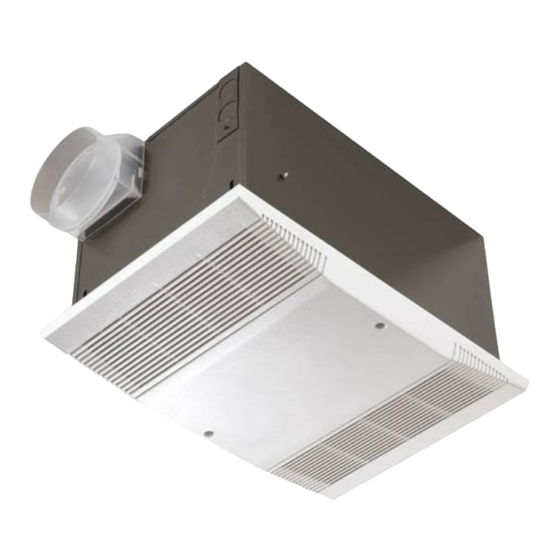
Heat-A-Vent
Combination
MODEL: 9905-RO2
FOR BEST RESULTS
In a new construction site, install the housing (complete
with heater and ventilator) during rough-in construction of
the building. The grille should be installed when the finished
ceiling is in place.
Installation in an existing, finished building requires
an accessible area (attic or crawl space) above the
planned location. See "INSTALLATION IN EXISTING
CONSTRUCTION."
Do not install closer than 12 inches to a vertical surface.
Do not install over tub or shower enclosure.
• F or installation in sloped ceilings up to 12/12 pitch.
• Ductwork must point up.
UNIT DIMENSIONS
Refer to Figure 1 for housing's dimensions.
NOTE: If there will be a finished second floor above,
the Model 9905 housing requires a minimum of 2" x 8"
joist construction for mounting.
WIRING AND DUCTWORK
1. R un the required wiring during rough-in stage of construction.
2. T otal connected load: 1630 watts.
3. P lan to run 120vAC, 60 Hz wiring (with ground) on a
separate 20 Amp circuit from a power source, through
the provided wall switch, to the housing's junction box.
See wiring diagram.
4. U se 4" round duct.
INSTALLATION IN
NEW CONSTRUCTION
PREPARATION
1. L oosen hanger bar brackets to allow bars to be inserted.
2. R efer to Figure 2. Insert hanger bars into brackets.
3. R efer to Figure 3. Slide hanger bar brackets down to end
of slot closest to outside edge of housing. Tighten brackets
in this position.
4. R efer to Figure 4. Remove junction box cover by
removing one screw.
5. R efer to Figure 4. Remove appropriate wiring knockout(s)
and install approved box connector(s).
®
INSTALLATION INSTRUCTIONS
READ & SAVE THESE INSTRUCTIONS!
ADJUSTMENT
SLOT
FIGURE 3
9
3
⁄
"
4
7
3
⁄
"
4
14"
FIGURE 1
HANGER BARS
FIGURE 2
VENT
JUNCTION
BOX
COVER
HEAT
KNOCKOUTS
FIGURE 4
Advertisement
Table of Contents

Related Manuals for NuTone 9905-RO2


Summary of Contents for NuTone 9905-RO2
-
Page 1: Installation Instructions
INSTALLATION INSTRUCTIONS READ & SAVE THESE INSTRUCTIONS! Heat-A-Vent ® ⁄ ” Combination MODEL: 9905-RO2 ⁄ ” FOR BEST RESULTS In a new construction site, install the housing (complete with heater and ventilator) during rough-in construction of the building. The grille should be installed when the finished ceiling is in place. 14” Installation in an existing, finished building requires an accessible area (attic or crawl space) above the planned location. See “INSTALLATION IN EXISTING FIGURE 1 CONSTRUCTION.” Do not install closer than 12 inches to a vertical surface. Do not install over tub or shower enclosure. • F or installation in sloped ceilings up to 12/12 pitch. - Page 2 MOUNTING THE HOUSING 1. Locate housing between joists. DUCT COLLAR 2. R efer to Figure 5. Using nails, secure hanger bars to joists. NOTE: The hanger bar brackets are adjustable. Allowing for the thickness of the finished ceiling, mount hanger bars so that edge of housing will be flush with the finished ceiling. 3. ...
- Page 3 ” wide. Make cutout FIGURE 7 in ceiling. 3. F ollow steps under “PREPARATION” page 1. 4. F rom above, lower housing into the cutout and secure hanger brackets. Install duct collar, connect duct, and run wiring through box connectors. 5. F rom below, adjust housing so that it is flush with the finished ceiling. 6. F rom below, make wiring connections as shown in figure 7. R eplace junction box cover. 8. I nsert heater and ventilator plugs into proper receptacles. ⁄ ” 9. I nstall grille. NOTE: This heater is provided with a Self-Hold resetable thermal protector. If the heater shuts off during operation, turn to off at the wall switch and wait approximately 15 minutes before turning back on. If heater does not reset or trips repeatedly, contact a NuTone service center. ⁄ ” FIGURE 8...
- Page 4 One Year Limited Warranty WARRANTY OWNER: Broan-NuTone warrants to the original consumer purchaser of its products that such products will be free from defects in materials or workmanship for a period of one (1) year from the date of original purchase. THERE ARE NO OTHER WARRANTIES, EXPRESS OR IMPLIED, INCLUDING, BUT NOT LIMITED TO, IMPLIED WARRANTIES OF MERCHANTABILITY OR FITNESS FOR A PARTICULAR PURPOSE. During this one year period, Broan-NuTone will, at its option, repair or replace, without charge, any product or part which is found to be defective under normal use and service. THIS WARRANTY DOES NOT EXTEND TO FLUORESCENT LAMP STARTERS OR TUBES, FILTERS, DUCT, ROOF CAPS, WALL CAPS AND OTHER ACCESSORIES FOR DUCTING. This warranty does not cover (a) normal maintenance and service or (b) any products or parts which have been subject to misuse, negligence, accident, improper maintenance or repair (other than by Broan-NuTone), faulty installation or installation contrary to recommended installation instructions. The duration of any implied warranty is limited to the one year period as specified for the express warranty. Some states do not allow limitation on how long an implied warranty lasts, so the above limitation may not apply to you. Broan-NuTone’S OBLIGATION TO REPAIR OR REPLACE, AT Broan-NuTone’S OPTION, SHALL BE THE PURCHASER’S SOLE AND EXCLUSIVE REMEDY UNDER THIS WARRANTY. Broan-NuTone SHALL NOT BE LIABLE FOR INCIDENTAL, CONSEQUENTIAL OR SPECIAL DAMAGES ARISING OUT OF OR IN CONNECTION WITH PRODUCT USE OR PER- FORMANCE. Some states do not allow the exclusion or limitation of incidental or consequential damages, so the above limitation or exclusion may not apply to you. This warranty gives you specific legal rights, and you may also have other rights, which vary from state to state. This warranty supersedes all prior warranties.
Need help?
Do you have a question about the 9905-RO2 and is the answer not in the manual?
Questions and answers