Table of Contents
Advertisement
Advertisement
Table of Contents

Summary of Contents for Lever HOMIV 1KVA-5KVA
- Page 1 User Manual HOMIV 1KVA-5KVA INVERTER / CHARGER...
-
Page 2: Table Of Contents
Table Of Contents ABOUT THIS MANUAL ..........................1 Purpose ..............................1 Scope ................................ 1 SAFETY INSTRUCTIONS ..........................1 INTRODUCTION............................2 Features..............................2 Basic System Architecture .......................... 2 Product Overview ............................3 INSTALLATION ............................. 4 Unpacking and Inspection .......................... 4 Preparation ..............................4 Mounting the Unit ............................ -
Page 3: About This Manual
ABOUT THIS MANUAL Purpose This manual describes the assembly, installation, operation and troubleshooting of this unit. Please read this manual carefully before installations and operations. Keep this manual for future reference. Scope This manual provides safety and installation guidelines as well as information on tools and wiring. SAFETY INSTRUCTIONS WARNING: This chapter contains important safety and operating instructions. -
Page 4: Introduction
INTRODUCTION This is a multi-function inverter/charger, combining functions of inverter, solar charger and battery charger to offer uninterruptible power support with portable size. Its comprehensive LCD display offers user-configurable and easy-accessible button operation such as battery charging current, AC/solar charger priority, and acceptable input voltage based on different applications. -
Page 5: Product Overview
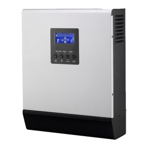
Product Overview 4KVA/5KVA single model 1KVA model 4KVA/5KVA parallel model 1. LCD display 2. Status indicator 3. Charging indicator 4. Fault indicator 5. Function buttons 2KVA/3KVA model 6. Power on/off switch 7. AC input NOTE: For parallel model installation and operation, 8. -
Page 6: Installation
INSTALLATION Unpacking and Inspection Before installation, please inspect the unit. Be sure that nothing inside the package is damaged. You should have received the following items inside of package: Ÿ The unit x 1 Ÿ User manual x 1 Ÿ Communication cable x 1 Ÿ... -
Page 7: Battery Connection
Install the unit by screwing three screws. Battery Connection CAUTION: For safety operation and regulation compliance, it’s requested to install a separate DC over-current protector or disconnect device between battery and inverter. It may not be requested to have a disconnect device in some applications, however, it’s still requested to have over-current protection installed. - Page 8 Please follow below steps to implement battery connection: 1. Assemble battery ring terminal based on recommended battery cable and terminal size. 2. 1KVA model supports 12VDC system, 2KVA/3KVA model supports 24VDC system and 4KVA/5KVA model supports 48VDC system. Connect all battery packs as below chart. It’s suggested to connect at least 100Ah capacity battery for 1-3KVA model and at least 200Ah capacity battery for 4KVA/5KVA model.
-
Page 9: Ac Input/Output Connection
AC Input/Output Connection CAUTION!! Before connecting to AC input power source, please install a separate AC breaker between inverter and AC input power source. This will ensure the inverter can be securely disconnected during maintenance and fully protected from over current of AC input. The recommended spec of AC breaker is 10A for 1KVA, 20A for 2KVA, 32A for 3KVA , 40A for 4KVA and 50A for 5KVA. -
Page 10: Pv Connection (Only Apply For The Model With Solar Charger)
WARNING: Be sure that AC power source is disconnected before attempting to hardwire it to the unit. 4. Then, insert AC output wires according to polarities indicated on terminal block and tighten terminal screws. Be sure to connect PE protective conductor ( ) first. - Page 11 PV Module Selection: WARNING! This inverter is only compatible with PV module types of single crystalline and poly crystalline. When selecting proper PV modules, please be sure to consider below requirements first: 1. Open circuit Voltage (Voc) of PV modules not exceeds max. PV array open circuit voltage of inverter. INVERTER MODEL 1KVA 2KVA...
-
Page 12: Final Assembly
PV module numbers in Parallel: 6 Total PV module numbers: 1 x 6 = 6 Take 4K/5K model inverter as an example to select proper PV module. After considering Voc of PV module not exceed 90Vdc and max. Vmpp of PV module close to 60Vdc or within 56Vdc ~ 72Vdc, we can choose PV module with below specification. -
Page 13: Operation
Communication Connection Please use supplied communication cable to connect to inverter and PC. Insert bundled CD into a computer and follow on-screen instruction to install the monitoring software. For the detailed software operation, please check user manual of software inside of CD. OPERATION Power ON/OFF Once the unit has been properly installed and the batteries are connected well, simply press On/Off switch... -
Page 14: Lcd Display Icons
Function Keys Function Key Description To exit setting mode To go to previous selection DOWN To go to next selection ENTER To confirm the selection in setting mode or enter setting mode LCD Display Icons Icon Function description Input Source Information Indicates the AC input. - Page 15 In AC mode, it will present battery charging status. Status Battery voltage LCD Display <2V/cell 4 bars will flash in turns. Bottom bar will be on and the other three Constant 2 ~ 2.083V/cell bars will flash in turns. Current mode / Bottom two bars will be on and the other 2.083 ~ 2.167V/cell Constant...
-
Page 16: Lcd Setting
Mode Operation Information Indicates unit connects to the mains. Indicates unit connects to the PV panel. Indicates load is supplied by utility power. Indicates the utility charger circuit is working. Indicates the DC/AC inverter circuit is working. Mute Operation Indicates unit alarm is disabled. LCD Setting After pressing and holding ENTER button for 3 seconds, the unit will enter setting mode. - Page 17 Solar energy provides power to the loads as first priority. If solar energy is not sufficient to power all connected loads, battery SBU priority energy will supply power to the loads at the same time. Utility provides power to the loads only when battery voltage drops to either low-level warning voltage or the setting point in program 12.
- Page 18 Restart disable Restart enable (default) Auto restart when over temperature occurs 50Hz (default) 60Hz Output frequency Available options in 1K model: 20A (default) Maximum utility charging Available options in 2K/3K model: current 30A (default) Note: If setting value in program 02 is smaller than that in program in 11, the Available options in 4K/5K model: inverter will apply charging...
- Page 19 23.0V (default) 23.5V 24.0V 24.5V 25.0V 25.5V Available options in 4K/5K model: 46V (default) If this inverter/charger is working in Line, Standby or Fault mode, charger source can be programmed as below: Solar first Solar energy will charge battery as first priority.
- Page 20 Only Solar Solar energy will be the only charger source no matter utility is available or not. If this inverter/charger is working in Battery mode or Power saving mode, only solar energy can charge battery. Solar energy will charge battery if it's available and sufficient. Alarm on (default) Alarm off Alarm control...
-
Page 21: Display Setting
Floating charging voltage (only available in 4K/5K If self-defined is selected in program 5, this program can be model) set up. Setting range is from 48.0V to 58.4V and increment of each click is 0.1V. If self-defined is selected in program 5, this program can be set up. - Page 22 PV voltage=60V, Load percent=70% PV voltage/Load percentage Current ≧ 10A Charging current/Output voltage Current < 10A When connected load is lower than 1kVA, load in VA will present xxxVA like below chart. Input voltage/Load in VA When load is larger than 1kVA (≧1KVA), load in VA will present x.xkVA like below chart.
- Page 23 When load is lower than 1kW, load in W will present xxxW like below chart. Input voltage/Load in Watt When load is larger than 1kW (≧1KW), load in W will present x.xkW like below chart. Main CPU version 00014.04 Main CPU version checking Secondary CPU version 00003.03 Secondary CPU version checking...
-
Page 24: Operating Mode Description
Operating Mode Description Operation mode Description LCD display Charging by utility and PV energy. Standby mode / Power saving mode Charging by utility. Note: *Standby mode: The inverter is No output is supplied by the not turned on yet but at this unit but it still can charge time, the inverter can charge batteries. - Page 25 Charging by utility and PV energy. (Only available in 1K/2K/3K model) Charging by utility. (Only available in 1K/2K/3K model) Fault mode PV energy and utility can Note: charge batteries. *Fault mode: Errors are caused by inside circuit error or external Charging by PV energy.
-
Page 26: Fault Reference Code
Power from battery and PV energy. The unit will provide output Battery Mode power from battery and PV power. Power from battery only. Fault Reference Code Fault Code Fault Event Icon on Fan is locked when inverter is off. Over temperature Battery voltage is too high Battery voltage is too low Output short circuited or over temperature is detected... -
Page 27: Warning Indicator
Warning Indicator Warning Warning Event Audible Alarm Icon flashing Code Fan is locked when Beep three times every inverter is on. second Battery is over-charged Beep once every second Low battery Beep once every second Overload Beep once every 0.5 second Output power derating Beep twice every 3 seconds... -
Page 28: Specifications
SPECIFICATIONS Table 1 Line Mode Specifications INVERTER MODEL 1KVA 2KVA 3KVA 4KVA 5KVA Input Voltage Waveform Sinusoidal (utility or generator) Nominal Input Voltage 230Vac 170Vac±7V (UPS); Low Loss Voltage 90Vac±7V (Appliances) 180Vac±7V (UPS); Low Loss Return Voltage 100Vac±7V (Appliances) High Loss Voltage 280Vac±7V High Loss Return Voltage 270Vac±7V... -
Page 29: Table 2 Inverter Mode Specifications
Table 2 Inverter Mode Specifications INVERTER MODEL 1KVA 2KVA 3KVA 4KVA 5KVA 1.0/0.8 2.0/1.6 3.0/2.4 4.0/3.2 5.0/4.0 Rated Output Power KVA/KW Pure Sine Wave Output Voltage Waveform 230Vac±5% Output Voltage Regulation 50Hz Output Frequency Peak Efficiency Overload Protection 5s@≥150% load; 10s@110%~150% load 2* rated power for 5 seconds Surge Capacity Nominal DC Input Voltage... -
Page 30: Table 3 Charge Mode Specifications
Table 3 Charge Mode Specifications INVERTER MODEL 1KVA 2KVA 3KVA 4KVA 5KVA Charging Algorithm 3-Step Utility Charging Mode AC Charging Current 10/20Amp 20/30Amp (@V =230Vac) Flooded Battery 14.6 29.2 58.4 Bulk Charging AGM / Gel Voltage 14.1 28.2 56.4 Battery Floating Charging Voltage 13.5Vdc 27Vdc... -
Page 31: Trouble Shooting
TROUBLE SHOOTING Problem LCD/LED/Buzzer Explanation / Possible cause What to do Unit shuts down LCD/LEDs and buzzer automatically will be active for 3 The battery voltage is too low 1. Re-charge battery. during startup seconds and then (<1.91V/Cell) 2. Replace battery. process. -
Page 32: Appendix: Approximate Back-Up Time Table
Appendix: Approximate Back-up Time Table Model Load (VA) Backup Time @ 12Vdc 100Ah (min) Backup Time @ 12Vdc 200Ah (min) 1610 1KVA 1000 Model Load (VA) Backup Time @ 24Vdc 100Ah (min) Backup Time @ 24Vdc 200Ah (min) 1610 1000 2KVA 1200 1400... - Page 33 5000 Note: Backup time depends on the quality of the battery, age of battery and type of battery. Specifications of batteries may vary depending on different manufacturers. LEVER SRL Via Del Lavoro, 17 37020 Arbizzano (VR) – Italy Tel. +39 045 6020162 Fax.