Table of Contents
Advertisement
Operating manual
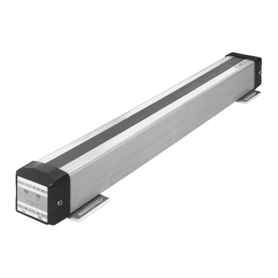
Metal detector ELMETA
®
MDS 50
2
3
4
4
5
6
7
8
8
10
12
13
15
17
18
19
19
21
BEA--250127-EN-09
en
Advertisement
Table of Contents

Summary of Contents for EL elmeta mds 50
-
Page 1: Table Of Contents
Operating manual Metal detector ELMETA ® MDS 50 1. Safety 2. Function 3. Operating device RT 5020/ DO 50.. 3.1 Displays 3.2 Keys 3.3 Basic operation in setup mode 3.4 Setting the metal detector sensitivity 3.5 Instructions for daily use 4. Adapter plate 5. Assembly 6. Installation 7. Commissioning 8. Parameters 9. Error location instructions 10. Maintenance 11. Spare parts 11.1 Exchange of amplifier VK 5020 12. Technical data BEA--250127-EN-09... -
Page 2: Mds
ELMETA ® MDS 50 1. Safety 1.1 Approved applications Metal detector MDA 010. may only be used to scan textiles. Metal detector MDS 50 locates mag n e t ic and non-mag n etic metal particles on moving webs. It is suitable for dry textile materials and non-wovens up to 4 mm thick. The web speed may lie between 3 and 200 meters per minute. Only use the metal detector - when in a technically perfect state - for approved applications - taking into account the safety recommendations and possible dan- gers listed in the operating instructions. Work related to the operation, conversion or setting of the metal detector, its maintenance and repair may be carried out by qualified personnel only. Please observe the ON/OFF switching procedures in the operating instructions. 1.2 Operating manual Look after this operating manual carefully and make sure it is avail- able to personnel at all times. The operating manual is part of the package and should be read carefully prior to mounting, operation and maintenance. 1.3 Safety hints Never touch the edges of moving webs. -
Page 3: Function
ELMETA ® MDS 50 1.6 Operation The web guider should be operated by qualified persons or suitably instructed personnel only. 1.7 Explanation of symbols ➜ = jobs to be performed = important information and instructions = text sections due particular attention to assure the safe op- eration of the metal detector. 2. Function 2.1 Purpose Metal detector MDS 50 locates mag n e t ic and non-mag n etic metal particles on moving webs. It is suitable for dry textile materials and non-wovens up to 4 mm thick. The web speed may lie between 3 and 200 meters per minute. -
Page 4: Operating Device Rt 5020/ Do
ELMETA ® MDS 50 2.3 Operating principle An electro-magnetic alternating field is created in the metal detec- tor probing range. If the web carries a foreign metal particle over the probe, the alternating field is disturbed and signal output 1 set. At the same time, the alarm displays on the sides go on, as does alarm dis- play 1 on the operating panel. Signal output 1 may be used to stop the processing machine or to trigger an optical or acoustic alarm. Depending on the metal detector configuration, the signal output may be reset automatically or manu- ally. Signal output 2 is used for the speed-synchronized triggering on fol- low-up machine devices such as calander rollers, shearing tools or marking systems. The signal output is set and reset depending on the web speed and the distance between the metal detector and fol- low-up machine devices. 3. Operating device RT 5020/ DO 50.. 3.1 Displays 2 1/2-place digital display In normal operation, the digital display indicates the metal detector sensitvity, see l.h. illustration. In setup mode, it indicates either the device address, the parameter number or parameter value, see example 1. Given a permissible value from 200 upwards the "unit digit" is shifted to the right and no longer displayed. This action is indicat- ed by the flashing of the final decimal point, see example 2 and 3. -
Page 5: Keys
ELMETA ® MDS 50 Operating voltage display +5 V DC The display goes on when voltage is supplied to the control electron- ics. Alarm displays 1 and 2 The displays indicate the switching status of the signal outputs: - display 1 goes on when signal output 1 is set. - display 2 flashes as soon as output 1 is set and remains illumi- nated when signal output 2 is set (only when signal output 2 is configured). Both displays flash during system adjustment. LED illuminated bar green yellow red The LED illuminated bar indicates the signal level. In normal opera- tion, one or several green LEDs are always illuminated. If the web moves a foreign metal object across the probe, the yellow and red LEDs go on. The larger the size of the metal particle, the greater the Metal particle signal number of LEDs that light up. The maximum signal value is temporarily stored so that even fast signals may be stored, i.e. once the metal particle has passed over, the LED that had indicated the maximum value, remains illuminated. Then the LEDs to the left go on one after the other until only the Signal maximum value green LEDs are illuminated. All LEDs light up (approx. 60 sec.) during a system adjustment. Once LED illuminated bar this has been completed successfully, only one or several green... -
Page 6: Basic Operation In Setup Mode
ELMETA ® MDS 50 3.3 Basic operation in setup In setup mode, the parameters of E+L CAN devices may be dis- mode played and to a certain extent changed as well. Setup or expand- ed setup mode is accessed with the help of an E+L command device DO ..or operating panel RT ..Para- Para - meter meter value Start setup mode: first press the setup key and then additionally the increase value key. The Start setup mode green LED on the setup key flashes. Enter device number: Press and hold down the setup key and select parameter 0 via the increase value key. Let the setup key go again and enter Enter device number the device number using either the increase or decrease key (device numbers are specified in the block diagram) Enter group number: Press and hold down the setup key and select parameter 1 via the increae value key. Let the setup key go again and enter Enter group number the group number using either the increase or de-... -
Page 7: Setting The Metal Detector Sensitivity
ELMETA ® MDS 50 Each CAN device has its own CAN address under which it maybe selected. These are specified in your system wiring diagram. The CAN address consists of a group and device number, e.g. 0.5. The first number is the group number, the second the device num- ber. The digital display indicates whether the selected device is fea- tured in the control loop. A minus sign ("-") in front of the device number means that the said device is not featured. If a nonex- istent device is still selected, all the decimal points will flash and further entries are impossible (select a new, existing device). 3.4 Setting the metal detector The sensitivity of the metal detector may be changed using the in- sensitivity crease/decrease value keys. The display shows the chosen sensitiv- ity in mg Fe (Ferum), the distance web to metal detector being 1 mm. Works setting: 5 mg Fe If the value is decreased, the reactions of the metal detector are more responsive. (1 mg = max. sensitivity, 40 mg = min. sensitivity). The following circumstances may restrict an increase in sensitiv- ity: - disturbances in the operating voltage, - potential elect r o m ag n e t ic fields in the vicinity of the probe head , - probe head vibrations during operation, - metal residue in the web caused by pre-treating in metallic baths (e.g. with iron or copper oxides, titanium oxides or zinc nitrates). -
Page 8: Instructions For Daily Use
ELMETA ® MDS 50 3.5 Instructions for daily use The metal detector is ready for operation one minute after it has been energized. The web should not cover the outmost 20 mm of the probe sur- face, as these probe sections do not detect any metal parts. Test the correct operation of the metal detector daily before start- ing the machine. For this purpose introduce a metal particle fixed to a plastic rod into the sensing range of the detector and check whether a signal is triggered. The probe head must not be mechanically strained. It may not be used either as a ladder or support during service work or as a de- posing surface. 4. Adapter plate 24V DC Connector for linking to the operating voltage of 24 V DC, power in- put approx. 36 W (depending on length). Connector for linking to a CAN bus. The total length of the CAN bus line must not exceed 200 meters. Both ends of the CAN bus line must feature a terminating resistor connector. The LED indicates whether the CAN bus card in the metal detector is working properly. If the green LED goes on, there are no malfunc- tions, if the LED lights up red, there is a malfunction. RESET Connector for linking to a potential-free external pushbutton used to reset signal output 1. The input has the same function as the RESET push button on the command device. WEB SPEED Connector for linking to an incremental encoder used to detect the web speed. The incremental encoder signal is required for evaluating signal output 2. -
Page 9: Bea--250127-En
ELMETA ® MDS 50 - Signal output 1 The output is set when the metal detector registers an alien metal object. It may be used to stop the processing machine or to trigger an optical or acoustic alarm. The signal output may be reset auto- matically or manually depending on the metal detector configura- tion. Works setting: Parameter 13 = 1: 24 V OFF with signal (closed circuit) Parameter 14 = 0: reset input manually via the RESET key or inputs. - Signal output 2 The output is used for the speed-synchronised triggering on fol- low-up machine devices such as calander rollers, shearing tools or marking systems. The signal output is only active when com- bined with an incremental encoder for the web speed. It is set depending on the web speed and the distance between the metal detector and follow-up machine. It is reset automatically. Signal output 2 is deactivated ex works. Works settings: Parameter 16 = 0: 24 V ON with signal Parameter 17 = 0: distance from metal detector to lifting point Parameter 18 = 0: distance as long as signal output 2 is set - Operational The output is set after automatic adjustment is completed (+24V). -
Page 10: Assembly
ELMETA ® MDS 50 5. Assembly Please observe the locally applicable and professional safety and accident prevention regulations. 5.1 Transportation and un- ➜ Only transport metal detectors in their original E+L packaging. packing ➜ Check the metal detector for damage. ➜ Dispose of packaging material in the proper manner. 5.2 Application instructions Decisive factors in the detection of metal particles are the material they are made of, their weight, shape, distance to the detector head surface and speed. The following table shows typical values for a sensitivity of 2 mg Fe, web speed being 3 to 200 m/min and web width (AB) of up to 3600 mm. Sensitivity deteriorates considerably when the distance of the metal particles to the probe head surface increases. Typical sensitivity at 2 mg Fe: Cube-shaped metal particles Distance to probe head Rustpr. steel A2... - Page 11 ELMETA ® MDS 50 5.3 Important for assembly The probe head must not be mechanically strained. It may not be used either as a ladder or support during service work or as a de- positing surface. horizontal (probe head upwards) Angle < 5° Angle < 5° horizontal - The metal detector should be mounted in a horizontal position, (probe head with the probe head facing upwards or out to the side. See figs. on out to the side) left and above. - The web must run parallel to the probe head. Height fluctuations falsify the measuring result. For the height refer to chapter 5.2 Ap- plication instructions. The web may also rest on the probe head. Please observe hereby that the angle between the web plane and that of the probe head does not exceed 5 degrees. - With web widths from three meters upwards, the metal detector must be additionally supported in the middle. See also the techni- cal data section. - Relative movements (vibrations) of the metal detector with respect to other metal particles may trigger an incorrect signal. Thus it is Web position very mportant that the metal detector is not subject to vibrations. When mounting the metal detector, please use the rubber-metal vibration damper supplied. This is equally important when mount- ing a center support. - Two metal detectors should be at least 3 meters apart. - Metal path rollers with a diameter of up to 80 mm should be lo- Ø 80 mm cated at a minimum distance of 500 mm to the probe. This is im-...
-
Page 12: Installation
ELMETA ® MDS 50 - If the web has become electrostatically charged due to preced- ing processing sequences, an ionising rod should be located up stream of the metal detector to de-charge the web. Electrostatic Grounding strip charging arising through the web touching the probe head as it passes over is de-charged directly via the grounding strips on the metal detector. 5.4 Installation ➜ Mount the metal detector. Dimensions, see dimension drawing. ➜ If the metal detector is more than 3 m long, mount a center sup- port, see dimension drawing. ➜ The power supply CN 4002 should be mounted in at least 2 me- ters distance. ➜ Be sure to insulate at one side the shafts of metal rollers which are located within 500 mm around the metal detector. E+L has a set of insulating components available. See figure below and chapter on spares. insulating Example: set of insulating components for metal rollers 6. Installation Please observe the locally applicable and professional safety and accident prevention regulations. ➜ Run the electrical leads according to the attached wiring diagram. Grounding strip ➜ Run signal leads separately from disturbing or heavy current car- rying leads (e.g. motor cables). -
Page 13: Commissioning
ELMETA ® MDS 50 7. Commissioning 7.1 Checking the polarity The metal detector is fitted with a polarity reversal protection feature of the operating voltage at the power supply input and short circuit protection at the outputs. The short circuit protection is only effective when the operating volt- age is correctly poled. ➜ Disconnect the outputs before connecting the metal detector to the operating voltage for the first time. ➜ Connect to the operating voltage (24 V DC). ➜ Check via the operating voltage display or the CAN LED whether the operating voltage is correctly poled. The former must light up green. Swap the connections if necessary. ➜ Switch off the operating voltage and reconnect the outputs. The metal detector is now operational. Further settings must only be performed when the metal detector is adjusted to the web speed, signal output 1 should be configured differently or signal output 2 used. Commissioning points 7.2 to 7.4 should be performed when the web is at a standstill. Changed parameter values are ad- opted immediately. - Page 14 ELMETA ® MDS 50 7.4 Configuring signal output 2 Signal output 2 is for triggering a follow-up machine device. The sig- nal output is only active in conjunction with an incremental encoder for the web speed. It is set depending on the web speed and dis- tance between the metal detector and the follow-up machine device (parameters 10, 11 and 17). It is automatically reset according to a variable value (parameter 18). Only one message may be processed at a time. ➜ Start setup mode. ➜ Select parameter 10 and enter the circumference of the metering wheel in millimeters (max. 1999 mm). ➜ Select parameter 11 and enter the number of pulses emitted by the incremental encorder per revolution (max. 500). ➜ Select parameter 16 and set the signal output operating mode 0 = 24 V ON, with signal 1 = 24 V OFF, with signal (works set) ➜ Select parameter 17 and enter the distance (max. 1990 cm) be- tween the metal detector and the machine device (e.g. lifting point of a calender roller). ➜ Select parameter 18 and enter the distance for how long signal output 2 should remain set (max. 199 cm). ➜ Terminate setup mode. 7.5 Check the function of the Check the function of the incremental encoder while the web is incremental encoder moving. ➜ Start setup mode. ➜ Select parameter 19 and compare the displayed and actual web speeds.
-
Page 15: Parameters
ELMETA ® MDS 50 8. Parameters 8.1 Parameter listing MDS 50 The field Number of the table shows the parameter number, the field Name the respective abridged designation. The field Default shows the standard settings, Min and Max are the acceptable limit values. The field Access specifies whether a parameter may just be read (R) or read and written (R/W). The field Explanation describes the func- tion of the parameter. Number Name Default Access Explanation edit device Select equipment number (see block diagram) edit group Auswahl Gruppennummer (siehe Blockschaltplan) reset settings Works setting 0 = no function 1 = E+L basic settings 2 = preset internal value (default) start service Start a function 0 = no function 1 = reset controller 2 = save parameter version... - Page 16 ELMETA ® MDS 50 output 2 adjust (chapter 7.4) normal - invers Output 2 0 = 24 V ON at signal 1 = 24 V OFF at signal distance 1999 Distance between metal detector and lift-off point in cm out 1, out 2 Only in connection with a pulse transmitter, Parameter 11 > 0 distance out 2 on Distance for how long output 2 is set, in cm Only in connection with a pulse transmitter, Parameter 11 > 0 diagnostics running time meter 0 65535 Running time in h detected parts 0 32000 Number of detected metal particles system error Aktual system errorr (will be displayed only as long as the error is actually there. It will then be written into an error memory. parameter 23 to 25) Error code ..0 = no error ..1 = operational voltage too low ..2 = operational voltage too high ..3 = operational voltage/emitter voltage too low ..4 = temperature too high > 85°...
-
Page 17: Error Location Instructions
ELMETA ® MDS 50 reserve switch limit Switch limit integration time Factor for setting the integration time factor factor transmitter on/off Transmitter ON-OFF 0 = OFF 1 = ON ready out Output "equipment ready" 1 = Output active output 1 Output 1 "reporting of particles" 1 = Output active output 2 Output 2 "control" 1 = Output active lamp on Output "pilot lamp" 1 = Output active reset input Entry "reset exit 1" 1 = Entry active webspeed input Entry "Pulse transmitter web speed" 1 = Entry active noise with 10.0 Signal filter reset time 1000 Signal filter actual Parameters for test and service purposes, to be modified only after consultation with E+L DC level DC signal level for automatic compensation DC delta... -
Page 18: Maintenance
ELMETA ® MDS 50 Insufficient sensitivity. ➜ If the sensitivity has already been reduced due to electro-magnet- ic interference fields, mount the probe head at least two meters away from the former. If necessary, select another mounting loca- tion. ➜ Check the material, weight and distance of the metal particles and compare with the tables on page 8 as to whether these particles may be detected. The system indicates metal particles although none are present. ➜ Check the supply voltage. If it fluctuates by more than ±10 %, con- nect the metal detector to another power circuit. ➜ Check the electrical leads for defects. ➜ Check whether the switching on of another machine has triggered the signal. If this is the case, connect the metal detector to anoth- er power circuit. ➜ Check whether the signal was triggered by electrostatic charging. If this was the case, mount an ionising rod in front of the metal de- tector. Check the grounding strips on the metal detector. ➜ Check whether the sensitivity is set too high. ➜ Check whether the probe head surface is damaged. The metal detector no longer registers particles in the entire probing range. -
Page 19: Spare Parts
ELMETA ® MDS 50 11. Spare parts LED signal lamp, red 303533 Amplifier VK 5020 312836 Set of insulating components for rollers 313556 The amplifiers VK 5020 are individually adjusted to the given met- al detector. In case you have to exchange an amplifier, be sure to specify on your spare parts order the ID-number or the order num- ber indicated on the nameplate of the metal detector for which you need the new amplifier. This information is required to allow us to adjust the new amplifier to the values of the old one and thus to guarantee its perfect function. Be sure to disconnect the metal detector from the mains 11.1 Exchange of amplifier while exchanging amplifier VK 5020. VK 5020 The amplifier VK 5020 is located behind the cover plate of the metal detector. - Page 20 ELMETA ® MDS 50 ➜ Open the fastening screws on the plastic cover (M4 x 35) and re- move plastic cover. See figure to the left. If necessary, remove the Silikon with a knife. ➜ Put the plastic cover aside. Fastening screws ➜ Remove the plate located above the amplifier. See figure to the left. The plate is attached with 4 screws M3 x 6. Platte ➜ Unlock the plug of the dataline using an appropriate tool and re- Ribbon line move dataline. See figure to the left. ➜ Unscrew earthing conductor from amplifier. ➜ Carefully remove ribbon line from amplifier, no jerks, to make sure that the plug does not get damaged. Use an appropriate tool. Earthing conductor Dataline ➜ Open fastening scsrews (M3 x 6) at amplifier and remove ampli- Pinted circuit board fier. Make sure that no line gets damaged. See figure to the left. ➜ Replace by new amplifier. Make sure that no line gets damaged. The amplifiermust lock into the rail when it is totally inserted (in its end position). Amplifier ➜ All the other components must now be assembled in the reverse order than described above. Make sure that there is no line between the plate and the printed circuit board when fixing the plate above the amplifier. ➜ Seal plastic cover with Silikon. Fastening screws 20/22 BEA--250127-EN-09...
-
Page 21: Technical Data
ELMETA ® MDS 50 12. Technical Operating width AB min. 600 mm (increments of 200 mm) max. 3600 mm data Web type Wovens and knits, non-wovens Web condition Web speed 3 to 200 m/min Ambient temperature 10 to 45 °C Protection class IP 54 Power input Nominal input voltage 24 V DC Voltage range 22 to 30 V DC incl. residual ripple Residual ripple max. 5 % Input power max. 36 W (length-dependent) Signal inputs (reset, path sensor) Voltage 20 to 30 V DC Current 6 to 10 mA Input resistance 3 kOhms Frequency 6 kHz (100 pulses per 0.5 m) Signal outputs (I, II and operational) Voltage 24 V DC Current 0.5 A (short-circuit proof) - Page 22 Erhardt+Leimer GmbH D-86136 Augsburg GERMANY Phone +49 (0)821 2435-0 Internet http://www.erhardt-leimer.com E-mail info@erhardt-leimer.com Power supply CN 4002 Voltage 100-240 V AC, 50/60 HZ Current 2,3 A Power 60 W Technical data subject to modification without notice...
Need help?
Do you have a question about the elmeta mds 50 and is the answer not in the manual?
Questions and answers