
Subscribe to Our Youtube Channel
Related Manuals for Gigabyte GA-7PESH1


Summary of Contents for Gigabyte GA-7PESH1
- Page 1 GA-7PESH1 GA-7PESH2 E5-2600 Dual LGA2011 sockets motherboard for Intel series processors ® User's Manual Rev. 1002...
- Page 2 GIGABYTE's prior written permission. Documentation Classifications In order to assist in the use of this product, GIGABYTE provides the following types of documentations: For quick set-up of the product, read the Quick Installation Guide included with the product.
-
Page 3: Table Of Contents
Table of Contents Box Contents ........................5 GA-7PESH1/7PESH2 Motherboard Layout ..............6 Block Diagram .........................9 Chapter 1 Hardware Installation ...................10 Installation Precautions .................. 10 1-2 Product Specifications ..................11 Installing the CPU and CPU Cooler ............... 13 1-3-1 Installing the CPU ....................13 1-3-2 Installing the CPU Cooler ..................15... - Page 4 2-3-2 South Bridge Configuration ..................71 2-3-3 Intel ME Subsystem ....................72 Security Menu ....................73 2-4-1 Secure Boot menu (Optional) .................74 2-4-1-1 Image Execution Policy ..................75 2-4-1-2 Key Management ....................76 Server Management Menu ................78 2-5-1 BMC LAN Configuration ..................79 2-5-2 Gbt BMC Function ....................80 2-5-3 View FRU Information ....................81 2-5-4...
-
Page 5: Box Contents
Box Contents Motherboard Driver CD Two SATA cables I/O Shield • The box contents above are for reference only and the actual items shall depend on the product package you obtain. The box contents are subject to change without notice. •... -
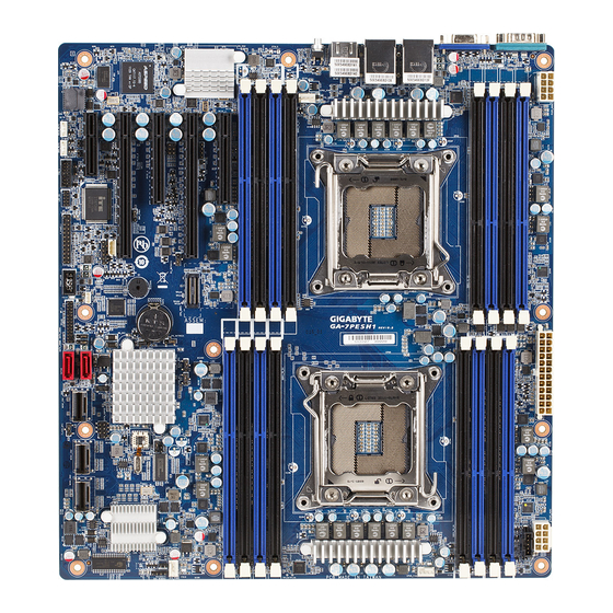
Page 6: Ga-7Pesh1/7Pesh2 Motherboard Layout
GA-7PESH1/7PESH2 Motherboard Layout 1 2 3 41 42 44 45 47 49 46 48 50 10 11 - 6 -... - Page 7 Item Code Description ID switch MLAN (GA-7PESH1) BMC Management LAN port USB_MLAN (GA-7PESH2) BMC Management LAN port (top) / USB ports (bottom) USB_LAN1 (GA-7PESH1) LAN1 port (top) / USB ports (bottom) GLAN1 (GA-7PESH2) LAN1 port USB_LAN2 (GA-7PESH1) LAN2 port (top) / USB ports (bottom)
- Page 8 PCIE_4 PCI-E slot 4 (x16 slot / x8 bus) BMC_LED1 BMC firmware readiness LED PCIE_3 PCI-E slot 3 (x8 slot / x4 bus) PCIE_2 PCI-E slot 2 (x16 slot/x16 bus) PCIE_1 PCI-E slot 1 (x8 slot / x4 bus) DDR3_P1_E0 Channel E slot 0 (for secondary CPU) DDR3_P1_E1 Channel E slot 1 (for secondary CPU) DDR3_P1_F0...
-
Page 9: Block Diagram
Block Diagram - 9 -... -
Page 10: Chapter 1 Hardware Installation
Chapter 1 Hardware Installation Installation Precautions The motherboard contains numerous delicate electronic circuits and components which can become damaged as a result of electrostatic discharge (ESD). Prior to installation, carefully read the user's manual and follow these procedures: • Prior to installation, do not remove or break motherboard S/N (Serial Number) sticker or warranty sticker provided by your dealer. -
Page 11: Product Specifications
Up to 6 USB 2.0/1.1 ports (4 on the back panel, 2 additional ports via the USB Š brackets connected to the internal USB headers/GA-7PESH1) Up to 4 USB 2.0/1.1 ports (2 on the back panel, 2 additional ports via the USB Š... - Page 12 AMI BIOS Š Form Factor EATX Form Factor; 12 inch x 13 inch, 8 layers PCB Š * GIGABYTE reserves the right to make any changes to the product specifications and product-related information without prior notice. Hardware Installation - 12 -...
-
Page 13: Installing The Cpu And Cpu Cooler
Read the following guidelines before you begin to install the CPU: • Make sure that the motherboard supports the CPU. (Go to GIGABYTE's website for the latest CPU support list.) • Always turn off the computer and unplug the power cord from the power outlet before installing the CPU to prevent hardware damage. - Page 14 B. Follow the steps below to correctly install the CPU into the motherboard CPU socket. • Before installing the CPU, make sure to turn off the computer and unplug the power cord from the power outlet to prevent damage to the CPU. •...
-
Page 15: Installing The Cpu Cooler
1-3-2 Installing the CPU Cooler Refer to the steps below to correctly install the CPU cooler on the motherboard. (Actual installation process may differ depending the CPU cooler to be used. Refer to the user's manual for your CPU cooler.) Step 1: Step 2: Apply an even and thin layer of thermal grease... -
Page 16: Installing The Memory
• Make sure that the motherboard supports the memory. It is recommended that memory of the same capacity, brand, speed, and chips be used. (Go to GIGABYTE's website for the latest supported memory speeds and memory modules.) • Always turn off the computer and unplug the power cord from the power outlet before installing the memory to prevent hardware damage. -
Page 17: Installing A Memory
1-4-2 Installing a Memory Before installing a memory module, make sure to turn off the computer and unplug the power cord from the power outlet to prevent damage to the memory module. Be sure to install DDR3 DIMMs on this motherboard. Installation Step: Step 1. -
Page 18: Back Panel Connectors
Back Panel Connectors GA-7PESH1 GA-7PESH2 Serial Port Connects to serial-based mouse or data processing devices. Video Port The video in port allows connect to video in, which can also apply to video loop thru function. RJ-45 LAN Port (Gigabit Ethernet LAN Port) The Gigabit Ethernet LAN port provides Internet connection at up to 1 Gbps data rate. -
Page 19: Hardware Installation
Link MLAN Speed LED: Link/Activity LED: Speed LED Activity LED State Description State Description Green On 100 Mbps data rate Link bet ween system and net work or no Green Blink 10 Mbps or 100 Mbps access data rate Blinking Data transmission or receiving is occurring 10/100 LAN Port 10 Mbps data rate No data transmission or receiving is occurring... -
Page 20: Internal Connectors
Internal Connectors ATX1 MINII_CN2 P12V_AUX2 MINII_CN3 P12V_AUX1 BP_1 PWR_DET1 TPM_1 CPU0_FAN (forprimary CPU) F_PANEL1 CPU1_FAN (for seconary CPU) IPMB1 SYS_FAN1 (System Fan) SATA_SGPIO SYS_FAN2 (System Fan) SKU_KEY1 SATA0/1 BAT1 FRONT_USB LED2 MINII_CN1 BMC_LED1 Hardware Installation - 20 -... - Page 21 Read the following guidelines before connecting external devices: • First make sure your devices are compliant with the connectors you wish to connect. • Before installing the devices, be sure to turn off the devices and your computer. Unplug the power cord from the power outlet to prevent damage to the devices.
- Page 22 1/2/3) ATX1/P12V_AUX2/P12V_AUX1 (2x4 12V Power Connector and 2x12 Main Power Connector) With the use of the power connector, the power supply can supply enough stable power to all the com- ponents on the motherboard. Before connecting the power connector, first make sure the power supply is turned off and all devices are properly installed. The power connector possesses a foolproof design. Connect the power supply cable to the power connector in the correct orientation.
- Page 23 4) PWR_DET1 (Power management connector) Pin No. Definition SMB CLK SMB DATA SMB Alert 3.3V Sense 5/6/7/8) CPU0_FAN/CPU1_FAN/SYS_FAN1/SYS_FAN2 (CPU Fan/System Fan Headers) The motherboard has a 4-pin CPU fan header (CPU_FAN1/2), a 4-pin (FAN4) system fan headers. Most fan headers possess a foolproof insertion design. When connecting a fan cable, be sure to connect it in the correct orientation (the black connector wire is the ground wire).
- Page 24 9) SATA0/SATA1 (SATA 6Gb/s Connectors) The SATA connectors conform to SATA 6Gb/s standard and are compatible with SATA 3Gb/s and 1.5Gb/s standard. Each SATA connector supports a single SATA device. When SATA_DOM1/2 jumper are set to Normal Mode: Pin No. Definition When SATA_DOM1/2 Jumper are set to 1-2 pin: Pin No. Definition...
- Page 25 11) MINI_CN1 (Mini SAS cable connector with SATA 3Gb/s signal) The SATA connectors conform to SATA 3Gb/s standard and are compatible with SATA 1.5Gb/s standard. Each SATA connector supports two SATA device. 12/13) MINI_CN2/MINI_CN3 (Mini SAS cable connectors) The mini SAS connectors conform to SAS 6Gb/s standard. MINI_CN1 MINI_CN2 MINI_CN3...
- Page 26 14) BP_1 (HDD Back Plane Board Hearder) Pin No. Definition AST2300_SCGCLK FM_THROTTLE_AND_N AST2300_SGLD IQO_FAN_12v_GATE_N AST2300_SGDOUT RresetL_BRB BP_ALED_N BP_LED_G_N 25 26 AST2300_SGDIN ASSESS#_LED_BPB SMB_BPB1_DATA SMB_BPB1_CLK P_3V3_AUX BP_HDD_TYPE P_3V3_AUX FAN_TYPE BP_PRESENSE 15) TPM_1 (TPM Module Connector) Pin No. Definition CLK_33M_TPM P_3V3_AUX LPC_RST_DEBUG P3V3 LPC_LAD0 IRQ_SERIAL LPC_LAD1 TPM_DET_N...
- Page 27 16) F_Panel1 (Front Panel Header) Connect the power switch, reset switch, speaker, chassis intrusion switch/sensor and system status indicator on the chassis to this header according to the pin assignments below. Note the positive and negative pins before connecting the cables. 23 24 Pin No. Signal Name Definition...
- Page 28 17) IPMB1 (IPMB connector) Pin No. Definition 18) SATA_SGPIO (SATA SGPIO Header) SGPIO is stands for Serial General Purpose Input/Output which is a 4-signal (or 4-wire) bus used be- tween a Host Bus Adapter (HBA) and a backplane. Out of the 4 signals, 3 are driven by the HBA and 1 is driven by the backplane.
- Page 29 19) SKU_KEY1 (Patsburg Upgrade ROM Hearder) Pin No. Definition FM_PBG_DYN_SKU_KEY 20) BAT1 (Battery) The battery provides power to keep the values (such as BIOS configurations, date, and time information) in the CMOS when the computer is turned off. Replace the battery when the battery voltage drops to a low level, or the CMOS values may not be accurate or may be lost. You may clear the CMOS values by removing the battery: 1.
- Page 30 21) LED2 (LSI Firmware Readiness LED) LED2 Link/Activity: State Description Blinking LSI firmware is ready LSI firmware is not ready 22) BMC_LED1 (BMC Firmware Readiness LED) State Description BMC firmware is initial Blinking BMC firmware is ready System is powered off Hardware Installation - 30 -...
-
Page 31: Jumper Setting
Jumper Setting CLR_CMOS1 BIOS_RCVR1 BIOS_WP1 SATA_DOM0 SSB_ME1 SATA_DOM1 FLASH_DP1 PASSWORD1 - 31 - Hardware Installation... -
Page 32: Clearing Cmos Jumper
1) CLR_CMOS1 (Clearing CMOS Jumper) Use this jumper to clear the CMOS values (e.g. date information and BIOS configurations) and reset the CMOS values to factory defaults. To clear the CMOS values, place a jumper cap on the two pins to temporarily short the two pins or use a metal object like a screwdriver to touch the two pins for a few seconds. - Page 33 3) SSB_ME1 (ME enable/disable Jumper) SSB_ME1 1-2 Close: Normal operation. (Default setting) 2-3 Close: Disable ME function. 4) JP5 (Case Open Intrusion Jumper) Open: Enable chassis intrusion alert. Close: Normal operation. (Default setting) - 33 - Hardware Installation...
- Page 34 5) PASSWORD1 (Skip Supervisor Password Jumper) 1-2 Close: Normal operation. (Default setting) 2-3 Close: Skip supervisor password. 6) BIOS_RVCR1 (BIOS Recovery Jumper) 1-2 Close: Normal operation. (Default setting) 2-3 Close: BIOS recovery mode. Hardware Installation - 34 -...
- Page 35 7/8) SATA_DOM0/1 (SATA DOM Jumper) CAUTION! If a SATA type hard drive is connected to the motherboard, please ensure the jumper is closed and set to 2-3 pins (Normal mode), in order to reduce any risk of hard disk damage. 1-2 Close: Enable SATA0/SATA1 port DOM support.
-
Page 36: Chapter 2 Bios Setup
Chapter 2 BIOS Setup BIOS (Basic Input and Output System) records hardware parameters of the system in the EFI on the moth- erboard. Its major functions include conducting the Power-On Self-Test (POST) during system startup, saving system parameters and loading operating system, etc. BIOS includes a BIOS Setup program that allows the user to modify basic system configuration settings or to activate certain system features. When the power is turned off, the battery on the motherboard supplies the necessary power to the CMOS to keep the configuration values in the CMOS. -
Page 37: Server Management
Main This setup page includes all the items in standard compatible BIOS. Advanced This setup page includes all the items of AMI BIOS special enhanced features. (ex: Auto detect fan and temperature status, automatically configure hard disk parameters.) Chipset This setup page includes all the submenu options for configuring the function of North Bridge and South Bridge. (ex: Auto detect fan and temperature status, automatically configure hard disk parameters.) Security Change, set, or disable supervisor and user password. Configuration supervisor password allows you to restrict access to the system and BIOS Setup. A supervisor password allows you to make changes in BIOS Setup. -
Page 38: The Main Menu
The Main Menu Once you enter the BIOS Setup program, the Main Menu (as shown below) appears on the screen. Use arrow keys to move among the items and press <Enter> to accept or enter other sub-menu. Main Menu Help The on-screen description of a highlighted setup option is displayed on the bottom line of the Main Menu. - Page 39 BIOS Information Project Version Display version number of the project. BMC Information BMC Firmware Version Display version number of the Firmware setup utility. SDR Reversion Display the SDR reversion information. FRU Reversion Display the FRU reversion information. Processor Information CPU Type/ Max CPU Speed/ CPU Signature / Processor Cores / Microcode Patch Displays the technical specifications for the installed processor.
-
Page 40: Advanced Menu
Advanced Menu The Advanced menu display submenu options for configuring the function of various hardware components. Select a submenu item, then press Enter to access the related submenu screen. BIOS Setup - 40 -... -
Page 41: Pci Subsystem Settings
2-2-1 PCI Subsystem Settings - 41 - BIOS Setup... -
Page 42: Perr Generation
PCI Express Slot 1/2/3/4/5 I/O ROM When enabled, This setting will initialize the device expansion ROM for the related PCI-E slot. Options available: Enabled/Disabled. Default setting is Enabled. Onboard LSI Oprom Enable/Disable onboard LSI option ROM. Options available: Enabled/Disabled. Default setting is Disabled. Onboard LAN1/2 Controller Enable/Disable Onboard LAN controller . -
Page 43: Pci Express Settings
2-2-1-1 PCI Express Settings PCI Express Device Register Settings Relaxed Ordering Enable/DIsable PCI Express Device Relaxed Ordering feature. Options available: Enabled/Disabled. Default setting is Disabled. Extended Tag Wnen this feature is enabled, the system will allow device to use 8-bit Tag field as a requester. Options available: Enabled/Disabled. Default setting is Disabled. No Snoop Enable/Disable PCI Express Device No Snoop option. Options available: Enabled/Disabled. - Page 44 Link Training Retry Define the number of Retry Attempts software wil take to retrain the link if previous training attempt was unsuccessful. Press <+> / <-> keys to increase or decrease the desired values. Link Training Timeout (us) Define the number of Microseconds software will wait before polling 'Link Training' bit in Link Status reg- ister. Press <+> / <-> keys to increase or decrease the desired values. Value rang is from 10 to 10000 Unpopulated Links When this item is set to 'Disable Link, the system will operate power save feature for those unpopulated PCI Express links.
-
Page 45: Runtime Error Logging
2-2-2 Runtime Error Logging Runtime Error Logging Enable/Disable Runtime error logging support. Options available: Enabled/Disabled. Default setting is Disabled. - 45 - BIOS Setup... -
Page 46: Cpu Configuration
2-2-3 CPU Configuration BIOS Setup - 46 -... - Page 47 CPU Information Socket 0/1 CPU Information CPU Type/ Signature / Microcode Patch / Max CPU Speed / Min CPU Speed / Processor Cores / Intel HT Technology / Intel VT-x Technology Displays the technical specifications for the installed processor. Intel HT Technology / Intel VT-x Technology Displays the support information for the installed processor. Cache Information L1 Data Cache / L1 Code Cache / L2 Cache / L3 Cache Displays the technical specifications for the installed processor.
-
Page 48: Execute Disable Bit
Limit CPUID Maximum When enabled, the processor will limit the maximum COUID input values to 03h when queried, even if the processor suppports a higher CPUID input value. When disabled, the processor will return the actual maximum CPUID input value of the processor when queried. -
Page 49: Cpu Power Management Configuration
2-2-3-1 CPU Power Management Configuration CPU Power Management Configuration Power Technology Configure the power management features. Options available: Disable/Energy Efficient/Custom. Default setting is Custom. EIST (Enhanced Intel SpeedStep Technology) Conventional Intel SpeedStep Technology switches both voltage and frequency in tandem between high and low levels in response to processor load. Options available: Enabled/Disabled. Default setting is Enabled. Turbo Mode When this item is enabled, tje processor will automatically ramp up the clock speed of 1-2 of its processing cores to improve its performance. -
Page 50: Energy Performance
CPU C3/C6 Report (Note) Allows you to determine whether to let the CPU enter C3/C6 mode in system halt state. When enabled, the CPU core frequency and voltage will be reduced during system halt state to decrease power con- sumption. The C3/C6 state is a more enhanced power-saving state than C1. Options available: Enabled/Disabled. -
Page 51: Usb Configuration
2-2-4 USB Configuration USB Configuration Legacy USB Support Enables or disables support for legacy USB devices. Options available: Auto/Enabled/Disabled. Default setting is Enabled. EHCI Hand-off Enable/Disable EHCI (USB 2.0) Hand-off function. Options available: Enabled/Disabled. Default setting is Disabled. - 51 - BIOS Setup... - Page 52 2-2-5 SATA Configuration BIOS Setup - 52 -...
-
Page 53: Sata Configuration
SATA Configuration SATA Port 0/1/2/3/4/5 (Note) Displays the installed HDD devices information. System will automatically detect HDD type. SATA Mode Selection Select the on chip SATA type. RAID Mode: When set to RAID, the SATA controllerenables both its RAID and AHCI functions. You will be allows access the RAID setup utility at boot time. -
Page 54: Info Report Configuration
2-2-6 Info Report Configuration Info Report Configuration Post Report Post Report Enable/Disable Post Report support. Options available: Enabled/Disabled. Default setting is Enabled. Error Message Report Info Error Message Enable/Disable Info Error Message support. Options available: Enabled/Disabled. Default setting is Disabled. BIOS Setup - 54 -... - Page 55 2-2-7 Super IO Configuration - 55 - BIOS Setup...
-
Page 56: Super Io Configuration
Super IO Configuration Super IO Chip Display the model name of Super IO chipset. Serial Port 0 Configuration Serial Port When enabled allows you to configure the serial port settings. When set to Disabled, displays no configuration for the serial port. Options available: Enabled/Disabled. Default setting is Enabled. Device Settings Displays the Serial Port base I/O address and IRQ. Change Settings Change Serial Port 0 device settings. When set to Auto allows the server’s BIOS or OS to select a con- figuration. -
Page 57: Serial Port Console Redirection
2-2-8 Serial Port Console Redirection - 57 - BIOS Setup... -
Page 58: Console Redirection Settings
COM1/Serial Port for Out-of Band Management / Windows Emergency Management Service (EMS) Console Redirection (Note) Select whether to enable console redirection for specified device. Console redirection enables users to manage the system from a remote location. Options available: Enabled/Disabled. Default setting is Disabled. Console Redirection Settings Terminal Type Select a terminal type to be used for console redirection. Options available: VT100/VT100+/ANSI /VT-UTF8. - Page 59 Parity A parity bit can be sent with the data bits to detect some transmission errors. Even: parity bi is 0 if the num of 1's in the data bits is even. Odd: parity bit is0if num of 1's the data bits is odd. Mark: parity bit is always 1.
-
Page 60: Network Stack
2-2-9 Network Stack Network stack Enable/Disable UEFI network stack. Options available: Enabled/DIsabled. Default setting is Disabled. BIOS Setup - 60 -... -
Page 61: Intel (R) I350 Gigabit Network Connection
2-2-10 Intel (R) I350 Gigabit Network Connection - 61 - BIOS Setup... - Page 62 PORT CONFIGURATION MENU NIC Configuration Link Speed Change link speed duplex for current port. Options available: AutoNeg/10Mbps Half/10Mbps Half/10Mbps Half/100Mbps Full. Default setting is AutoNeg. Wake On LAN Enable/Disable Wake On LAN feature. Options available: Enabled/DIsabled. Default setting is Enabled. Blink LEDs (range 0-15 seconds) Blink LEDs for the specified duration (up to 15 seconds).
-
Page 63: Chipset Menu
Chipset Menu The Chipset menu display submenu options for configuring the function of North Bridge and South Bridge. Select a submenu item, then press Enter to access the related submenu screen. - 63 - BIOS Setup... -
Page 64: North Bridge
2-3-1 North Bridge BIOS Setup - 64 -... -
Page 65: Ioh Configuration
IOH Configuration Press [Enter] for configuration of advanced items. QPI Configuration Press [Enter] for configuration of advanced items. Compatibility RID Enable/Disable Compatibility RID function. Options available: Enabled/Disabled. Default setting is Enabled. Memory Configuration Total Memory Displays the total capacity of the installed memory. Current Memory Mode Displays the current memory mode. Memory mode can be determined in Memory Mode item. Current Memory Speed Displays the current memory speed. -
Page 66: Demand Scrub
Options available: Enabled/Disabled. Default setting is Enabled. Demand Scrub Enable/Disable Demand Scrub function. Options available: Enabled/Disabled. Default setting is Disabled. Device Tagging Enable/Disable Device Tagging function. Options available: Enabled/Disabled. Default setting is Disabled. Rank Margin Enable/Disable Rank Margin function. Options available: Enabled/Disabled. Default setting is Disabled. Thermal Thortting Configure theThermal Thortting. - Page 67 2-3-1-1 IOH Configuration - 67 - BIOS Setup...
- Page 68 IOH Configuration Intel(R) VT for Directed I/O Configuration Press [Enter] for configuration of advanced items. Intel(R) I/OAT (Intel I/O Acceleration Technology) Enable/Disable Intel I/OAT function. Options available: Enabled/Disabled. Default setting is Disabled. DCA Support (Direct Cache Access) Enable/Disable Intel DCA Support function. Options available: Enabled/Disabled. Default setting is Disabled. VGA Priority Define the display device priority. Options available: Onboard/Offboard.
-
Page 69: Qpi Configuration
2-3-1-2 QPI Configuration Current QPI Link Speed/ Current QPI Link Freq Displays the current QPI Link Speed and Frequency information. Isoc Enable/Disable Isoc. Options available: Enabled/Disabled. Default setting is Disabled. QPI Link Speed Mode Configure QPI Link Speed mode. Options available: Fast/Slow. Default setting is Fast. QPI Link Frequency Select Configure QPI Link Frequency. -
Page 70: Dimm Information
2-3-1-3 DIMM Information CPU Socket 0/1 DIMM Information CPU Socket 0: DDR3_P0_A0/DDR3_P0_A1/DDR3_P0_B0/DDR3_P0_B1 Status DDR3_P0_C0/DDR3_P0_C1/DDR3_P0_D0/DDR3_P0_D1 Status The size of memory installed on each of the DDR3 slots. CPU Socket 1: DDR3_P0_E0/DDR3_P0_E1/DDR3_P0_F0/DDR3_P0_F1 Status DDR3_P0_G0/DDR3_P0_G1/DDR3_P0_H0/DDR3_P0_H1 Status The size of memory installed on each of the DDR3 slots. BIOS Setup - 70 -... -
Page 71: South Bridge Configuration
2-3-2 South Bridge Configuration PCH Information Name/Stepping Information Displays the name and stepping information of the south bridge. SB Chipset Configuration PCH Compatibility RID Enable/Disable PCH Compatibility RID support. Options available: Enabled/Disabled. Default setting is Disabled. Restore on AC Power Loss (Note) Defines the power state to resume to after a system shutdown that is due to an interruption in AC power. When set to Last State, the system will return to the active power state prior to shutdown. When set to Stay Off, the system remains off after power shutdown. -
Page 72: Intel Me Subsystem
2-3-3 Intel ME Subsystem ME Subsystem Configuration Enable/Disable ME subsystem configuration. Options available: Enabled/Disabled. Default setting is Enabled. BIOS Setup - 72 -... -
Page 73: Security Menu
Security Menu The Security menu allows you to safeguard and protect the system from unauthorized use by setting up ac- cess passwords. There are two types of passwords that you can set: • Administrator Password Entering this password will allow the user to access and change all settings in the Setup Utility. •... -
Page 74: Secure Boot Menu (Optional)
2-4-1 Secure Boot menu (Optional) The Secure Boot Menu is applicable when your device is installed the Windows 8 operatin system. ® Secure Boot menu Platform Mode Display the System Platform Mode State. Secure Boot Display the status of Secure Boot. Secure Boot Control Enable/Disable Secure Boot function. -
Page 75: Image Execution Policy
2-4-1-1 Image Execution Policy Image Execution policy Internal FV Image Execution Policy per device path on Security Violation. Options available: Always Execute. Default setting is Always Execute. Option ROM Image Execution Policy per device path on Security Violation. Options available: Always Execute/Always Deny/Allow Execute/Defer Execute/ Deny Execute/ Query User. -
Page 76: Key Management
2-4-1-2 Key Management Key Management This item appears only when the Secure Boot Mode is set to Custom. Default Key Provisioning Force the system to Setup Mode. This will clear all Secure Boot Variables such as Platform Key (PK), Key-exchange Key (KEK), Authorized Signature Database (db), and Forbidden Signaures Database (dbx). Options available: Enabled/Disabled. - Page 77 Get new KEK from File Press [Enter] to configure the existed KEK. Delete KEK Press [Enter] to delete the KEK from your system. Append an entry to KEK Press [Enter] to load additional KEK from a storage devices for an additional db and dbx management. Authorized Signature Database (DB) Display the status of Authorized Signature Database.
-
Page 78: Server Management Menu
Server Management Menu BMC LAN Configuration BMC LAN Configuration. Press Enter to access the related submenu. Gbt BMC Function BMC related function configuration.Press Enter to access the related submenu. View FRU information The FRU information submenu is a simple display page for basic system ID information, as well as sys- tem product information. Items on this window are non-configurable. System Event Log Displays Event Log advanced settings. Press Enter to access the related submenu. BIOS Setup - 78 -... -
Page 79: Bmc Lan Configuration
2-5-1 BMC LAN Configuration Lan Channel 1 Configuration Source Select to configure LAN channel parameters statically or dynamically (DHCP). Do nothing option willnot modify any BMC network parameters during BIOS phase. Options available: Static/Dynamic/Do Nothing. IP Address Display IP Address information. Subnet Mask Display Subnet Mask information. Please note that the IP address must be in three digitals, for example, 192.168.000.001. Default Gateway Address Display Default Gateway Address information. -
Page 80: Gbt Bmc Function
2-5-2 Gbt BMC Function Select NCSI and Dedicated LAN Switch NCSI and dedicated LAN and send KCS command. Options available: Mode2(NSCI)/ Mode1 (Dedicated). Default setting is Mode1 (Dedicated). BIOS Setup - 80 -... -
Page 81: View Fru Information
2-5-3 View FRU Information The System Management submenu is a simple display page for basic system ID information, as well as Sys- tem product information. Items on this window are non-configurable. - 81 - BIOS Setup... -
Page 82: System Event Log
2-5-4 System Event Log Enabling/Disabling Options SEL Components Change this to enable or disable all features of System Event Logging during boot. Options available: Enabled/Disabled. Default setting is Enabled. Erasing Settings Erasing SEL Choose options for erasing SEL. Options available: No/Yes, On next reset/Yes, On every reset. Default setting is No. When SEL is Full Choose options for reactions to a full SEL. -
Page 83: Boot Menu
Boot Menu The Boot menu allows you to set the drive priority during system boot-up. BIOS setup will display an error message if the legacy drive(s) specified is not bootable. Boot Configuration Setup Prompt Timeout Number of seconds to wait for setup activation key. 65535(0xFFFF) means indefinite waiting." Press the numberic keys to input the desired value. Bootup NumLock State Enable or Disable Bootup NumLock function. Options available: On/Off. - Page 84 Network Device BBS Priorities Press Enter to configure the boot priority. Hard Drive BBS Priorities Press Enter to configure the boot priority. CSM16 Parameters Press Enter to configure the CSM16 parameters. CSM Parameters Press Enter to configure the CSM parameters. BIOS Setup - 84 -...
-
Page 85: Csm16 Parameters
2-6-1 CSM16 Parameters CSM16 Parameters CSM16 Module Version Display CSM Module version information. Gate20 Active Upon Request: GA20 can be disabled using BIOS services. Always: Do not allow disabling GA20; this option is useful when any RT code is executed above 1MB. Options available: Upon Request/Always. -
Page 86: Csm Parameters
2-6-2 CSM Parameters CSM parameters Press Enter to configure the advanced items. CSM (Compatibility Support Module) Launch Enable/Disable Compatibility Support Module (CSM) launch. Options available: Enabled/Disabled. Default setting is Enabled. • The following five items appears and configurable when the Launch CSM is set to Enabled. • If the Launch CSM is set to Disabled, the following five items will not be able to support Legacy mode. - Page 87 Other PCI device ROM priority For PCI devices other than Network, Mass storage or Video device, defines which OpROM to launch. Options available: UEFI OpROM/Legacy OpROM. Default setting is UEFI OpROM. - 87 - BIOS Setup...
-
Page 88: Exit Menu
Exit Menu The Exit menu displays the various options to quit from the BIOS setup. Highlight any of the exit options then press Enter. Save Changes and Exit Saves changes made and close the BIOS setup. Options available: Yes/No. Discard Changes and Exit Discards changes made and close the BIOS setup. -
Page 89: Chapter 3 Appendix
Contravention will be prosecuted. We believe that the information contained herein was accurate in all respects at the time of printing. GIGABYTE cannot, however, assume any responsibility for errors or omissions in this text. Also note that the informa- tion in this document is subject to change without notice and should not be construed as a commitment by GIGABYTE. - Page 90 Finally, we suggest that you practice other environmentally friendly actions by understanding and using the energy-saving features of this product (where applicable), recycling the inner and outer packaging (including shipping containers) this product was delivered in, and by disposing of or recycling used batteries properly. With your help, we can reduce the amount of natural resources needed to produce electrical and electronic equipment, minimize the use of landfills for the disposal of "end of life" products, and generally improve our quality of life by ensuring that potentially hazardous substances are not released into the environment and...
Need help?
Do you have a question about the GA-7PESH1 and is the answer not in the manual?
Questions and answers