Table of Contents
Advertisement
Quick Links
Advertisement
Table of Contents

Subscribe to Our Youtube Channel
Summary of Contents for JR ProPo PCM9XII
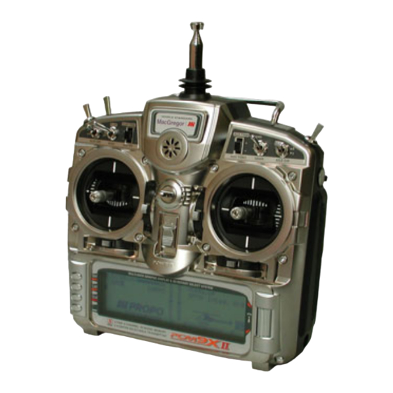
- Page 1 MACGREGOR INDUSTRIES Instruction Manual PCM9XII...
- Page 2 JR PROPO PCM9XII MacGregor Industries Ltd. wish to thank Horizon Hobbies for their permission to use sections of their XP-9303 Manuals when writing this PCM9XII Manual. MacGregor Industries Ltd. 2005 Canal Estate, Langley, Slough, SL3 6EQ Phone: 01753 549111 • Fax: 01753 546983...
-
Page 3: Table Of Contents
Table of Contents INTRODUCTION Standard Program Mix 3 to 6 Fail-safe Screen Contrast Adjustment Trainer Switch Warning Timer Throttle A.L.T. Servo Monitor Menu System Throttle Cut Transmitter Layout Helicopter Data Sheet Scroll Bar Interface Input Keys CHAPTER 3 Function Menu - Aero Advanced Digital Trim Control Stick Length Dual Rates &... - Page 4 This page is intentionally blank...
-
Page 5: Screen Contrast Adjustment
PCM9XII he JR PCM9XII uses the latest Computer and Display Screen technology to enhance and extend the Radio Control user's modelling experience. New to the PCM9X range is the Scroll Bar interface. In conjunction with the side entry buttons, the new Scroll Bar provides a quick, convenient and efficient programming environment. -
Page 6: Menu System
MENU SYSTEM The PCM9XII Transmitter settings and functions are controlled from within two major menu systems: SYSTEM MENU LIST - The menu contains settings such as wing type, switch assignment etc., relating to the model type. Some sections of the Function Menu only appear when their corresponding section is activated in the System Menu List. -
Page 7: Input Keys
These switch harnesses include the orange signal wire, as well as the brown and red power wires. BACKUP The PCM9XII no longer utilises a Lithium Battery for backup. Model settings are now stored on Flash Memory that is believed to have an unlimited life. -
Page 8: Battery Charging
FUSE The PCM9XII has a 3 amp internal fuse to protect the system in the event of a certain fault conditions. To replace the fuse, remove the RF Module, NiCad battery and back cover screws (six screws). Remove the transmitter back, being careful not to bend or damage the RF Module pins. -
Page 9: Model Select & Copy
The Model Selection screen appears. Model Memories can be accessed and copied. The PCM9XII has 30 Model Memories and any Model Memory can store details of any model type. The Copy function allows the contents of the current Model Memory to be copied into another Model Memory and should not be confused with the "TRANSFER"... -
Page 10: Model Name
Highlight the bottom model number by rotating the Scroll Bar and click to bring up the browse box of Receiving Model Memories. Highlight the required Receiving Model Memory by rotating the Scroll Bar and click to exit the sub menu. CAUTION: Be sure that the correct Model Memory is selected for the copy. -
Page 11: Data Reset
The Data Transfer enables the contents of the current Model Memory to be transferred to another PCM9XII transmitter or to receive data from another PCM9XII transmitter. It is also used to upload or download model data to a PC, using the... - Page 12 MacGregor DataXchange Software. A data transfer lead (Buddy Box Lead) is required to connect the two transmitters or the transmitter and the MacGregor DataXchange. Note: Model Memories can only be transferred to and from another PCM9XII. It is not possible to transfer data direct to a different model of transmitter.
-
Page 13: Trim Step
Trim Step To access the System Menu List (SYSTEM M.), start with the transmitter switched off. Press the ENT (Enter) key and while holding it down, switch the transmitter on. The System Menu List is displayed. Rotate the Scroll Bar to highlight the "TRIM STEP"... -
Page 14: Device Select - Aero Mode
Together with the Wing Type (Wing TYPE) section, the Device Select (DeviceSEL) screen provides access to the heart of the PCM9XII transmitter. • Flight Modes may be enabled and their associated activation switches selected. • The primary channel Digital Trim positions and the Dual Rates may be associated with (controlled by) the Flight Modes. - Page 15 (FM0) is active when the Flight Mode switch is in the "0" or "N" position, Flight Mode 1 (FM1) is active when the Flight Mode switch is in the "1" position and Flight Mode 2 (FM2) is active when the Flight Mode switch is in the "2" position. The TRIM:FM and D/R: FM selections only appear when Flight Modes are active.
-
Page 16: Device Select - Glider Mode
If any of the Auxiliary Channels are to be used as a Mate in the Dual servo facility, (see the Wing Type section), they must first be made available by inhibiting their output. Inhibiting the output may also be necessary for some Programme Mix operations. - Page 17 To Select an Activation Switch/inhibit the Speed Flight Mode, highlight SPEED by rotating the Scroll Bar and click on it to bring up the sub menu. The activation switch choices are surrounded by a box to indicate activation. Select the required Flight Mode activation switch by rotating the Scroll Bar and click on it to activate the selection.
-
Page 18: Wing Type - Aero Mode
Together with the Device Select (DeviceSEL) section, the Wing Type (Wing TYPE) screen provides access to the heart of the PCM9XII transmitter. • Flaperon (Ailerons also as Flaps) wing type may be selected. • Delta (Ailerons and Elevator combined) wing type may be selected. - Page 19 Ailerons and in the same direction as Flaps. Please note that if Dual Servos are required for the Ailerons, without the Flap input, the Dual Aileron facility may be used. With the Delta Wing configuration, the left wing servo plugs into the Aileron channel on the receiver (Port 2) and the right wing servo plugs into the Elevator channel (Port 3).
-
Page 20: Wing Type - Glider Mode
If FLAP or AUX3 are selected as the Mate, an extra menu choice appears in line with Trim. If enabled, the associated Digital Trim control (FLAP TRIM or AUX TRIM) will differentially trim both servos. To enable the differential trim, select the appropriate INH, in line with Trim by rotating the Scroll Bar and click to toggle the selection between ACT (active) and INH (inhibited). -
Page 21: Swash Type - Helicopter Mode
"SWASH TYP" menu choice and click to bring up the sub menu. The PCM9XII provides six types of Cyclic Collective Pitch Mixing (CCPM). The Normal mode (1sNORM) uses separate servos for the Aileron, Elevator and Pitch inputs and the other modes electronically mix the stick inputs to move the servos to give the required helicopter response. -
Page 22: Stick Direction
To move the Ratchet Bar (convert mode 2 (4) to mode 1 (3)), remove the RF Module and NiCad battery. Carefully unscrew and remove the back cover (six screws). Remove the transmitter back, being careful not to bend or damage the RF Module pins. -
Page 23: Dual Rates & Exponential
Chapter Function Menu List - Helicopter The Function Menu List is accessed from the Information Display Screen by pressing the LIST key. Dual Rates & Exponential From the Function Menu List, rotate the Scroll Bar to highlight the "D/R & EXP" menu choice and click the Scroll Bar. •... -
Page 24: Servo Reverse
To select the Flight Mode rate, highlight the required Flight Mode on the right of the screen, by rotating the Scroll Bar and click on it to bring up the sub menu choices. A browse box gives the sub menu choices. The default is to have the rates controlled by the rate switches (INH). -
Page 25: Travel Adjust
To change the sub trim value, highlight the required channel by rotating the Scroll Bar and click on it to bring up the sub menu. The highlighting is surrounded by a box to indicate that it is selected. Rotate the Scroll Bar to alter the setting. To return the figures to the default of zero, press the clear (CLR) key at the left hand side of the screen. -
Page 26: Throttle Hold
To change the CCPM travel, highlight the required CCPM channel by rotating the Scroll Bar and click on it to bring up the sub menu. The channel is surrounded by a box to indicate that it is selected. Rotate the Scroll Bar to alter the setting. To return the figures to the default of 60%, press the clear (CLR) key at the left hand side of the screen. -
Page 27: Throttle Curve
Menu List, rotate the Scroll Bar to highlight the "THRO CURV" menu choice and click the Scroll Bar. The PCM9XII offers up to five separate Throttle curves with up to seven adjustable points in each (high, low and five intermediate points). The Throttle curve can be tailored to suit the engine torque curve and so maximise engine performance. -
Page 28: Pitch Curve
Menu List, rotate the Scroll Bar to highlight the "PIT. CURV" menu choice and click the Scroll Bar. The PCM9XII offers up to six separate pitch curves with up to seven adjustable points in each (high, low and five intermediate points). The Pitch curve can be tailored to suit the engine torque curve and so maximise engine performance. -
Page 29: Revolution Mixing
The Revolution Mixing function is designed for use with conventional "Rate" gyros only. When set up correctly, the helicopter should climb and descend without a tendency to yaw in either direction. The PCM9XII offers two separate revolution mixing programs, with independent up and down mixing , one for the normal Flight Mode and the other for the Stunt modes. -
Page 30: Jr G490T Gyro Set-Up
To select an activation switch, highlight "INH" (or previous selection) at the top left of the screen by rotating the Scroll Bar and click on it to bring up a browse box of the available choices. Rotate the Scroll Bar to highlight the required activation method and click to exit the sub menu. -
Page 31: Cyclic To Throttle Mix
Menu List, rotate the Scroll Bar to highlight the "MIX->THRO" menu choice and click the Scroll Bar. The PCM9XII's Cyclic-to-Throttle function is designed to correct any under-speeding or over-speeding of the main rotor due to load changes placed upon the engine when an Aileron, Elevator, or Rudder control is given. By using the Cyclic-to- Throttle mixing, the main rotor RPM can be held at a constant value throughout aerobatic and 3D manoeuvres. - Page 32 To select an activation switch, highlight "SW SEL" under the required Cyclic mix by rotating the Scroll Bar and click on it to bring up a browse box of the available choices. Rotate the Scroll Bar to highlight the required activation switch and click to toggle the selection between OFF and ON.
-
Page 33: Governor
Menu List, rotate the Scroll Bar to highlight the "GOVENOR" menu choice and click the Scroll Bar. The PCM9XII's Governor function allows an individual governor rpm value to be set for each of the Flight Modes and for Throttle Hold by providing a travel adjustment for each switch position. The percentage value exactly corresponds to the Travel Adjust figures. - Page 34 and the Slave always moves by the same amount relative to the input stick or switch and the Trim mix (+ mix), where the Master input trim is included in the Slave output. When activated, the default for mixes 1 and 2, with the graph line running from bottom left to top right gives, a linear response with the Slave channel exactly replicating the Master channel over the entire Master input range.
- Page 35 click on it to toggle between "0N" and "OFF". The black indicator square moves between the bottom of the box (OFF) and the top of the box (ON) to indicate the current selection. To deactivate any switch selection and return the mix to permanently on, select and click on "ON".
- Page 36 Please note that the actual Master and Slave channel selection displayed will depend on the settings made in System Mode - DeviceSEL and SWASH TYP. To activate the mix, select and click on INH or press the CLR key on the left of the screen. The default is for THRO (Throttle) to be mixed to THRO (Throttle).
-
Page 37: Fail-Safe
Please note that ST3 and ST4 (Additional Flight Modes) switch selections will only appear if F.MOD EXTRA has been activated in System Mode - DeviceSEL. The HLD (Throttle Hold) selection will only appear when Throttle Hold is active. Notice that for information, when a switch/Flight Mode is selected to activate/deactivate the mix, the figure to the right of [PROG.Mix] on the top left of the screen changes from 0 to 1 as the activation switch is moved. -
Page 38: Trainer
Servo Reverse, Travel Adjust and any mixes are taken from the Master transmitter. The PCM9XII also has a special Slave mode where the modulation is automatically set to PPM and all of the control settings are set to the default ready for use with the Programmable Function Trainer (P.F.T.) - Page 39 Travel Adjustments and mixes etc. will be taken from the Master Transmitter and the Slave Transmitter must be reset to its default. This happens automatically when the PCM9XII is used in Slave mode. Due to slight errors in set-up, occasionally there may be slight control surface deflection as the Trainer switch is operated.
-
Page 40: Timer
The PCM9XII contains two timers. One is an integrated timer that keeps track of total transmitter-on time for the current model and the other can be configured as a Countdown Timer or as a Stopwatch. The elapsed time always shows on the Information Display Screen(hours and minutes) and when active, the Countdown or Stopwatch timer also appears on the Information Display Screen and can be started, stopped and reset from there. -
Page 41: Servo Monitor
When the engine stops, the trim can be returned to the centre ready for the next engine start. This is not possible with normal Digital Trims. The PCM9XII has the choice of an Intelligent Throttle Trim or a Throttle Cut function. - Page 42 a servo position about 25% below the normal Throttle low position. Figures between ± 25% may be entered with -25% corresponding to the absolute minimum servo movement and +25% corresponding to 50% above the normal tick-over position. Rotate the Scroll Bar to alter the setting. When the required setting is achieved, click the Scroll Bar to exit the sub menu.
-
Page 43: Helicopter Data Sheet
39 HELI... -
Page 44: Dual Rates & Exponential
Chapter Function Menu List - Aircraft The Aero Mode has facilities particularly relevant to Aero Models. There are three Flight Modes where almost all flight parameters may be individually set, including the Active Digital Trims, where the settings can be automatically remembered for each Flight Mode. -
Page 45: Servo Reverse
To change the linearity, highlight the required position (Pos-0 LIN, Pos-1 LIN or Pos-2 LIN) by rotating the Scroll Bar and click on it to bring up the sub menu choices. The highlighting is surrounded by a box to indicate that it is selected. The right hand side of the screen displays a graphical representation of the response curve. -
Page 46: Travel Adjust
Travel Adjust The Function Menu List is accessed from the Information Display Screen by pressing the LIST key. From the Function Menu List, rotate the Scroll Bar to highlight the "TRVL ADJ." menu choice and click the Scroll Bar. Travel Adjust, (Endpoint Adjustment/Travel Volume), sets the movement of the servo arm. The travel adjust range is from zero to 150% with individual adjustment in each direction. -
Page 47: Aileron To Rudder Mix
Throttle and 100 corresponding to full Throttle. To inhibit the Throttle activation (INH), press the clear (CLR) key. When the required setting is achieved, click the Scroll Bar to exit the sub menu. For information, the figure to the right of [ELE -> FLP M] on the top left of the screen changes from a “0” (position 0 value) to “1”... - Page 48 The Throttle curve can also be used to give a special Throttle response where the engine quickly comes up to a certain RPM and then advances slowly to provide precise RPM control for a specific Throttle range, before continuing on to full Throttle.
-
Page 49: Flap System
To set a Throttle curve point, highlight the required point by rotating the Scroll Bar and click on it to bring up the sub menu. The highlighting is surrounded by a box to indicate that it is selected. Rotate the Scroll Bar to alter the setting. When the required setting is achieved, click the Scroll Bar to exit the sub menu. - Page 50 To set an Elevator compensating value, highlight the required switch position adjacent to "ELEV" at the top of the screen by rotating the Scroll Bar and click on it to bring up the sub menu. The figure is surrounded by a box to indicate that it is selected.
-
Page 51: Snap Roll
Menu List, rotate the Scroll Bar to highlight the "GYRO SYS." menu choice and click the Scroll Bar. The PCM9XII features a very sophisticated Gyro Gain Sensitivity System that allows in-flight selection of three individual gyro gain settings for two separate gyros. Fixed gain values as well as a Stick Override Gain, (where gyro gain is progressively reduced as the stick is moved away from centre), are available. - Page 52 The top half of the screen shows the AUX2 settings and the bottom half of the screen shows the AUX3 settings. Please note that the Flight Mode switch choices "FM0:", "FM1:" and "FM2:" will only appear if Flight Modes have been activated in System Mode - DeviceSEL. The screen will vary according to the number of channels selected for Gyro gain.
-
Page 53: Aileron Differential
Aileron Differential Please note that the "AIL Diff." menu choice will only appear if the FLAPERON Wing Type has been selected in System Mode - Wing TYPE or a Dual channel has been assigned to Ailerons in System Mode - Wing TYPE. The Function Menu List is accessed from the Information Display Screen by pressing the LIST key. - Page 54 The servo speed function is very useful for scale models with retractable landing gear and gear doors, since in many instances, the need for gear door sequencers can be eliminated. If the gear door servos move at normal speed and the landing gear servos move at a slower speed when the gear is lowered, the gear doors will be open before the landing gear begins to come down.
-
Page 55: Multipoint Program Mix 1 And
To set a Throttle stick activation point, highlight the THRO STK menu choice by rotating the Scroll Bar and click on it to bring up the sub menu. The words are surrounded by a box to indicate that they are selected. Rotate the Scroll Bar to alter the setting. - Page 56 Slave Channel Identification. THRO Throttle channel. FLAP Flap channel. AILE Aileron channel. AUX2 Auxiliary 2 channel. ELEV Elevator channel. AUX3 Auxiliary 3 channel. RUDD Rudder channel. AUX4 Auxiliary 4 channel. GEAR Gear channel. FPRN Flaperon function (both Ailerons as Flaps). To activate the mix, select and click on INH or press the CLR key on the left of the screen.
-
Page 57: Standard Program Mix 3 To
will use the Pos1 values when the Throttle stick is below the setting point and the Pos0 values when it is above the setting point. To select an exponential (smoothed) curve, highlight the OFF under EXP menu by rotating the Scroll Bar and click on it to toggle between OFF and ON. - Page 58 Slave Channel Identification. THRO Throttle channel. FLAP Flap channel. AILE Aileron channel. AUX2 Auxiliary 2 channel. ELEV Elevator channel. AUX3 Auxiliary 3 channel. RUDD Rudder channel. AUX4 Auxiliary 4 channel. GEAR Gear channel. FPRN Flaperon function (both Ailerons as Flaps). To activate the mix, select and click on INH or press the CLR key on the left of the screen.
-
Page 59: Fail-Safe
Notice that when a switch/Flight Mode is selected to activate/deactivate the mix, the figure to the right of [PROG.Mix] on the top left of the screen changes from 0 to 1 as the activation switch is moved. Switch Identification: Flight Mode 0. (Appears when Flight Modes have been activated in System Mode - DeviceSEL.) Flight Mode 1. -
Page 60: Trainer
Servo Reverse, Travel Adjust and any mixes are taken from the Master transmitter. The PCM9XII also has a special Slave mode where the modulation is automatically set to PPM and all of the control settings are set to the default ready for use with the Programmable Function Trainer (P.F.T.) - Page 61 Travel Adjustments and mixes etc. will be taken from the Master Transmitter and the Slave Transmitter must be reset to its default. This happens automatically when the PCM9XII is used in Slave mode. Due to slight errors in set-up, occasionally there may be slight control surface deflection as the Trainer switch is operated.
-
Page 62: Timer
The PCM9XII contains two timers. One is an integrated timer that keeps track of total transmitter-on time for the current model and the other can be configured as a Countdown Timer or as a Stopwatch. The elapsed time always shows on the Information Display Screen (hours and minutes) and when active, the Countdown or Stopwatch timer also appears on the Information Display Screen and can be started, stopped and reset from there. -
Page 63: Servo Monitor
When the engine stops, the trim can be returned to the centre ready for the next engine start. This is not possible with normal Digital trims. The PCM9XII has the choice of an Intelligent Throttle Trim or a Throttle Cut function. - Page 64 To set a Throttle Cut position, select INH under THRO Cut by rotating the Scroll Bar and click on it to toggle between activated (ACT) and inhibited (INH). If Intelligent Throttle Trim has been previously activated, it will be inhibited automatically.
-
Page 65: Aircraft Data Sheet
61 AERO... -
Page 66: Dual Rates & Exponential
Chapter Function Menu List - Glider Aircraft The Glider Mode has facilities particularly relevant to Glider Models with a 4 servo wing. There are five Flight Modes where almost all flight parameters may be individually set, including Active Digital Trim, where the settings can be automatically remembered for each Flight Mode. -
Page 67: Servo Reverse
To change between channels, highlight the channel menu choice (AILE on the graphic above) by rotating the Scroll Bar and click on it to bring up a browse box with the sub menu choices. Move between the sub menu choices by rotating the Scroll Bar. -
Page 68: Sub Trim
To change the channel movement direction, highlight the required channel by rotating the Scroll Bar and click on it to toggle between normal and reversed. The black direction indicator square moves between the top of the box (reversed) and the bottom of the box (normal) to indicate the current selection. When the required setting is achieved, click the Scroll Bar to exit the sub menu. -
Page 69: Elevator To Flap Mix
Please note that the channel names shown will depend on the selections made in System Mode - Wing TYPE. To set a travel value, highlight the required figure by rotating the Scroll Bar and click on it to bring up the sub menu. Pairs of figures are surrounded by a box to indicate that they are selected. -
Page 70: Aileron To Flap Mix
Aileron to Flap Mix Please note that the Aileron to Flap mix menu choice only appears when Dual Flaps are enabled in the System Mode - Wing TYPE as two Flap servos are necessary to perform the functions available to dual Ailerons. The Function Menu List is accessed from the Information Display Screen by pressing the LIST key. -
Page 71: Flight Mode Delay
Please note that the display will only show the Flight Modes activated in System Mode - DeviceSEL. Press the LIST key to return to the Function Menu. Press the enter (ENT) key to return to the Information Display Screen. Flight Mode Delay The Function Menu List is accessed from the Information Display Screen by pressing the LIST key. -
Page 72: Aileron To Rudder Mix
The Flaperon mix enables the Ailerons to additionally act as Flaps to increase the Flap authority and effectively have full length Flaps. This can improve the performance when using a slight reflex Flap (wing trailing edge raised) for speed or a slight camber Flap (wing trailing edge lowered) for thermal soaring. -
Page 73: Butterfly Mix
the default of 0, press the clear (CLR) key at the left hand side of the screen. When the required setting is achieved, click the Scroll Bar to exit the sub menu. Please note that the display will only show the Flight Modes activated in System Mode - DeviceSEL. Press the LIST key to return to the Function Menu. -
Page 74: Flap Rate
To select an activation switch, highlight SW SELECT by rotating the Scroll Bar and click to activate the sub menu. A browse box will appear containing the available switches. Highlight the required switch by rotating the Scroll Bar and click on it to toggle between position "0"... -
Page 75: Multipoint Program Mix 1 And
The Function Menu List is accessed from the Information Display Screen by pressing the LIST key. From the Function Menu List, rotate the Scroll Bar to highlight the "MOTO.HOLD" menu choice and click the Scroll Bar. The Motor Hold facility enables a switch to be used to move the Throttle servo (Motor) to a pre-set position irrespective of the Throttle (Spoiler) stick position. - Page 76 The mix can be permanently active, or enabled and disabled by the Flight Modes and other switches. When the mix is activated by a switch, the Pos1 values always take priority over the Pos0 values. If multiple switches are selected and one of the switches is in the POS1 position, then all other switches are ignored and the Pos1 values are used.
- Page 77 Master Channel Identification: FPRN Flaperon Function. #AIL Aileron stick Origin Mix. AILE Aileron channel. #ELE Elevator stick Origin Mix. ELEV Elevator channel. #RUD Rudder stick Origin Mix. RUDD Rudder channel. ELE+ Elevator channel incl. trim. MOTO Motor channel (Gear). #FLP Flap channel Origin mix.
- Page 78 Program Mixes 3 to 6. The Function Menu List is accessed from the Information Display Screen by pressing the LIST key. From the Function Menu List, rotate the Scroll Bar to highlight the "PROG.Mix" menu choice and click the Scroll Bar. The default is for the mixes to be inhibited.
- Page 79 To select a Master channel, highlight the left hand FPRN (or previously selected Master channel) by rotating the Scroll Bar and click on it to bring up the sub menu. A browse box of the available Master channels appears with a heading of "Mast"...
-
Page 80: Fail-Safe
Fail-safe Please note that the Fail Safe menu choice will only appear in the Function Menu when SPCM or ZPCM modulation types are selected in System Mode - MODULAT. The Function Menu List is accessed from the Information Display Screen by pressing the LIST key. From the Function Menu List, rotate the Scroll Bar to highlight the "Fail Safe"... -
Page 81: Trainer
Servo Reverse, Travel Adjust and any mixes, are taken from the Master transmitter. The PCM9XII also has a special Slave mode where the modulation is automatically set to PPM and all of the control settings are set to the default ready for use with the Programmable Function Trainer (P.F.T.) -
Page 82: Timer
Menu List, rotate the Scroll Bar to highlight the "TIMER" menu choice and click the Scroll Bar. In Glider mode, the PCM9XII contains a Timer System with three timers. One is an integrated timer that stores the total transmitter-on time for the current model - displayed as "Integ." time on the Information Display Screen. The other timers can be configured as Countdown or Stopwatch. - Page 83 When the Countdown Timer is active, the transmitter will beep three times at 30 seconds, twice at 20 seconds, and then once every second from 10 seconds to zero. At zero there will be a continuous tone for 1 second and then the timer will begin counting up with a "+"...
-
Page 84: Servo Monitor
Switch Identification: AIL D/R Aileron Dual Rate switch. TIME SW Trainer switch. ELE D/R Elevator Dual Rate switch. MOTO SW Motor (Gear) switch. RUD D/R Rudder Dual Rate switch. TIM KEY Timer key (bottom key). BTFL SW Butterfly (Mix/Hold) switch. Press the LIST key to return to the Function Menu. -
Page 85: Glider Data Sheet
81 GLIDER... - Page 86 This page is intentionally blank...
- Page 87 This page is intentionally blank...
- Page 88 E&OE Please note that while every effort has been taken to ensure the accuracy of the information contained in this booklet, errors may occur. MacGregor Industries Limited accept no responsibility for losses or damage caused.
Need help?
Do you have a question about the PCM9XII and is the answer not in the manual?
Questions and answers