Table of Contents
Advertisement
Advertisement
Table of Contents

Summary of Contents for Zentron 6300
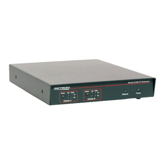
- Page 1 Model 6300 IP Gateway 025-9631D.1...
-
Page 2: Limited Warranty
Software License The Zetron software described in this manual is subject to the terms and conditions of Zetron’s Software License Agreement, a copy of which is contained on the product distribution media or otherwise provided or presented to buyer. Installation and/or use of the Zetron software constitutes acceptance of Zetron’s Software License Agreement. Contains software BSD Unix, Copyright ©... -
Page 3: Regulatory Compliance
Regulatory Compliance FCC Class A User Information This equipment has been tested and found to comply with the limits for a Class A digital device, pursuant to Part 15 of the FCC Rules. These limits are designed to provide reasonable protection against harmful interference when the equipment is operated in a commercial environment. - Page 4 Safety Summary Warning! For your safety and the protection of the equipment, observe these precautions when installing or servicing Zetron equipment. • Follow all warnings and instructions marked on the equipment or included in documentation. • Only technically qualified service personnel are permitted to install or service the equipment. •...
-
Page 5: Table Of Contents
Contents Contents Introduction .......................8 System Overview ........................8 Specifications......................... 9 Physical Dimensions...................... 9 Inputs and Outputs....................... 10 Cable..........................11 Environmental and Power Requirements ..............11 Mean Time Between Failures ..................11 Compatibility ........................11 Operator Control Equipment ..................11 Radio Compatibility ...................... 12 Network Compatibility .................... - Page 6 Configuring Two IP Gateways on a Local Area Network (LAN).......... 31 System Parameters for Model 6300 #1:..............32 Link 1 Parameters for Model 6300 #1: ................ 32 System Parameters for Model 6300 #2:..............33 Link 1 Parameters for Model 6300 #2: ................ 33 Summary of Settings ....................
- Page 7 Contents Using the Internet ........................ 57 Index ........................58...
-
Page 8: Introduction
System Overview The Zetron Model 6300 IP Gateway is a “Radio over IP” (RoIP) device that provides a means of connecting radio consoles with radios, or radios with radios by way of an IP network instead of traditional dedicated wire connections or microwave radio. -
Page 9: Specifications
Specifications The following figure provides two simple examples of the Model 6300 used to connect legacy radio equipment and intercoms across an IP network. Figure 1 – Model 6300 example configurations IP Network Model 6300 Model 6300 Operator Control IP Gateway... -
Page 10: Inputs And Outputs
Introduction Stand-alone The IP Gateway can also be placed as a stand-alone unit. Figure 3 – Stand-alone IP Gateways Model 6300 IP Gateway Status Radio Status Radio Network Power Link 1 Link 2 +13.5VDC/GND +13.5VDC/GND Tone Remote Radio A Radio B... -
Page 11: Cable
500mA @ 10.5VDC Operating Temperature 5 to 55 degrees C (41 to 131 F) The Model 6300 IP Gateway uses Zetron power supply P/N 950-0406. It is also compatible with Zetron Redundant 12VDC Power System Kits P/N 950-1142 and 950-1143. -
Page 12: Radio Compatibility
Network Compatibility Several network parameters such as the type of switches, overall network speed, and prioritization settings have a direct, measurable effect on a system using Model 6300 IP Gateways. The following list identifies specific requirements. Caution! -
Page 13: Licensed Features
Licensed Features BSI Protocol (US Department of The Model 6300 requires a license to enable the Homeland Security Bridging System Interface). The BSI Protocol can each be licensed separately for one or both links. -
Page 14: Heed Warnings
Introduction Heed Warnings Adhere to all warnings on the equipment and in the operating instructions. Follow all operating and use instructions. Mounting Mount the equipment only as recommended by the manufacturer (see Mounting on page 17). Situate the equipment away from heat sources such as radiators, heat registers, stoves, and other devices (including amplifiers) that produce heat. - Page 15 Safety...
-
Page 16: Physical Installation
Physical Installation Physical Installation Overview This chapter covers installation of the IP Gateways, including initial configuration. Required Tools The following tools may be required during installation. • Screwdriver set • Wire crimping tool • RJ11/RJ45 crimping tool 025-9631D.1... -
Page 17: Mounting
In the rack-mount configuration, there are one or two IP Gateways per mounting plate. The following diagram shows two IP Gateways in a dual unit rack mount plate (P/N 950- 0588). A single unit rack mount plate is also available (P/N 950-0589). Model 6300 IP Gateway Model 6300 IP Gateway Status... -
Page 18: Dip Switches
Physical Installation DIP Switches Each IP Gateway has four DIP switches at the rear that must be configured before power is applied. The following table describes the purpose of each of the DIP switches for troubleshooting and reference purposes. For most purposes, the switches can be left in their default positions. -
Page 19: Jumpers
Jumpers Jumpers Table 2 – Model 6300 jumper settings Jumper Position Purpose A: Normal* These jumpers must be moved together to set the signal to inverted B: Non-inverted or non-inverted for Link A. Installed: Enable flashing Install the jumper during the procedure to add licenses. Otherwise, Removed: Write-protect* the jumper should be removed. -
Page 20: Connections
Physical Installation Connections +13.5VDC/GND +13.5VDC/GND Tone Remote Radio A Radio B Network Network Pin 1 Balanced Audio Link 1 Link 2 A B C D A B C D Power Port Power should be applied only after jumpers and switches are set, and after the other cables have been connected. -
Page 21: Link 1 And Link 2 Ports
Connections Link 1 and Link 2 Ports The Model 6300 IP Gateway is compatible with radios using RS-232 or TTL signaling. It can also be used with radios using other methods of signaling, such as RS-422 or RS-485, when installed with proper converters. -
Page 22: System Configuration
Green IP Gateway is booting firmware image B. IP Gateway is booting failsafe firmware image. Once the IP Gateway has fully booted, it has reached a quiescent state. IP Gateway LEDs Model 6300 IP Gateway Status VoIP Analog Status VoIP... -
Page 23: Led Description
Initial Configuration Table 5 - IP Gateway LED behavior Description Status Green = The IP Gateway is paired with another IP Gateway Amber = The IP Gateway cannot detect a paired IP Gateway VoIP TX = The IP Gateway is sending IP data on this link RX = The IP Gateway is receiving IP data on this link Analog TX = The IP Gateway is sending a transmission on this link... -
Page 24: Http Configuration
System Configuration b. Clear the checkbox for Use a proxy server for your LAN. c. Click OK to close the settings windows. 2. Configure TCP/IP settings in Windows: a. Click Start, Control Panel, Network Connections, Local Area Connection, Properties. b. Click Internet Protocol (TCP/IP), then Properties. c. - Page 25 Initial Configuration Some settings reveal or hide other settings. When using Internet Explorer, it is often necessary to click elsewhere on the screen after making a selection before that selection is considered active. ♦ To configure the IP Gateway System Parameters 1.
- Page 26 System Configuration 6. The following system parameters require configuration: • IP Address • Netmask • IP Gateway The remainder of the system parameters can be left at their defaults or adjusted according to your preferences. The following table describes the purpose of each system parameter. Table 6 - IP Gateway system parameters Parameter Purpose...
- Page 27 Initial Configuration If you need to continue configuration after changing the IP address, you must use the IP Gateway’s IP address to access the web-based configuration pages. Using the old IP address or trying the browser’s refresh/reload button will not work. Also, you may have to change the computer’s TCP/IP settings to be compatible with the IP Gateway’s new IP address.
-
Page 28: Recommended Analog Line Settings
Overview This chapter describes the recommended configuration settings for the three most common radio applications of the Model 6300: 1. Extending a 4-wire balanced circuit with in-band control (e.g. tone remote control) between a fixed radio and its wireline control equipment (e.g. desktop remote or dispatch console). -
Page 29: 4-Wire/Tone Remote Control Configuration
In a four-wire scenario, radio control is accomplished by in-band tones, such as tone remote control. In this scenario the Model 6300’s COR and PTT signals are not used. Because of this VOX detection must be relied upon to detect the presence of incoming audio so as to initiate a VoIP connection with the remote paired link. -
Page 30: 8-Wire/E&M Control/Radio Bridging Configuration
In this scenario, radio control is accomplished by the use of an external PTT signal rather than by in-band control tones. Because two radios are being bridged the Model 6300’s COR and PTT signals are used in both directions. Because VOX is not used, it is not necessary to enable Full Duplex operation. -
Page 31: Connecting Two Ip Gateways
Overview Connecting Two IP Gateways Overview This chapter describes how to connect and configure the links for two Model 6300 IP Gateways in order for them to operate over Local Area Network (LAN) or a Wide Area Network (WAN). Configuring Two IP Gateways on a Local Area Network (LAN) -
Page 32: System Parameters For Model 6300 #1
Given the LAN above, here is how you would configure the RoIP Gateway parameters to allow Link 1 of the Model 6300 #1 to be paired with Link 1 of the Model 6300 #2. System Parameters for Model 6300 #1: For a full description of each setting on the Link Configuration pages, see Table 6 on page 26. -
Page 33: System Parameters For Model 6300 #2
RTP Send Port Number: 4004. This should match the RTP Send Port Number of the paired Link (Link 1 of Model 6300 #1). The RTP port number must be even because the companion RTCP service uses the next/odd numbered port. -
Page 34: Summary Of Settings
Connecting Two IP Gateways Summary of Settings Parameter M6300 #1 Setting M6300 #2 Setting System IP Address 192.168.0.133 192.168.0.134 System Netmask 255.255.255.0 255.255.255.0 System IP Gateway 192.168.0.1 192.168.0.1 System DNS Address Link IP Send Address 192.168.0.134 192.168.0.133 Link SIP Receive Port 5060 5060 Link SIP Send Port... -
Page 35: Configuring Two Ip Gateways On A Wide Area Network (Wan)
Given the WAN above, here is how you would configure the RoIP Gateway parameters to allow Link 1 of the Model 6300 #1 to be paired with Link 1 of the Model 6300 #2. System Parameters for Model 6300 #1: •... -
Page 36: Link 1 Parameters For Model 6300 #1
• RTP Send Port Number: 4004. This must match the RTP Send Port Number of the paired Link (Link 1 of Model 6300 #2). The RTP port number must be even. • TCP Receive Port: 6060. The TCP Send Port of the paired Link (Link 1 of Model 6300 #2) should match this. -
Page 37: Router/Firewall Configuration
RTP Send Port Number: 4000. This must match the RTP Send Port Number of the paired Link (Link 1 of Model 6300 #1). The RTP port number must be even because the companion RTCP service uses the next/odd numbered port. -
Page 38: About Dynamic Ip Addresses
Connecting Two IP Gateways on the manufacturer of the router/firewall. The following table shows how external (WAN) port accesses must be routed to internal (LAN) IP addresses. Router/Firewall #1 Router/Firewall #2 Notes Port Access To Address Port Access To Address 5060 192.168.0.133 5060... -
Page 39: Link Configuration
Overview Link Configuration Overview The Model 6301 has a single link (channel) labeled Link 1. The Model 6302 has two links (channels) labeled Link 1 and Link 2. The parameters specific to each link are described below. When two Links are configured to interoperate together, they are considered “paired.”... - Page 40 IP Send Address This is the IP address to which IP messages are sent. This must match the IP address of the remote paired Model 6300 (or BSI-compatible device if in BSI- mode). The IP address may instead contain a web address/URL if a DNS server is specified.
- Page 41 Overview reestablished until the remote source goes inactive and again active. If Forced Reconnect is enabled, PTT Max Duration must be set to “0”. Call-Session This monitors the IP connection of a paired link while a source is active. Verification Time (Heartbeat is used to monitor the IP path between links while the source is idle).
- Page 42 Link Configuration devices. Valid range 20 to 2000 milliseconds in 20 ms increments. Default 200. Remote PTT Keying & This determines what causes the remote Push-to-talk (PTT) of the paired link to be Analog-to-VoIP Audio activated. The choices are Local VOX, Local COR, or Local VOX & COR. Gating The default value is Local VOX, which causes this link to use VOX to detect an incoming call.
- Page 43 Overview Valid range 0 to 2000 milliseconds. Default 100. I/O Control I/O Direction This parameter is only available if IP Protocol is set to Zetron. Input (default) or Output. Input Polarity This parameter is only available if IP Protocol is set to Zetron and if I/O Direction is set to Input.
-
Page 44: Maintenance
Maintenance Maintenance Overview This chapter describes the use of configuration files and maintenance-related pages in the web interface. In this chapter: • Configuration Settings File on page 44 • Link Status on page 46 • Option Installation on page 46 •... - Page 45 Configuration Settings File If the IP address or password doesn’t work, a DIP switch can be set to force the IP Gateway to run with a factory hard-coded password and IP address (see DIP Switches on page 18). Ensure that power is removed when changing DIP switch settings.
-
Page 46: Link Status
Option Installation The Model 6300 IP Gateway uses licensing in order to determine the optional features installed. Although the initial licensing occurs at the factory prior to delivery, additional licensing can be installed in the field in order to support BSI links. - Page 47 MAC address from the Option Installation page. Contact information can be found at http://www.zetron.com. 5. Zetron will provide you with a license file unique to the Model 6300 with the specified MAC address. The license file usually has the file extension “.zlic”.
-
Page 48: Versions
Maintenance b. Connect to the IP Gateway by entering its IP address in your web browser’s address bar. The default address is 192.168.0.1. c. If prompted for a password, enter it. The factory-configured password is 8206363. If the IP address or password doesn’t work, a DIP switch can be set to force the IP Gateway to run with a factory hard-coded password and IP address (see DIP Switches on page 18). -
Page 49: Audio Level Adjustment
Receive Level Adjustment Audio Level Adjustment This chapter describes how to adjust the audio levels of the Model 6300. The procedures in this chapter refer to the Gateway and Link that is receiving external audio as the Receiving Link, and refers to the paired Gateway and Link that is transmitting external audio as the Sending Link. -
Page 50: Transmit Level Adjustment
Audio Level Adjustment b. If the automatic receive level adjustment fails, a note will appear saying “An input signal was not detected.” If this occurs, double check that the tone is being sent to the right Gateway, Link, and receive input, and that the web browser is showing the matching web page for the Gateway and Link. - Page 51 Normally this should be left at its factory default of -2 dBu. However if the Sending Link is in BSI mode and the paired device is not another Model 6300, then it may be necessary to use this adjustment depending on results of initial operational tests.
-
Page 52: Appendix A: Keys To A Successful Mission-Critical Voip Installation
Appendix A: Keys to a Successful Mission-Critical VoIP Installation Appendix A: Keys to a Successful Mission-Critical VoIP Installation Overview There are two essential things needed for a successful Zetron Voice-over-IP (VoIP) installation (VoIP applications include Radio-over-IP or RoIP); these are the right knowledge, and the right IP network. -
Page 53: Lan Vs. Wan Bandwidth
LAN vs. WAN Bandwidth time. If there is sufficient bandwidth in the network compared to the payload of the devices connected to the network, the VoIP system will probably meet the definition of mission-critical success on that network. LAN vs. WAN Bandwidth It is fairly easy and inexpensive to create a high-bandwidth “internal”... -
Page 54: Shared Private Vs. Public Networks
Appendix A: Keys to a Successful Mission-Critical VoIP Installation While VoIP traffic is unforgiving of packet loss, its payload is thankfully fairly predictable – a function of the number of calls in progress (see Figure 5A). But data traffic, although forgiving of packet loss, is usually unpredictable (see Figure 5B). Shared Private vs. - Page 55 Shared Private vs. Public Networks Figure 5 - The Effects of Multiple Applications on a Fixed Bandwidth (Private) Network Maximum Fixed Bandwidth A. Typical Voice Application Payload B. Typical Data Application Payload (Predictable) (Unpredictable) Lost Voice Packets & Delayed Data Packets Maximum Fixed Bandwidth...
-
Page 56: The Right Knowledge
Appendix A: Keys to a Successful Mission-Critical VoIP Installation Solutions for Shared VoIP & Non-VoIP IP Traffic When there is no choice but to put your VoIP application on the same network as other applications, there are some things you can do to help ensure that the VoIP packets are not lost. -
Page 57: Non-Critical Applications
Non-Critical Applications Non-Critical Applications OK, but what about non-critical applications? The problem with considering the non- critical definition of success is that if you have a network that can’t carry mission critical traffic, then it may be on the ragged edge of being acceptable for non-mission critical traffic –... - Page 58 Index Index Link Configuration, 39 Link Status, 46 Audio Level Adjustment, 49 Mounting, 17 Bandwidth, 53 Network Compatibility, 12 Configuring for a LAN, 31 Configuring for a WAN, 35 Connections, 20 Option Installation, 46 DIP Switches, 18 Public Networks, 54 Dynamic IP Addresses, 38 Router Configuration, 37 Firewall Configuration, 37...
- Page 59 Index...
Need help?
Do you have a question about the 6300 and is the answer not in the manual?
Questions and answers