Table of Contents
Advertisement
Quick Links
Advertisement
Table of Contents

Summary of Contents for Vantage Controls Axium 450 Series
-
Page 2: Important Safety Instructions
Important Safety Instructions 15 Refer all servicing to qualifi ed service personnel. Servicing Read these instructions. is required when the apparatus has been damaged in any Keep these instructions way, such as power-supply cord or plug is damaged, liquid Heed all warnings has been spilled or objects have fallen into the apparatus. -
Page 3: Precautions
Precautions 1. Recording Copyright For U.S. models Unless it’s for personal use only, recording copyrighted FCC information for User material is illegal without the permission of the copyright CAUTION: holder. The user changes or modifi cations not expressly approved 2. Care by the party responsible for compliance could void the user’s Occasionally you should dust the unit all over with a soft authority to operate the equipment. -
Page 4: Table Of Contents
Supplied Accessories Table of Contents Make sure you have the following accessories: Important Safety Instructions Precautions Supplied Accessories Installation Guide Features Front Panel Guide Rear Panel Guide Typical System Confi guration Controller Termination Advanced IR Control Multiple Amplifi er Stacks Zone Linking Automation RS232 Protocol... - Page 5 Quick Install Guide Unpacking Immediately upon receiving your 450 series amplifi er inspect the carton for evidence of mishandling during shipment. Then carefully unpack the unit and inspect for damage. Please save the shipping carton and all inner packing materials in the event that the 450 series amplifi er needs to be shipped for service or moved to a new location.
-
Page 6: Features
Features Thank you for purchasing an Axium 450 series Multi-Zone Amplifi er. Please read this manual thoroughly before making connections and plugging in the unit. Following the instructions in this manual will enable you to obtain optimum performance and listening enjoyment from your new Multi-Zone Amplifi er. - Page 7 Presets and Paging Buffered Video Outputs There are six amplifi er presets and a page preset. The composite video inputs are buffered for the purpose Presets 1 - 6 cause the amplifi er to go to a of expanding to other amplifi ers in the installation. predetermined setup, i.e.
-
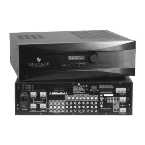
Page 8: Front Panel Guide
Front Panel Guide USB Mini B port Front Panel The port is used to setup, control or monitor the Solid Aluminium front Panel amplifi er. A USB mini B cable must be used when Infra-Red Receiver connecting to a PC Receiver for front panel IR control –... -
Page 9: Rear Panel Guide
Rear Panel Guide AC Inlet Input Terminals IEC socket Audio and Composite Video Source inputs. Speaker Terminals Expansion Bus Input Plug in terminal clamp connectors accept 1.5mm² Connects with another 450 series amplifi er’s (15 gauge) speaker wires expansion bus output – provides connection of source equipment audio, control and IR. -
Page 10: Typical System Confi Guration
Typical System Confi guration FIG 1... - Page 11 Typical System Confi guration – Continued Speakers Fig 1 depicts a typical confi guration where the 450 series amplifi er is providing audio into four listening Speakers in each zone are connected to the amplifi er by zones. “Home Run” speaker cables. Each zone consists of a room with a pair of speakers, Fig 1 depicts a powered subwoofer in the study.
-
Page 12: Controller Termination
Controller Termination RJ45 Pin Wire Colour Keypad function White/Orange +12V DC supply Orange supply White/Green output Blue White/Blue Data input Green supply White/Brown Brown Table 1 Orange & Green Orange & Green White/Blue White/Blue White/Green White/Green White/Orange White/Orange CAT5E cable CAT5E cable FIG 2 The recommended wiring and colour scheme is shown in Fig 2. -
Page 13: Advanced Ir Control
Advanced IR Control FIG 3 IR routing – discussed in Typical System confi guration” on page 11 is used to address centrally located source equipment. When multiple same brand / model source equipment is used steps must be taken to isolate the radiated IR from interfering with their discrete operation. - Page 14 Multiple 450 Series Amplifi er Stacks FIG 4 In large installations where multiple 450 series amplifi ers are required, the expansion bus may be used to convey inter-amplifi er control, source equipment audio and IR control. Fig 4 shows inter-connected amplifi ers using an expansion bus lead. The source equipment audio inputs must be plugged into the fi rst amplifi er where they are buffered and sent to the next amplifi er in the stack.
-
Page 15: Zone Linking
Zone Linking FIG 5 Zone linking is a useful feature for simplifying control in closely coupled rooms, where the rooms require different volume levels and ON /Off status, yet the same audio source. If for instance the Lounge and Study zones in the ‘Typical System Confi guration’ were always used together on the same source, then zone linking could be used to simplify the control of the two otherwise separate zones. -
Page 16: Automation
Automation FIG 6 Any amplifi er parameter is controllable using the serial RS232 interface. The RS232 protocol is outlined in the following section and encompasses both the amplifi er and connected keypads. The interface is bi-directional, allowing the amplifi er and network to be monitored. The RS232 port connection must be made using a ‘Null Modem’... -
Page 17: Rs232 Protocol
RS232 Protocol The RS232 serial port provides data acquisition and control of the 450 Series amplifi ers and networked keypads by a home automation system, or PC. The interconnecting cable must be ‘Null modem’: 9 pin female ‘D’ connectors at both ends (pin connections 2 and 3 swapped at one end) only RX, TX &... - Page 18 RS232 Protocol – Continued Data Command Content Standby 00 – Standby OFF 01 – Standby ON (01) 04 – Toggle 00 – Mute Mute (02) 01 – Un-mute 02 – Toggle Mute Source Selection 00 – S5 (03) 01 – S6 02 –...
- Page 19 RS232 Protocol – Continued Command Content Preset Selection All Zone function: Zone byte = FF (1E) 00 – Default : exit preset mode 01 – Force “Page Preset” 02 – Select Preset 1 03 – Select Preset 2 04 – Select Preset 3 05 –...
- Page 20 RS232 Protocol – Continued Keypad key codes A Keypad controller may be directed to emit its learnt IR commands via RS232 control. This is achieved by sending a ‘Cause key press on Keypad’ command “0B” followed by the zone, and the Keypad key code (data).
-
Page 21: Menu Navigation
Menu Navigation Front Panel user interface: The Axium 450 series amplifi er has a LCD display and multi-jog (Rotary Encoder with Push Select) for menu navigation. The menus are hierarchal providing access and control of all amplifi er functions. The user navigates through the menu using left / right multi jog rotations and pushes for selections or escapes. - Page 22 Select Room Select Room: Z4 Amp: Bedroom The selected device zone, zone number and room name (if named) are displayed. The Illuminated circle represents the selected device zone. The order – left to right – is the same as the front panel Zone power indicators –...
-
Page 23: System Setup
System Setup System Setup Set Clock The System Setup menu is entered by pushing and holding the Multi Jog for > 10 seconds. Rotating the Multi Jog displays the next System Setup function in the list: • Set Clock • Presets •... - Page 24 Menu Navigation – Continued Restore Defaults: Clears the amplifi er memory deleting Zone assignments, Room names, Zone Linking, Maximum Volume Limits, Bass, Treble & Balance adjustments, Loudness settings, Preset and Alarm clock and Preset programming. Select Yes to Restore Defaults. System Setup Are you sure? Restore Defaults...
-
Page 25: Main Window
Programming Using MC Overview MC is an amplifi er setup program. Full control and tracking of any 450 series amplifi er zone is provided. The program runs on PC’s running Win 2000 - Win XP operating systems, and communicates via either RS232 or USB. When a 450 series amplifi er is fi rst attached to a PC running MC the clock is automatically set to the PC’s current time, date and location. - Page 26 Programming Using MC – Continued Zone Select: To select the zone move the cursor over the zone tab’s down arrow and left click. A zone list window appears - make the selection with a left mouse click. Placing the cursor over the zone tab’s room description displays information about the amplifi er’s device ID / serial number.
- Page 27 Programming Using MC – Continued Volume Levels • The volume sliders may be changed either by left clicks above or below the displayed level, or by dragging the level down using a left click and hold. Note: If the preamplifi er is in ‘Tracking’ mode then changing one volume changes the other. Maximum Volume Limit •...
- Page 28 Programming Using MC – Continued Setup Window The window provides the means to control the occasionally used functions like bass, treble, amplifi er and preamplifi er balance and loudness. These are all adjusted using a left mouse click while above the button or slider. Note: The preamplifi er and amplifi er share the same bass &...
- Page 29 Programming Using MC – Continued Preset Setup Window Preset Programming Presets are all zone functions. There are six preset buttons – Preset 1 - Preset 6. These presets are stored in the amplifi er, and may be setup using the MC setup window. Left click over “Set up preset 1”...
- Page 30 Programming Using MC – Continued Alarm Clock programming An alarm clock event may be included in a preset. In the Preset Setup window left Click a spare “Set up preset” – for this example Preset 6 is selected. Left click the “Alarm Enable” in the Schedule panel. Select the required time and days that the Alarm is to operate and change all the required settings in MC’s main window i.e., which zones are ON, their volume and source selection etc.
- Page 31 Programming Using MC – Continued Source Control Alarm Clock programming Source Control Alarm Clock programming If an AX-KPB keypad is connected to the 450 series amplifi er then source If an AX-KPB keypad is connected to the 450 series amplifi er then source control can also be included in an Alarm preset.
-
Page 32: Specifi Cations
Specifi cations Amplifi er Section Rated Output Power (FTC) All Channels: 50 Watts minimum continuous power / channel, 8 ohm loads, 65 Watts continuous power / channel, 6 ohm loads, 2 Channels driven @ 1KHz, with a maximum harmonic distortion of 0.05% THD (Total Harmonic Distortion) 0.05% (Rated Power) Damping Factor...