Table of Contents
Advertisement
Quick Links
Advertisement
Table of Contents

Summary of Contents for Unique Klasse KUD-WG33S
-
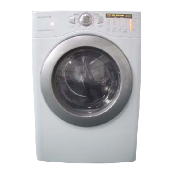
Page 1: Gas Dryer
Service Manual Gas Dryer Model : KUD-WG33S JUL. 2008... -
Page 2: Table Of Contents
Contents What is a Dryer? .....................2 Dryer Specification....................4 Operating Mechanism Diagram (Gas Type) ............5 Mechanism by Ass’y (Gas Type)................6 Parts List by Ass’y....................7 Procedure for Reversing the Door................18 PCB Function Specification...................19 Gas Dryer PCB Pin ....................31 Drum Dryer Troubleshooter ..................32 Gas Dryer Wiring Diagrams................33 Dryer Installation .. - Page 3 What is a Dryer? 1. What is a Dryer? A lifter, operated by a rotating drum, rolls laundry in the drum, and hot air heated by electricity (or gas) dries the laundry through time or sensor dry system (a temperature control system) under various conditions. 2.
- Page 4 3. Key Functions Time Dry • Adjust the length of time for drying. Sensor Dry • Automatically dry according to the types of laundry. Custom Program • Remember most-frequently-used drying course. Rack Dry • Dry sensitive fabric (e.g. sweaters, silk, lingerie) on the rack. Wrinkle Care •...
-
Page 5: Dryer Specification
Dryer Specification 1. Product Look Parts FRAME DOOR O PROTECTOR GLASS PANEL FRONT CABINET FRONT PLATE TOP CABINET BUTTON POWER BUTTON START BADGE KLASSE WINDOW COURSE BUTTON FUNCTION BUTTON OPTION WINDOW DISPLAY LESS TIME MORE TIME DECO COURSE BUTTON DIAL WINDOW FUNCTION Dimensions 27"... -
Page 6: Operating Mechanism Diagram (Gas Type)
Operating Mechanism Diagram (Gas Type) Electric Input Operating Mechanism • Controller operation • Operator/gas burner/air supplier/ventilator operation Program • Automatic operation of the controller • Drying by the automatic sensor 1. Controller lifter • MAIN PCB plate top • FRONT PCB •... - Page 7 Ensamble secadora de gas TAPA SUPERIOR PCB CONTROL ENSAMBLE GABINETE DRUM SUPORTE POSTERIOR PANEL F RONTAL DUCTO DE AIRE SOPORTE TAMBOR FRONTAL CABINETE FRONTAL QUEMADOR ENSAMBLE TAMBOR...
-
Page 8: Parts List By Ass'y
Parts List by Ass’y 1. DRYER CBINET ASS'Y... - Page 9 Part Name Part Code Description Qtt'y Remark CABINET(ELECTRIC) 3610812350 SGCC 0.8T CABINET(GAS) 3610812360 SGCC 0.8T C01-1 FRAME TOP L 3612206500 SGCC 1.6T 1 PIECE SVC PART C01-2 FRAME TOP R 3612206600 SGCC 1.6T C01-3 BASE UNDER 3610392900 SGCD 0.8T LOCK HARNESS M 3612207900 NYLON FRAME UPPER...
- Page 10 2. DRYER MOTOR ASS'Y Part Name Part Code Description Qtt'y Remark BRACKET MOTOR 3610608500 SGCC 2.0T MOTOR DRYER 36189L5D00 AC 120V 60Hz CLAMP MOTOR 3611206000 SK5 0.7T BRACKET IDLER AS 3610609100 DWR-WE31 SPRING IDLER 3615115500 HSW3 SPECIAL BOLT 3616039000 S18A M6x10(FLANGE) SWITCH MICRO 3619047500 UL.
- Page 11 3. Gas Type Part Name Part Code Description Qtt'y Remark VALVE AS 3615417200 DC12V,130mA 0.5Psi 3615417300 DC12V,130mA 0.5Psi SCREW TAPPING T1 M4*8 For fixing G01 & G03 GUIDE BUNNER 3612511100 SGCC 1.0T MIXING VENTURI AS 3612209200 VENTURI AS+ FLAME DAMPER WELDING(SPOT) SCREW TAPPING M4*8, T1...
- Page 12 4. INLETDUCT ASS'Y 4-1. Electric Type 4-2. Gas Type Part Name Part Code Description Qtt’y Remark DUCT INLET REAR 3617510200 ALCOSTAR 0.6t ELECTRIC TYPE 3617510210 ALCOSTAR 0.6t GAS TYPE DUCT INLET FRONT 3617510300 ALCOSTAR 0.6t ELECTRIC TYPE 3617510310 ALCOSTAR 0.6t GAS TYPE HEATER AS 3612802500 240V 5,400W...
- Page 13 5. SUPPORT DRUM REAR ASS'Y Part Name Part Code Description Qtt'y Remark SUPPORT DRUM REAR 3615304500 SUS304 0.8t BRACKET SUP.R-SIDE 3610608810 SGCC 1.0t BRACKET SUP.R-UPPER 3610608910 SGCC 1.0t SCREW TAPPING 7122401411 T2 TRS 4x14 MFZN For fixing bracket supp.up & side ROLLER AS 3614714400 ASSY...
- Page 14 6. SUPPORT DRUM FRONT ASS'Y Part Name Part Code Description Qtt'y Remark SUP. DRUM F 3615304600 SECD 0.8T HOUSING LAMP 3613053400 PP(Heat Resisting) SOCKET LAMP 3613053300 14 BASE LEAD WIRE TYPE LAMP 3613625400 AC 125V 15W WINDOW LAMP 3615505100 ABS(Transparent) SCREW TAPPING 7112401208 T1 TRS 4x12 SUS...
- Page 15 7. DRUM ASS'Y Part Name Part Code Description Qtt'y Remark DRUM 3617010000 SUS 0.5t ø660 x 570 LIFTER 361A401000 Heat resisting PP SCREW TAPPING 7122502008 T2 TRS 5x20 SUS For fixing lifter SEAL DRUM AS 3614010600 Pelt+ Synthetic leather PAD DRUM 3614111110 BUTYL V-BELT...
- Page 16 8. DOOR ASS'Y Part Name Part Code Description Qtt'y Remark FRAME DOOR I 3612208000 Heat resisting PP GLASS DOOR 36117ABR00 Glass or PROTECTOR GLASS 3618304300 Transparent ABS HINGE DOOR 3612903600 Zn-Dc Zn Plated CAP HINGE DOOR 3610916500 FRAME DOOR O 3612208110 GASKET DOOR 3612323000...
- Page 17 9. PLATE T AS Part Name Part Code Description Qtt'y Remarks PLATE TOP 3614533010 SECD 1.2T PLATE SUPPORTER AS 3615304100 ABS + EPDM SCREW TAPPING 7122401411 T2S TRS 4x14 MFZN...
- Page 18 10. CABINET FRONT ASS'Y Part Name Part Code Description Qtt'y Remark CABINET-F 3610812500 SGCD 0.8t GASKET CABINET F 3612323300 EPDM 460x15x4.0T SUPPORTER HINGE 3615304400 SGCC 2.0t DOOR LOCK AS 3613802500 SCREW TAPPING 7122401409 T2S TRS 4x14 SUS430 For fixing door lock as SWITCH DOOR 3619047700 125V/5A...
- Page 19 11. PANEL F ASS'Y Part Name Part Code Description Qtt'y Remark PANEL-F 3614287000 ABS + SILK print BUTTON POWER 3616635900 BUTTON START 3616636000 SPRING BUTTON 3615115700 SUS304 DECO COURSE 3611685400 WINDOW COURSE 3615504800 Transparent ABS(TR558) WINDOW DISPLAY 3615504900 Transparent ABS(UT-0510) BUTTON FUNCTION 3616636100 WINDOW FUNCTION...
- Page 20 12. Procedimiento para invertir la puerta. La puerta de la secadora puede ser instalada para abrir a derecha o a la izquierda. Siga las instrucciones para cambiar la dirección en que abre la puerta. Nota: La puerta y el seguro deben de estar alineados al centro cuando se cierra la puerta.
-
Page 21: Pcb Function Specification
PCB Function Specification 1. 27-Inch Dryer PCB Function Specification Comprehensive function specification of the unit including operation of a 27-inch dryer by drying courses and drying functions, control of electronic devices by PCB, operation by S/W, test function, error mode, and so on. Index Descriptions Miscellaneous... - Page 22 2.Descripción de cursos 2-1. Ciclos de secado 1) Cursos por Sensor SECADO POR SENSOR Normal Cotton/Towels HEAVY DUTY BULKY/LARGE Very Dry 1:01 1:05 1:05 1:10 More Dry 1:02 1:00 NIVEL DE Normal SECADO Less Dry Damp Dry Nivel por omisión Normal Normal Normal...
- Page 23 2) Curso de secado manual CICLOS SECADO MANUAL SPEED DRY FRESHEN UP AIR DRY WARM-UP TEMP Time CONTROL Temp Default High Mid high Medium DRY LEVEL TEMP Ultra Low ~ High Ultra Low ~ High Ultra Low ~ High A. Sólo temp. es seleccionada en los cursos manuales. B.
- Page 24 2-2. Operation 1) Overview Different operation processes are applied to Sensor Dry Course and Manual Dry Course. Sensor Dry Course judges the condition of laundry with humidity/temperature sensors so as to decide appropriate dry level. Manual Dry Course dries laundry as per temperature conditions set by an operator. 2) Process of Sensor Dry Course A.
- Page 25 3) Process of Manual Dry Course A. Power Button On “_ _ _” is displayed at 18:88 LED. “Check Filter” of Custom LED goes on and off before you press Start Button. “High” of initial Beeper goes on and the previous Beeper value is displayed when you switch on the power.
- Page 26 2-3. Operación del Sensor 1) Operation of Heater - Electric Type On/Off goes on according to temperatures set or measured by the sensor. Regardless of the control by the microcomputer, however, the heater may go off if a temperature reaches Thermostat Off Temperature as per outlet conditions.
- Page 27 2-4. Operation of Buttons 1) Power A. The electric power switch turns on/off the display. B. Automatic switch off function 1 Power is immediately switched off after an operation is done. 2 Power is switched off after 10 minutes if no button is selected while power is on. C.
- Page 28 4) Control de Temperatura A. Presionando este boton la scuencia en display es la siguiente. Medium - Mid High - High - Ultra Low - Low - Medium B. Nivel seleccionado / temperatura de corte (termostato del ventilador) Target Temperatures Level Heater-Off(°C) Heater-On(°C)
- Page 29 8) Less Time A. Pressing this button decreases time by a minute. B. The time decreases up to 00:15 (minutes) C. You can change time in Manual Dry Course and Time Selection. Also Wrinkle Care can be selected/cancelled. 9) Custom Program A.
- Page 30 2-5. Option Custom Wrinkle Anti Damp Dry Level More Time Less Time Rack Dry Program Care Bacterial Beep Bulky/Large Heavy Duty Cotton/Towls Normal Perm Press Delicates Ultra Delicates Speed Dry Freshen Up Air Dry A. If you select Rack Dry, the previous course and operation goes off. B.
- Page 31 2-6. Error Mode 1) H1 error - Error del sensor de humedad 1 Ocurre si el sensor de humedad está en corto (indica un valor menor a 24) 2 La señal sonora indica el error, cada 10 min. por 10 seg. 3 El error en el display se borra al apagar la secadora.
- Page 32 2-7. Modo de prueba 1) MODO DE PRUEBA PCB A. Prueba PCB: presione simultaneamente 'Encendido' , Nivel de secado' y Control de temperatura. B. Secuencia de Operación: Revise la secuencia presionado 'Inicio'. Operación Load Time (Sec) DISPLAY Tipo Encienden todos los LED´s LED´s Compartido secadora.
-
Page 33: Gas Dryer Pcb Pin
4. GAS DRYER PCB PIN... - Page 34 Guía de fallas ENCENDIDO / RUIDO Problema Síntoma Causa Solución Cable de Falla en cable de alimentación Revise suministro de Poder Fusible de servicio desconectado electricidad Cable de poder dañado Cambie el cable Problema de partes Terminal de controlador desconectada Revise conexión Eléctricas de Terminal desconectada del...
- Page 35 2. DIAGRAMA SECADORA DE GAS...
-
Page 36: Dryer Installation
Dryer Installation 1. Installation Order 1 Place the dryer on the flat ground. Keep the unit at least 12 inch away from the wall. 2 Check the 4 legs and the gap between the unit and floor. The dryer should stand stably when you try to move the unit to the left or right. -
Page 37: Dryer Service Notices
Dryer Service Notices Service Parts Notices Replacing the Humidity sensor Be careful of the terminal connection humidity sensor Be careful of loose attachment Replacing/fixing panel f assy PCB/BUTTON/HARNESS Be sure that the panel f assy does not interfere in the drum after the service Replacing the lifter LIFTER... -
Page 38: Electric Parts List - Gas Clothes Dryer
Electric Parts List - Gas Clothes Dryer Part Name Part Code Type No Rating Main function Lamp Holder: 4000 series 75W, 125V Lamp AS 3612625300 Power is applied to the lamp to turn up the Lamp Base: E12 15W, 125V light in the drum when the door is opened. -
Page 39: Thermostat Fan
Termostato Ventilador Part Code : 3619047900 1. Function • This is a bimetal-type switch which protects the clothes from damage by overheating. • If the exaust air is too hot, this thermostat stops the motor and after the air is cooled down, it restarts the motor. - Page 40 Lámpara Part Code : 3612625300 1. Function • This is a lamp assembled with its bracket and window. • If the user opens the door, the door switch gives electric power to this lamp and it turns on. 2. Especificación •...
- Page 41 Switch de Puerta Part Code : 3619047700 1. Function • This is a switch that checks whether the door is open or closed. • If the user opens the door, this switch disconnects power supply to the motor and turns the lamp on. •...
- Page 42 Switch de Banda Part Code : 3619047500 1. Function • The switch cuts the power supply to the motor when a belt is broken. • The switch is on when the belt has adequate tension but off when the belt gets loosened or broken, blocking the power supply to the motor.
- Page 43 Belt Switch 7 Remove wires and 2 screws that fix the switch. 8 Assemble the parts in reverse order.
-
Page 44: Thermistor Fan
Thermistor Ventilador Part Code : 361AAAAC20 1. Function • The fan senses the temperature of exhaust air. • The higher the temperature is, the smaller the resistance is. 2. Especificación • Características temperatura-resistencia del Thermistor. a 90°C : R = 4.43 kΩ a 40°C : R = 26.07 kΩ... -
Page 45: Motor Dryer
Motor Dryer Part Code : 36189L5D00 1. Function • The motor rotates the drum using the belt as well as the fan to expel wet air. • This is a shunt AC motor. When the motor begins to run, a centrifugal switch shorts out the operation coil. - Page 46 5 Drum Ass'y remove 7 Remove the cover fan and 3 screws. 6 Cover Fan remove Loosen the 3 screws as indicated with a circle. 8 Remove the 4 screws and the motor ass’y. Loosen the 3 screws as indicated with a circle. 9 Remove wires and 2 clamps that fix the motor bearing to detach the motor.
- Page 47 Ignitor Part Code : 36189L5800 1. Function • Igniter for fuel gas ignition. • Igniter heats up quickly when power is supplied. If fuel gas is injected to the surrounding area of igniter, gas is ignited by the heat of igniter. 2.
- Page 48 Sensor de Flama Part Code : 3614825700 1. Function • Sensor flame is the switch that operates by detecting fuel gas ignition or heating of igniter. • Contact point is opened when sufficient radiant heat is detected through the transparent window at the bottom of sensor. •...
- Page 49 Termostato Limite Alto Part Code : 3619047610 1. Function • This is a bimetal-type switch which stops the burner overheating. • If the burner is too hot, this thermostat shuts off the gas valves and after the burner is cooled down, it allows the gas valves to operate. 2.
-
Page 50: Thermostat Cut-Out
Termostato de Corte Part Code : 3619047810 1. Function • This is a bimetal-type switch which protects the burner from overheating. • If the burner is overheated abnormally, this thermostat cuts off the gas valves PERMANENTLY. • Note that this thermostat is MANUALLY-RESETTABLE; by pressing the knob on the top, this part is returned to reusable state. -
Page 51: Valve Gas
Válvula de Gas Part Code : 3615417200, -7300 1. Function • Valve gas AS supplies or blocks off fuel gas. • 2 valves are horizontally connected to safely block off gas leakage. • Each valve is solenoid value. Gas passed through this valve is injected after being stabilized to the prescribed output pressure in regulator. - Page 52 MÉTODO DE DESENSAMBLE PANEL FRONTAL 1. Quite el tapón izquierdo y retire el tornillo. 2. Separe el panel frontal, cuide no dañar los ganchos internos. Empuje con cuidado hacia arriba, presionando hacia dentro TAPA SUPERIOR 1. Retire 3 tornillos del frente. 2.
- Page 53 GABINETE FRONTAL 1. Retire 4 tornillos superiores. 2. Saque el filtro. 3. Retire 3 tornillos. 4. Levante el gabinete en dirección de la flecha, jalando hacia el frente. 5. Desconecte el switch de la puerta.
- Page 54 MARCO SUPERIOR 1. Retire 1 tornillo de cada lado del marco. 2. Retire los tornillos superiores. 3. Separe el marco después de quitar el arnés. CONECTOR DE LÁMPARA, PCB Y SENSOR 1. Separe conector de lámpara. 2. Separe conectores de PCB. 3.
- Page 55 PCB MAIN 1. Retire 2 tornillos. 3. Jale hacia arriba, libere los ganchos de la PCB. DUCTO DE SALIDA 1. Retire 2 tornillos de cada lado. 2. Retire 1 tornillo de abajo. 3. Retire el ducto en dirección de las flechas.
- Page 56 TAPA POSTERIOR 1. Retire 10 tornillos. SOPORTE DEL TAMBOR TRASERO 1. Retire terminales del calefactor (sólo secadora eléctrica). 2. Retire 7 tornillos. 3. Retire soporte en dirección de la flecha.
- Page 57 CABLEADO Y MOTOR 1. Separación del sensor de temperatura : Desconecte. Retire el tornillo. 2. Separación del termostato: Desconecte. Retire 2 tornillos. 3. Desconecte micro switch del motor 4. Retire conector del motor .
- Page 58 BLOCK DE TERMINALES 1. Remove cover terminal. 2. Remove 3 screws. sólo secadora eléctrica...
- Page 59 ENSAMBLE MOTOR 1. Retire 6 tronillos y separe el motor. 2. Desensamble ventilador: Remueva 2 tornillos. 3. Retire la tuerca (cuerda izq.) y separe el ventilador del motor.
- Page 60 4. Desensamble caja ventilador: Retire 3 tornillos. 5. Desensamble base del motor: Retire 2 abrazaderas (1 cada extremo) LÁMPARA 1. Retire 1 tornillo.
- Page 61 CAJA FILTRO Y SENSOR DE HUMEDAD 1. Caja filtro: Retire 2 tornillos. 2.Desconecte Sensor Humedad 3. Remueva Sensor.
- Page 62 PUERTA 1. Separación de bisagra y soporte tambor frontal: Retire 2 tornillos. 2. Retire 13 tornillos 3. Seguro de puerta: Retire 2 tornillos y quite el seguro de puerta.
- Page 63 4. Switch de Puerta: Presione los seguros y empuje hacia el frente.
Need help?
Do you have a question about the KUD-WG33S and is the answer not in the manual?
Questions and answers