
Subscribe to Our Youtube Channel
Summary of Contents for Gilat SkyEdge IIc
- Page 1 CPE Installation and Pointing User Guide July 2013 Revision Number 1.1 Document Number: DC-002966(D)
- Page 2 This document contains information proprietary to Gilat Satellite Networks Ltd. and its affiliates and may not be reproduced in whole or in part without the express written consent of Gilat Satellite Networks Ltd. The disclosure by Gilat Satellite Networks Ltd. of information contained herein does not constitute any license or authorization to use or disclose the...
-
Page 3: Table Of Contents
Contents Chapter 1: Introduction ........................ 5 Overview ........................5 Document Conventions ....................6 Terms of Direction ......................6 How to Use This Manual and Kit..................7 Chapter 2: Safety .......................... 8 Warnings ........................8 Cautions ......................... 9 Notices ........................... 9 Chapter 3: Box Contents ...................... - Page 4 Chapter 5: Modem Configuration....................43 Choosing Installation Time ................... 43 Installing and Connecting Modem ................. 43 Connecting RF Cables to Modem .................... 44 Connecting Modem to Power Adapter ..................45 Connecting Modem to PC ......................45 Supported Operating Systems and Browsers ................45 Configuring Computer ......................
- Page 5 Overview Can I add a wireless router or an Ethernet switch behind the modem?......83 Can weather conditions affect modem reception? ............83 Are any Internet ports/addresses blocked? ..............84 Can I watch movies online? ..................84 Do I need authorization to install satellite dish? ............84 What do I do if I cannot find installation CD/equipment, etc.? ........
-
Page 7: Chapter 1: Introduction
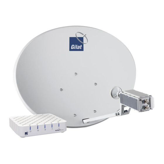
...................... Overview Congratulations on purchasing a Gilat’s broadband Internet-over-Ka satellite kit. By following a few simple steps, you will assemble a satellite dish and point it to a satellite orbiting 36,000 km above earth. Once the dish has been pointed successfully, the modem will log on to the system. -
Page 8: Document Conventions
Document Conventions Introduction Document Conventions This symbol means "Danger!" It is used to describe a situation that can cause bodily injury. Before working with any equipment, know the hazards involved and how to prevent accidents. This symbol means "Be careful!" In this situation, damage can be caused to equipment or data can be lost. -
Page 9: How To Use This Manual And Kit
How to Use This Manual and Kit How to Use This Manual and Kit We recommend using the kit in the following order: Read the manual Watch the installation video CD Start the installation July, 2013 Proprietary and Confidential... -
Page 10: Chapter 2: Safety
Warnings Safety Chapter 2: Safety Warnings Please read all operating instructions and safety precautions in this manual prior to any installation works. Install the modem, dish, and wiring according to national and local regulations issued by authorities. Mount the dish on a properly anchored pole or bracket, capable of bearing the dish weight and wind load. -
Page 11: Cautions
Cautions Different types of power cords may be used for connections to the electrical outlet. Use only a main line cord that complies with safety requirements of the country of use. Do not use power cord if damaged. Connect the power cord to a properly grounded three-prong alternating current outlet only. -
Page 13: Chapter 3: Box Contents
Chapter 3: Box Contents In This Section What's in the Box ........................... Packing List ............................ What's Not in the Box ........................What's in the Box It is important to open the box in a suitable location to ensure the modem is not exposed to excessive humidity and/or extreme temperatures. - Page 14 What's in the Box Box Contents Figure 4: Box Contents The box must contain the following kit components: Description Az/El with clamps Back bracket Skew plate Reflector Boom arm Transceiver bracket Transceiver RF cables and F-connectors Grounding cable bag Modem box TV Receiver Bracket/Holder Kit (optional) Hardware Bag Documentation Bag...
-
Page 15: Packing List
Packing List If something is missing/damaged/wrong, contact your supplier. 4. Set aside the modem box for later use. Figure 5: Modem Box 5. Put the rest of the components back into the kit box to make it easy to transport to the dish installation location. - Page 16 Packing List Box Contents Item Quantity Image Reflector Boom arm Transceiver bracket Back bracket CPE Installation and Pointing Proprietary and Confidential...
- Page 17 Packing List Item Quantity Image Az/El (assembled - with pole clamps) Skew plate Hardware bag 1 set - see below Documentation 1 set - see below Modem 1 set - see packaging box below Transceiver 1 set - see packaging box below July, 2013 Proprietary and Confidential...
-
Page 18: Modem Packaging Box
Packing List Box Contents Modem Packaging Box The box includes the following items: Item Quantity SkyEdge II-c Aries modem Power adapter Power cable LAN Cable F-connector Figure 6: Modem Box Transceiver Packaging Box The box includes the following items: Item Quantity Transceiver with Feed and Polarizer Grounding screw... -
Page 19: Hardware Bag
Packing List Figure 7: Transceiver Box Content Hardware Bag The bag includes the following items: Dish Assembly Kit Item Description Quantity Bolt M8X20 Carriage bolt - short neck, M8x1.25mm thread Spring Washer for 8-mm bolt Flat Washer for 8-mm bolt Hex M8X1.25 Mounting Kit Item... -
Page 20: Documentation Bag
What's Not in the Box Box Contents Grounding Kit Item Description Quantity Screw Hex head tapping screw, 1/4-20 x 5/8 Washer Ext tooth lock washer 1/4" Wire Grounding wire Documentation Bag The box includes the following items: Item Quantity Quick Guide What's Not in the Box What you need to provide: A Leveled Pole... -
Page 21: Pointing Data
What's Not in the Box Pointing Data The invoice contains important data necessary for successful installation. Do not start the installation unless you have the invoice with all the data (see below). Pointing data (appears in the invoice): Satellite name ... -
Page 23: Chapter 4: Installing Equipment
Chapter 4: Installing Equipment In This Section Selecting Dish Location........................Installing Pole ..........................Installing Dish ..........................Selecting Dish Location Determine the suitable location for your satellite dish. Selecting a suitable outdoor location with a clear view towards the satellite is very important: obstructions (e.g., buildings or trees) may affect the signal strength. -
Page 24: Installing Pole
Installing Pole Installing Equipment Figure 9: Unsuitable Location 2 For information on how to select dish location using a smartphone application, refer to Dish Pointing Smartphone Applications (on page 65). Installing Pole When installing the pole for the dish, follow these guidelines: The pole diameter must be between 45 and 70 mm. -
Page 25: Assembling Back Bracket With Az/El
Installing Dish Figure 10: Modem Box Assembling Back Bracket with Az/El To assemble the back bracket on the Az/El: 1. Place the Az/El, clamps down, on an even surface so that its elevation bracket surface faces upwards. July, 2013 Proprietary and Confidential... -
Page 26: Mounting Az/El On Pole
Installing Dish Installing Equipment Figure 11: Assembling the Back Bracket with the Az/El 2. Position the back bracket with its rear surface to the Az/El. 3. Apply the skew plate to the back bracket with the arrow marking facing forward. 4. - Page 27 Installing Dish Figure 12: Clamps Released 3. Place the Az/El on the pole. 4. Reposition the clamps on the bolts. To ensure a sturdy mount, make sure that the clamp has been shifted in the direction of its open end as far as possible. 5.
-
Page 28: Setting Nominal Elevation
Installing Dish Installing Equipment Figure 13: Tightening the Nuts Tips: It is important to partially tighten the nuts to prevent the assembly from sliding down the pole under its own weight, but leave some leeway to allow the rotation of the assembly around the pole with just a moderate effort during the pointing procedure. - Page 29 Installing Dish Figure 14: Retention Nuts 2. Verify that the two nuts retaining the Az/El horizontally movable part (marked with smaller circles) are loose. 3. Rotate the elevation screw to set the nominal elevation value as indicated in the invoice. Figure 15: Elevation Screw July, 2013 Proprietary and Confidential...
-
Page 30: Mounting Reflector
Installing Dish Installing Equipment The Az/El unit is supplied preset to 20 degrees elevation (see Figure above). The bars of the elevation scale have a 2-degree resolution; smaller markings in between provide a 1-degree grid. Mounting Reflector To mount the reflector: 1. - Page 31 Installing Dish Figure 17: Reflector - Uppermost Hole 4. Put a flat washer and a spring washer on the bolt. 5. Thread a nut 2-3 threads onto the bolt. Figure 18: Dish above U-Slot 6. Bring the reflector in contact with the back bracket and slide it down so that the bolt would enter the U-slot of the back bracket to establish the initial positioning.
- Page 32 Installing Dish Installing Equipment Figure 19: Nut Threaded Halfway on Bolt 7. Insert the remaining four bolts to attach the reflector to the back bracket. Figure 20: Reflector with Screws Inserted 8. On each bolt, place a flat washer, then a spring washer, then a nut. CPE Installation and Pointing Proprietary and Confidential...
-
Page 33: Attaching Boom Arm To Back Bracket
Installing Dish Figure 21: Reflector Attached to Back Bracket 9. Tighten all the nuts by hand first; complete the tightening of all the nuts with a spanner/ratchet. Attaching Boom Arm to Back Bracket To attach the boom arm to the back bracket: 1. -
Page 34: Assembling Transceiver Bracket And Transceiver
Installing Dish Installing Equipment Figure 23: Attaching Boom Arm Assembling Transceiver Bracket and Transceiver To assemble the transceiver bracket and the transceiver: 1. Apply the bracket onto the transceiver as shown in the Figure below. Figure 24: Assembling Transceiver on Bracket 2. -
Page 35: Assembling Transceiver Bracket On Boom Arm
Installing Dish 3. Insert the four bolts with spring washers to secure the transceiver on the transceiver arm. 4. Tighten the four bolts with the Allen key (supplied). Assembling Transceiver Bracket on Boom Arm To assemble the transceiver bracket on the boom arm: 1. -
Page 36: Threading Rf Cables Through The Boom
Installing Dish Installing Equipment Figure 26: Attaching Bracket to Arm If you have purchased the optional TV Reception kit, please refer to (Optional) TV Reception Kit (on page 78). Threading RF Cables Through the Boom Each coaxial cable is equipped with a connector on the outdoor end. The indoor end of the cable has no connectors attached. -
Page 37: Connecting Cables To Transceiver
Installing Dish Connecting Cables to Transceiver To connect the cables to the transceiver: 1. Screw the male F-connectors of the RF cables onto the corresponding female RF-connectors of the transceiver (Rx to Rx, and Tx to Tx) leaving a loop of cable (excess length) as shown in the Figure below. -
Page 38: Setting Nominal Skew
Installing Dish Installing Equipment 2. Connect the other end of the equipotential bonding cable to the pole clamp using the screw provided. Figure 28: Grounding BUC to Pole Clamp 3. Ground the pole supporting the dish assembly according to local regulations. Grounding can be done by attaching a down-conductor to the grounding screw of the back bracket (as shown in the image above) with a 6.5mm ring-terminal (not provided with this kit). -
Page 39: Setting Nominal Azimuth
Installing Dish Figure 29: Skew Scale 2. Tighten the four nuts holding the Az/EL-skew plate assembly together. Setting Nominal Azimuth At this stage, the bolts of the clamps should be partially tightened so that the Az/El is flush against the pole yet loose enough to allow it to rotate smoothly around the pole. - Page 40 Installing Dish Installing Equipment Figure 30: Azimuth Fine-Tuning Grid 2. Using a compass, determine the direction to point the dish according to the azimuth value provided in the invoice. 3. Rotate the dish assembly around the pole so as to point its front surface in the direction determined.
- Page 41 Installing Dish Figure 31: Elevation Offset Arrow If the pole is not ideally vertical, you will notice the offset on the offset scale (see the Figure below). Keep in mind that the bars of the elevation scale have a 2-degree resolution; smaller markings in between provide a 1-degree grid.
-
Page 42: Threading The Cables Into House
Installing Dish Installing Equipment Figure 32: Elevation Offset Scale 6. If a non-zero offset value is determined, adjust the position of the dish accordingly: for positive offset, increase the elevation (e.g., the invoice indicates 33 degrees elevation, and the elevation offset scale shows +1 degree; to compensate for the pole deviation, set the elevation to 34 degrees). - Page 43 Installing Dish Shortening the cables must be performed carefully: they are supplied with Tx and Rx stickers; cutting off the excess length of both cables together will make it impossible to determine which cable is which. You need to cut one cable first, and mark it (Rx or Tx, depending on which cable you are cutting off) with a permanent marker or a sticker to ensure that after cutting off the other cable, you will be able to determine which cable is which.
- Page 44 Installing Dish Installing Equipment Figure 33: Connector Assembled on Cable 7. Repeat this procedure assembling the other cable and F-connector. CPE Installation and Pointing Proprietary and Confidential...
-
Page 45: Chapter 5: Modem Configuration
Chapter 5: Modem Configuration In This Section Choosing Installation Time ......................Installing and Connecting Modem ....................Choosing Installation Time Service is available 24/7; therefore, installation can be performed anytime. For safety reasons, it is advisable to install the dish during the day. Initial pointing must be performed under clear sky condition to guarantee accurate pointing: pointing in rainy, cloudy, or windy weather can interfere with the stability of indicators. -
Page 46: Connecting Rf Cables To Modem
Installing and Connecting Modem Modem Configuration Figure 34: Unpacking Connecting RF Cables to Modem To connect the RF cables to the modem: 1. Screw the male cable F-connector marked Rx on the RF IN female connector on the modem (see arrow 1 in the Figure below). Figure 35: RF Connections 2. -
Page 47: Connecting Modem To Power Adapter
Installing and Connecting Modem Connecting Modem to Power Adapter To power up the modem: 1. Connect the power adapter provided in the kit to the modem. 2. Connect the power adapter to a wall outlet. The Power LED goes On. The modem performs a quick Power-On Self-Test (POST): the LEDs blink in a rapid succession. -
Page 48: Configuring Computer
Installing and Connecting Modem Modem Configuration Other OSs and browsers may work equally well, but have not been tested. You may use them at your own discretion. Configuring Computer Before configuring the modem, you need to verify that your computer is configured properly: 1. - Page 49 Installing and Connecting Modem Figure 37: Win7 DHCP 1 3. In the left panel of the Network and Sharing Center page, click Change adapter settings. Available LAN adapters are displayed. Figure 38: Win7 DHCP 2 4. Right-click the desired LAN adapter and select Properties. LAN Adapter properties box is displayed.
- Page 50 Installing and Connecting Modem Modem Configuration Figure 39: Win7 DHCP 3 5. Double-click Internet Protocol Version 4 (TCP/IPv4). TCP/IPv4 box is displayed. CPE Installation and Pointing Proprietary and Confidential...
- Page 51 Installing and Connecting Modem Figure 40: Win7 DHCP 4 6. Verify that Obtain an IP address automatically and Obtain DNS server address automatically are selected (if not, select), and click OK. Disabling Proxy Server Connection To disable a proxy server connection option: 1.
- Page 52 Installing and Connecting Modem Modem Configuration Figure 41: Disabling Proxy 1 2. Click LAN settings and verify that the Use a proxy server for your LAN checkbox is not selected. CPE Installation and Pointing Proprietary and Confidential...
- Page 53 Installing and Connecting Modem Figure 42: Disabling Proxy 2 3. Click OK to save the configuration. The dialog box is no longer displayed. 4. In the Internet Options box, click OK to close the Internet Options dialog box. MacOS Enabling DHCP To enable DHCP on the LAN adapter: 1.
-
Page 54: Entering Installation Parameters
Installing and Connecting Modem Modem Configuration 8. Click OK to confirm. 9. Click Apply. Entering Installation Parameters Do not start the installation until you verify that you have the Location Code and the RF Cluster Code (see the invoice). Without these parameters, you cannot successfully complete the modem configuration procedure. -
Page 55: Dish Pointing Preparation
Installing and Connecting Modem Language can be changed at any step. 4. Enter the location and the RF cluster codes, and click Next. The Dish Pointing page is displayed. Continue to the next section - Dish Pointing Preparation (on page 53). Dish Pointing Preparation To prepare the modem for dish pointing: 1. -
Page 56: Dish Pointing
Installing and Connecting Modem Modem Configuration Figure 45: Dish Pointing Preparation Page 2 3. The modem is ready to respond to the signal power fluctuations that will occur while you are pointing the dish. If nominal azimuth happens to be set accurately, the above screen may look slightly differently - showing that the signal is locked. -
Page 57: Coarse Pointing
Installing and Connecting Modem LockLowSNR LockMedSNR LockMaxSNR Peak – At any given time during the pointing there is a maximum reception level registered. This level will gradually increase as the pointing progresses. The peak continuous tone is coupled to the maximum reception level. Transition2Searching - if the Locked state is lost during the pointing, there will be a ... - Page 58 Installing and Connecting Modem Modem Configuration Abort tone will be heard if the kit installed is not compatible with the RF cluster code entered. Stop the installation and contact the Help Desk. Typically the initial nominal elevation setting should be sufficient for locking - but not the azimuth setting.
- Page 59 Installing and Connecting Modem Figure 47: Tightening the Nuts Tightening the nuts, the way it is described above is not mandatory, but it is recommended. Tightening the nuts in a different way may cause a change in the assembly position to the extent that the actual elevation and azimuth values will considerably differ from the nominal values.
-
Page 60: Fine Pointing
Installing and Connecting Modem Modem Configuration Once you tighten the nuts, the settings may change; consequently, the audio tones might change. This is the expected normal mode of operation. Fine Pointing The process is completed by fine-tuning the dish position using the built-in tuning tool until the strongest signal is obtained. - Page 61 Installing and Connecting Modem If the continuous tone position is not achieved, stop at the highest-pitch staggering tone (which indicates the strongest signal available) 4. Using a spanner/ratchet, rotate the elevation screw to change the elevation settings in either direction until the audio tone drops in pitch and stagger rate. Reverse the direction until a continuous tone position is achieved.
-
Page 62: Modem Installation
Installing and Connecting Modem Modem Configuration Figure 50: Nuts to Be Tightened 7. Apply light pressure on the side and top of the assembly until the tone changes to a staggering tone. Verify that once you let go, the tone returns to peak tone. 8. - Page 63 Installing and Connecting Modem Figure 51: Locked on Satellite 2. A reminder is displayed. July, 2013 Proprietary and Confidential...
- Page 64 Installing and Connecting Modem Modem Configuration Figure 52: Reminder 3. Click OK to start modem installation if you have tightened the bolts. 4. A 5-step modem installation process starts. You do not need to do anything: just follow the steps to verify that each one of them is completed successfully: a.
- Page 65 Installing and Connecting Modem Figure 53: Installation Complete box 5. Click Finish to complete the installation. The Home Page containing the system general information is displayed. Figure 54: Modem Installation - Final Screen July, 2013 Proprietary and Confidential...
-
Page 66: Dish Repointing
(in case the difference between the current value and the maximum achieved value is larger than expected) 6. This step completes the Gilat CPE installation. The user can start browsing the Internet. Dish Repointing If you ever need to repoint the dish, remember to loosen the azimuth and elevation fastening bolts. -
Page 67: Appendix A: Dish Pointing Smartphone Applications
Appendix A: Dish Pointing Smartphone Applications Satellite finder/dish pointing applications that run on a smartphone allow interposition of the projection of satellite positions on the sky on the actual view via the viewfinder of the built-in camera, based on Augmented Reality. To determine a suitable location using a smartphone: 1. -
Page 69: Appendix B: System Monitoring
Appendix B: System Monitoring In This Section Status ............................. Information ............................. Diagnostics ............................. Technician ............................Status This page allows you to check the general status of your modem. The message you expect to be displayed is Your modem is working properly! In case of malfunction, you may encounter other messages displayed. -
Page 70: Cpe Self-Test
Figure 55: Installation Log CPE Self-Test Self-test is a utility that allows testing modem connectivity, DNS resolution, and upload/download speed after temporarily disconnecting it from the computer (without physically disconnecting the LAN cable). This is done to separate modem-generated errors from issues caused by the computer connected to it. Figure 56: Self-Test CPE Installation and Pointing Proprietary and Confidential... - Page 71 Diagnostics To run the modem self-test: 1. Click on Diagnostics 2. (Optional) Select the Speed Test checkbox 3. Click Run Test The results of the self-test are displayed. Figure 57: Self-Test Results 4. To view detailed information, click View advanced information. July, 2013 Proprietary and Confidential...
-
Page 72: Technician
Figure 58: Test Advanced Information To view the results of the last test, click View Last Test. Technician This page is password-protected and is not user-accessible. CPE Installation and Pointing Proprietary and Confidential... -
Page 73: Appendix C: List Of Acronyms
Appendix C: List of Acronyms POST Power-On Self-Test Customer Peripheral Equipment DHCP Dynamic Host Configuration Protocol Domain Name Server Internet Service Provider Local Access Network Light-Emitting Diode Operating System Radio Frequency July, 2013 Proprietary and Confidential... -
Page 75: Appendix D: Error Messages
Appendix D: Error Messages The following error messages can be displayed during modem installation. The table below offers possible causes and resolution methods. Error Message / Error Cause Resolution Description RF Cluster code value is Invalid RF Cluster Enter correct RF Cluster out of range code entered code... - Page 76 Error Message / Error Cause Resolution Description In Step 3 of installation, RF Audit has failed Pointing may be the following error dialog inaccurate, thus service is is shown: prohibited. Verify that the weather is clear and that there are no obstructions in CPE Installation Failure the line of sight from the dish to the satellite.
-
Page 77: Appendix E: Troubleshooting
Appendix E: Troubleshooting In This Section Elevation/Azimuth Screw Is not Moving ..................Modem LEDs Are not On ....................... I Cannot Connect to Modem ......................During Installation, Web Page Freezes ..................Transceiver Emits No Sounds ....................... I Cannot Lock Onto Satellite ...................... -
Page 78: I Cannot Connect To Modem
Check that the power adapter is powered. Check that the modem is connected to the power adapter. If the above measures do not resolve the problem, contact Help Desk. I Cannot Connect to Modem 1. Check the power. 2. -
Page 79: I Am Experiencing A Deterioration Of Service
I Am Experiencing a Deterioration of Service I Am Experiencing a Deterioration of Service You can experience a deterioration of service due to several reasons (or any combination thereof): 1. There can be congestion in the entire network due to high bandwidth consumption by all users. -
Page 80: Appendix F: (Optional) Tv Reception Kit
Appendix F: (Optional) TV Reception Kit To receive TV transmissions, it is necessary to install a separate TV reception kit (optional). Kit Contents The kit includes: An LNBF bracket that has four mounting slots: Figure 60: LNBF Bracket An LNBF unit that comes in two different sizes - the difference is in the diameter of ... - Page 81 Kit Contents Figure 62: LNBF Unit with Small Neck Diameter An LNBF adapter that comes with a ring insert: The ring insert is used for a small LNBF unit neck Figure 63: Adapter with Ring Insert The ring insert is not used for a large LNBF unit neck July, 2013 Proprietary and Confidential...
-
Page 82: Assembling Tv Kit
Figure 64: Adapter without Ring Insert Assembling TV Kit To install the TV reception kit: 1. Attach the bracket to the boom arm as shown in the Figure: Figure 65: Attaching TV Bracket to Boom Arm 2. Select the slot according to the desired TV satellite orbital position according to the table below;... - Page 83 Assembling TV Kit Selecting the bracket slot RF Cluster Group TV satellite Orbital Position TV satellite Orbital 19.2E Position 23.5E 1-4 (Orbital position Slot 3 Slot 1 28.2E) Slot 4 Slot 2 (Orbital position 31.5E) 3. Secure the LNBF unit in the adapter: Figure 66: Securing LNBF Unit in Adapter 4.
- Page 84 Figure 67: Mounting LNBF Adapter onto LNBF Bracket CPE Installation and Pointing Proprietary and Confidential...
-
Page 85: Appendix G: Faqs
Appendix G: FAQs In This Section What download/upload speeds can I achieve? ................Is there any dangerous radiation? ....................Can I buy another modem and put splitters on the cables? ............Can I add a wireless router or an Ethernet switch behind the modem? ........ -
Page 86: Are Any Internet Ports/Addresses Blocked
Are any Internet ports/addresses blocked? No, no ports/addresses are blocked by default. Can I watch movies online? Technically - yes. However, you must be aware that streaming video will consume a large portion of the monthly quota. Do I need authorization to install satellite dish? This has been handled by the operator who received appropriate permissions from the authorities. - Page 87 Index Dish Repointing • 64 Do I need authorization to install satellite (Optional) TV Reception Kit • 34, 78 dish? • 84 Document Conventions • 6 Documentation Bag • 18 Are any Internet ports/addresses blocked? • During Installation, Web Page Freezes • 76 Assembling Back Bracket with Az/El •...
- Page 88 What do I do if some of the equipment is damaged? • 84 MacOS • 51 What download/upload speeds can I Modem Configuration • 43 achieve? • 83 Modem Installation • 60 What's in the Box • 11 Modem LEDs Are not On • 75 What's Not in the Box •...
Need help?
Do you have a question about the SkyEdge IIc and is the answer not in the manual?
Questions and answers