Table of Contents
Advertisement
Mobile Communications
PCS™
136-174 MHz
Synthesized Portable Radio
Front Assembly (Front Cap Assembly &
Audio Logic Board) . . . . . . . . . . . . . . . . . . . . . . . . LBI-38975
Rear Assembly (RF Board) . . . . . . . . . . . . . . . . . . . . LBI-38275
Service Section . . . . . . . . . . . . . . . . . . . . . . . . . . LBI-38623
Maintenace Manual
Table of Contents
LBI-38956
Advertisement
Table of Contents

Related Manuals for Ericsson GE PCS 136-174 MHz

Summary of Contents for Ericsson GE PCS 136-174 MHz
- Page 1 LBI-38956 Mobile Communications PCS™ 136-174 MHz Synthesized Portable Radio Table of Contents Front Assembly (Front Cap Assembly & Audio Logic Board) ......LBI-38975 Rear Assembly (RF Board) .
-
Page 2: Table Of Contents
MECHANICAL PARTS LIST ..........Copyright © April 1994, Ericsson GE Mobile Communications Inc. -
Page 3: Package Nomenclature
LBI-38956 PACKAGE NOMENCLATURE Digits 1 & 2 Digit 3 Digits 4 & 5 Digit 6 Product Frequency Number of Package Code Range Channels 136-153 2 Channels SCAN 150-174 8 Channels DTMF 16 Channels... -
Page 4: Specifications
LBI-38956 SPECIFICATIONS* FCC FILING DATA FCC Identifier 136-153 MHz AXA9Z-PCSH1 150-174 MHz AXA9Z-PCSH2 FCC Part Numbers 136-153 MHz Parts 20 & 90 150-174 MHz Parts 22, 74, 80, & 90 GENERAL Frequency Range 136-174 MHz RF Power Range 1-5 Watts Input Voltage 6.0 to 9.0 Volts Channel Capacity... -
Page 5: Transmitter
50 Ohms NOTICE The software contained in this device is copyrighted by the Ericsson GE Mobile Communications Inc. Unpub- lished rights are reserved under the copyright laws of the United States. * These specifications are intended primarily for use by service personnel. Refer to the appropriate Specification Sheet for... -
Page 6: Options And Accessories
LBI-38956 OPTIONS AND ACCESSORIES BATTERY PACKS PCPA1J PCPA1K PCPA1L 1200 mAh 1700 mAh 1700 mAh (19A705293P1) (19A705293P3) Factory Mutual DESK CHARGERS Standard Rapid CHISS1 (120 VAC) CHIRS1 (120 VAC) CHISS2 (230 VAC) CHIRS2 (230 VAC) ANTENNA PCNC1P (19B801620P10) 136-174 MHz... -
Page 7: Package
LBI-38956 OPTIONS AND ACCESSORIES (continued) CARRYING ACCESSORIES Belt Clip Swivel Plate PCHC1C PCHC1D (Option Package 19B233241G1) (Belt Loop 19B226627G2) (Modification Kit 19A144704G1) (Swivel Option 19B233243G1) Earpiece Kit Speaker/Microphone PCZM1A PCAE1X Incudes PCPA1C Accessories Connector PCAC1C (19C851752P7) - Page 8 LBI-38956 OPTIONS AND ACCESSORIES (continued) CARRYING CASES PCHC5S PCHC5T 1200 mAh Battery Pack 1200 mAh Battery Pack Full Cover 19D902456P15 Retaining Strap 19D902456P7 PCHC5U PCHC5V 1700 mAh Battery Pack 1700 mAh Battery Pack Full Cover 19D902456P18 Retaining Strap 19D902456P7...
-
Page 9: Description
LBI-38956 DESCRIPTION NOTE When the battery is low, the low battery indicator The PCS Standard and DTMF Portable radios are small, (BAT) is displayed on the LCD and an audio alert is ruggedly constructed, two-way FM radios, housed in an alu- sounded every 7.5 minutes. -
Page 10: Standard Features
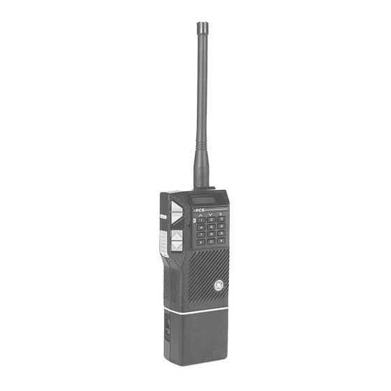
LBI-38956 • UDC interface to the outside of the radio for external 9. LCD On the 2-channel radio, the backlight can be turned on by pressing the ∧ but- options and customer programming. Backlight ton. The backlight will remain illumi- •... - Page 11 LBI-38956 Figure 1 - PCS Operating Controls...
-
Page 12: Controls And Indicators
LBI-38956 The simultaneous flashing of the BAT indicator and the Auto: Receive Channel Guard will automat- sounding of alert beeps, if programmed, indicates the radio ically be re-enabled after the PTT is acti- has failed to lock on frequency. Transmission will be termi- vated. -
Page 13: Indicators
LBI-38956 will be transmitted on the HOME channel instead NOTE of the elected channel. The short beep indicator on volume change will If the radio is scanning when the ∧ button is not be sounded when the speaker is already on. pressed and no HOME channel is programmed, the radio will stop scanning, transmit the emergency ANI code on the selected channel, and resume... -
Page 14: Alert Tones
LBI-38956 Indicates the SCAN mode is active in the 8- and Self-Test The radio performs a self-test at power- 16-channel radios. This is not used in the 2-chan- up each time the radio is turned on. A nel radios. good (passed) self-test will be indicated by three beeps, if programmed, fol- Priority 1 enabled is represented by this display (in lowed by the last radio status (channel... -
Page 15: To Place A Dtmf Call
LBI-38956 Press the MONitor button to determine if the chan- At the end of the message, if Selective mode is desired, nel is in use. Never interrupt another conversation. press and release the MONitor button to reset the Type 99 tone signalling function. -
Page 16: Digits
LBI-38956 Table 1 - PCS Function Guide FUNCTION PROGRAMMING DESCRIPTION MONITOR Button Momentary Hold Down Programmed for Channel Guard DIS/ENABLE CG MONITOR Programmed for Squelch MONITOR DIS/ENABLE CG Channel Guard Enable Manual Must re-enable CG with MON button after transmitting Auto PTT will re-enable CG Front... -
Page 17: Type 99 Tone
LBI-38956 ANI is enabled on a per-channel basis. If the Scan list includes a Type 99 channel and is SCAN enabled, the Type 99 tones will be ignored. SCAN operates In summary, ANI variables are: on a carrier and Channel Guard basis only. ID Number (0 to 8192) Channel Busy Lock-Out Start Delay (0 to 2 seconds in 100 msec incre-... -
Page 18: Pre-Scan Operation
LBI-38956 Channel Guard SCAN - This is the scanning con- Channel Activity - Channel activity is established dition where tone or digital Channel Guard must with the presence of a carrier modulated with a also be detected before locking on any channel. correct Channel Guard (if programmed). -
Page 19: Scan Operating Modes
LBI-38956 during this 2-second hang time, scan- SCAN OPERATING MODES ning will resume. Simple SCAN ∧ Pressing this button will revert the radio (selected channel) to a pre-programmed Once SCAN is activated, the radio will perform a Sim- HOME channel and stop the scanning ple SCAN routine. -
Page 20: Scanning For Channel Guard
LBI-38956 Scanning for Channel Guard TONE PROGRAMMING The scanning for Channel Guard option may be selected An IBM-compatible personal computer using MS DOS if, in addition to carrier activity alone, a correct Channel and a GE Programmer Interface Box plus the proper pro- Guard is also required to lock on a channel when scanning. -
Page 21: Ge Type 99 Format
LBI-38956 The Group Call format allows communication with all Tone D is the diagonal tone used (in GE systems only) radios in a group. The Super Group Call (in GE Tone sys- when the first and second tone frequencies are the same. tems) or Quick Call (in Motorola tone systems) allows com- The standard frequency for Tone D is 742.5 Hz, but may be munications between all radios in a system. -
Page 22: Individual Call
LBI-38956 Example 2 - Group Call 98 (also 48 and 88): Individual Call The digit "9" in Table 5 shows that Tone B is in Tone Tables 4 and 6 may also be used to determine the tone Group 4 along with 40 to 49 and 80 to 89. Tone number 8 frequencies. -
Page 23: Channel Guard
LBI-38956 Table 4 - Motorola Type Code Numbers Table 6 - Motorola Group Call Tone Groups (TG) First Digit Tone Group from Tone Group from GROUP CALL TONE GROUP which Tone A which Tone B CODE NUMBER (TONE B) Code is Selected is Selected 00-09... -
Page 24: Replacement Of Battery Pack
251, 704, 742 562, 645 REPLACEMENT OF BATTERY PACK CAUTION The battery pack used with the PCS Personal Radio must be supplied by Ericsson GE and as shown under OP- TIONS AND ACCESSORIES listed in the Table of Contents of this manual. -
Page 25: To Remove The Battery Pack From The Radio
LBI-38956 To Remove the Battery Pack from the Radio (Refer to Figure 3.) Turn the radio OFF by sliding the ON/OFF switch on the battery pack, to the OFF position. Press down on the battery pack release latch and slide the battery pack out in the direction of the re- lease latch. -
Page 26: Disposal
LBI-38956 A regular duty cycle is performed which allows the battery to expend only a limited portion of its ca- pacity. If the nickel-cadmium battery is only sparingly or sel- dom used and is left on continuous charge for one or two months at a time, it could experience reduced capacity. -
Page 27: Mechanical Parts Breakdown
MECHANICAL PARTS BREAKDOWN LBI-38956... -
Page 28: Mechanical Parts List
LBI-38956 MECHANICAL PARTS LIST PCS MECHANICAL PARTS ISSUE 1 SYMBOL PART NO. DESCRIPTION 19D902180P10 Front Cap Assembly (Conv.) 19D902180G11 Front Cap Assembly (Conv./DTMF) 19B801570P2 P901 Connector Holder. 19A705662P1 P901 Connector "MOE". 19D902631G2 Audio/Logic Board (A2). 19A702364P310 Machine screw: M3-0.5 x 10. (Quantity 4). 19A702364P304 Machine screw: M3-0.5 x 4.
Need help?
Do you have a question about the PCS 136-174 MHz and is the answer not in the manual?
Questions and answers