Table of Contents
Advertisement
Advertisement
Table of Contents

Related Manuals for Notifier SFP-400B


Summary of Contents for Notifier SFP-400B
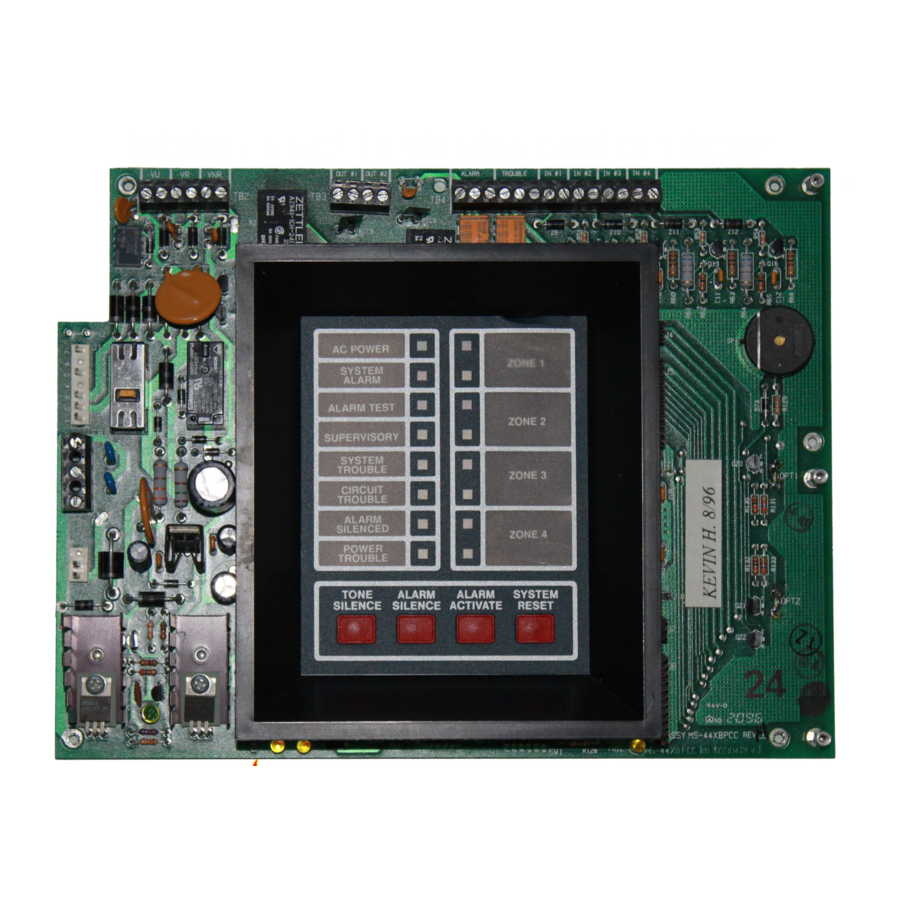
- Page 1 SFP-400B F I R E A L A R M C O N T R O L P A N E L AC POWER ZONE 1 SYSTEM ALARM ALARM TEST ZONE 2 SUPERVISORY SYSTEM TROUBLE ZONE 3 CIRCUIT TROUBLE ALARM...
-
Page 3: Table Of Contents
Table of Contents I NFPA Standards ...............4 II Additional Information .............4 1.0 The SFP-400B ..................5 1.1 Features ......................5 1.2 Circuits ......................5 1.3 Optional Boards ..................... 7 1.4 Remote Annunciator ..................8 1.5 Specifications ....................9 2.0 System Operation ................11 2.1 System Status LEDs .................. -
Page 4: I Nfpa Standards
CAN/ULC-S527-M87 Standard for Control Units for Fire Alarm Systems Other: NEC Article 300 Wiring Methods NEC Article 760 Fire Protective Signaling Systems Applicable Local and State Building Codes Requirements of the Local Authority Having Jurisdiction Notifier Device Compatibility Document,15378. ADA Americans with Disabilities Act SFP-400B 15124:G1 06/24/97... -
Page 5: The Sfp-400B
1.0 The SFP-400B Features Microprocessor-controlled. Complies with NFPA 72 Proprietary Protective Signaling System (requires Potter EFT-C Power-limited on all circuits except Municipal McCulloh Transmitter). Box Output. One Man Walk Test. Alarm and trouble resound. Disable/enable controls per Initiating Device Four Style B Initiating Device Circuits. - Page 6 Figure 1.0-1: SFP-400B Installation Diagram SFP-400B 15124:G1 06/24/97...
-
Page 7: Optional Boards
Optional Boards The SFP-400B has mounting slots for two option boards. Two of the three option modules may be installed. (see Section "Optional Modules" ) Transmitter Module (4XTM) The Transmitter Module provides a supervised output for local energy municipal box transmitter (for NFPA 72-1993 Auxiliary Protective Signaling System) and alarm and trouble reverse polarity circuits (for NFPA 72-1993 Remote Station Protective Signaling System). -
Page 8: Remote Annunciator
Retard time and Reset time must be programmed for zero seconds when connecting the alarm initiating circuit to an existing control panel. For more detailed instructions, refer to the Noti•Fire 911AC manual, P/N 74-06200-005-A. Note: 12V panels (SFP-400B) must use the 911AC. Remote Annunciator Notifier Remote Annunciator (RZA-4X) -
Page 9: Specifications
Breaker Battery (lead acid only) Maximum Charging Circuit: 27.6V, 1.5 amps Maximum Battery Capacity: 15 AH (Batteries larger than 7 AH require Notifier BB-17 or similar UL listed battery cabinet). Initiating Device Circuits Power-limited circuitry Operation: Style B (Class B) Normal Operating Voltage: 24 VDC (ripple = 1.0V peak-to-peak) - Page 10 Cabinet = 3.047" Backbox = 3.0" Door = 14.718" Backbox = 14.5" Door = 14.218" Backbox = 14" Trim Ring (TR-2-R) Figure 1.5-1: Cabinet Dimensions SFP-400B 15124:G1 06/24/97...
-
Page 11: System Operation
(not visible through door). EARTH Yellow LED that illuminates steadily on motherboard during a ground fault condition (not visible through door). MICRO FAIL Yellow LED that illuminates on motherboard when watchdog timer detects microprocessor failure (not visible through door). SFP-400B 15124:G1 06/24/97... -
Page 12: Control Switches
ALARM SILENCE), at which point the LED(s) will illuminate steadily. ALARM LED ZONE 2 TROUBLE LED Note: If zone 4 is set for supervisory, the red alarm LED is not used. ALARM LED ZONE 3 TROUBLE LED ALARM LED ZONE 4 TROUBLE LED SFP-400B 15124:G1 06/24/97... -
Page 13: Supervisory
2) With the TONE SILENCE switch held in, press (in sequence) the RESET switch, the ALARM ACTIVATE switch, and then the ALARM SILENCE switch. 3) Last Event is displayed. 4) Release the TONE SILENCE switch to return to normal operation. 5) To clear the Last Event buffer, press RESET twice. SFP-400B 15124:G1 06/24/97... -
Page 14: Installation Procedure
0.25" away from any non-power limited circuit wiring. Furthermore, all power limited circuit wiring and non-power limited circuit wiring must enter and exit the cabinet through different knockouts and/or conduits. A typical wiring diagram for the SFP-400B is shown below. Power... -
Page 15: Initiating Device Circuits
Style B Smoke Supervisory Detector Circuit (if SW1 switch 3 is set "ON") Heat Detector Manual Normally Pull Station Open Tamper Switch IN #1 IN #2 IN #3 IN #4 Figure 3.2-1: Example of Initiating Device Circuits SFP-400B 15124:G1 06/24/97... -
Page 16: 4-Wire Smoke Detector Connections
24V supply loop. is the detector current in standby. is the number of detectors on the 24V power loop which must function at the same time in alarm. is the detector current in alarm. is the end-of-line relay current. SFP-400B 15124:G1 06/24/97... -
Page 17: Output Circuits
Output Circuits Notification Appliance Circuits The SFP-400B can provide two Notification Appliance Circuits (Style Y). Each circuit is capable of providing up to 1.5 amps of current. Total current for both circuits and the unregulated power cannot exceed 2.25 amps. Refer to the Device Compatibility Chart for suitable devices. Circuits are supervised and power-limited. -
Page 18: Power
Figure 3.5-1: Diagram of Power Terminals AC Power Primary power required for the SFP-400B panel is 120 VAC, 50/60 Hz, 1.2 amps and primary power required for the SFP-400BE panel is 220/240 VAC, 50 Hz, 0.6 amps. Overcurrent protection for this circuit must comply with Article 760 of the National Electrical Code (NEC) and/or local codes. -
Page 19: Optional Modules
Cut to install module on J8. Figure 3.6-1: Option Panel Modules Notes: Optional 4XLM module for an RZA-4X Annunciator must be installed on J7 and J8 only. 4XTM and 4XZM modules can be installed in either location. SFP-400B 15124:G1 06/24/97... - Page 20 Affix the terminal identification labels provided with the option modules as shown below. (Part # 42050) Standoffs Option Board Main (4XZM shown) Board Figure 3.6-2: Installing Option Modules SFP-400B 15124:G1 06/24/97...
- Page 21 LED will indicate disconnected and/or Open Circuit conditions on the Municipal Box. Cutting the TBL jumper will allow the alarm reverse polarity circuit to open on trouble, if no alarm exists. Note: Remote Alarm, Remote Trouble and Municipal Box wiring can leave the building. SFP-400B 15124:G1 06/24/97...
- Page 22 Relay #4 limited circuit Note: Refer to the Protected Premises Unit label, located on the door of the control panel, to indicate if any dry contacts are to be used as non-power limited dry contacts. SFP-400B 15124:G1 06/24/97...
- Page 23 Connect to corresponding terminals of RZA- 4X Remote Annunciator. Remote Annunciator -- RZA-4X Single-gang Box Side View Front View Figure 3.6-3: LED Interface Module--4XLM Note: Make wiring connections with system power off. Maximum wire impedance is 50 ohm per wiring connection. SFP-400B 15124:G1 06/24/97...
-
Page 24: Dip Switch Location And Descriptions
4 will flash along with the supervisory LED. Notifi- and light Zone Trouble LED. cation Appliance Circuits 1 and 2 will activate (see Section "Output Circuits" ). Note: The Reset key must depressed after any switch configuration has been made. SFP-400B 15124:G1 06/24/97... -
Page 25: Appendix A: Power Calculations
25.0 mA c. End of Line Relays Add lines a, b, & c for subtotal Place subtotal here : Add last column for Standby Battery Current and continue to Table A-2. (113 mA for 60 hours of standby) SFP-400B 15124:G1 06/24/97... - Page 26 NFPA 72-1993 Auxiliary and Remote Station Protective Signaling Systems require 60 hours of standby. The battery charger in this panel will charge a maximum of 15 amp/hours of batteries within 48 hours (7 amp/ hour minium). Batteries larger than 12 amp/hour will require a UL listed battery cabinet (e.g. Notifier BB-17). SFP-400B...
-
Page 27: Appendix B: Nfpa Standard-Specific Requirements
Appendix B: NFPA Standard-Specific Requirements The Notifier SFP-400B has been designed for use in commercial, industrial, and institutional applications and meets the requirements for service under the National Fire Protection Association (NFPA) Standards outlined in this appendix. The minimum system components required for compliance with the appropriate NFPA standard are listed below. - Page 28 Note: Maximum loop resistance allowed for wiring from control panel to Municipal Box is 3 ohms. Municipal Box Circuit Gamewell Model M34-56 Local Energy Municipal Box Note: Municipal Box wiring can leave the building. 4XTM Transmitter Module (activated polarities shown) SFP-400B 15124:G1 06/24/97...
- Page 29 Supervision of the loop is the responsibility of the receiver. Fire•Lite RS82-9 Remote Station Receiver UL listed + - + - Remote Alarm Remote Trouble Note: Remote Alarm and Remote Trouble wiring can leave the building. 4XTM Transmitter Module (activated polarities shown) SFP-400B 15124:G1 06/24/97...
- Page 30 For additional information on the 911A, refer to document 74-06200-005. If the NOTI-FIRE 911A is not mounted in the SFP-400B backbox all connections must be in conduit, less than 20' in length in the same room.
- Page 31 NOTE on STD DACT: Place jumper over pins 2 & 3, marked DACT, when employ- ing a DACT. This directs the control panel to transmit all trouble conditions except AC LOSS. y l l y l l y l l SFP-400B 15124:G1 06/24/97...
- Page 32 Active Kissoff Trouble Primary Active AC POWER TROUBLE ALARM SUPERVISORY RESET SILENCE MODE yellow Black 120 VAC yellow 12VDC Battery Neutral 2-7AH Black Ground White Green AC Wiring for DACT/FACP must be connected to the same circuit. SFP-400B 15124:G1 06/24/97...
- Page 33 This control panel/transmitter arrangement can be employed for NFPA 72-1993 Proprietary Protective Signaling System. TROUBLE ALARM RESET SFP-400B Notes: Form-C Trouble contact which will automatically activate on any Trouble condition. Form-C Alarm contact programmed to activate on General Alarm. SFP-400B...
-
Page 34: Trouble Shooting Table
. t e l l a i t a ) s l c r i t i u c r i t i u l i a o l l r c i c r i t i u SFP-400B 15124:G1 06/24/97... - Page 35 NOTES SFP-400B 15124:G1 06/24/97...
-
Page 36: Limited Warranty
® manufacturing date-stamp control, the warranty ® is eighteen (18) months from date of original purchase by NOTIFIER 's distributor unless the installation instructions or catalog sets forth a shorter period, in which case the shorter period shall apply. This warranty is void if the product is altered, ®...
Need help?
Do you have a question about the SFP-400B and is the answer not in the manual?
Questions and answers