Table of Contents
Advertisement
Quick Links
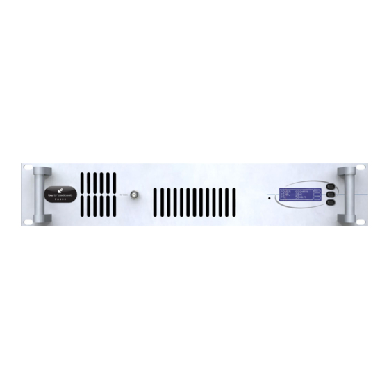
PA600 FM Broadcast Amplifier
Technical manual
No part of this manual may be re-produced in any form without prior written permission from BW Broadcast.
The information and specifications contained in this document is subject to change at any time without notice.
Copyright 2009 BW Broadcast
www.bwbroadcast.com
Advertisement
Table of Contents

Summary of Contents for BW Broadcast PA600
- Page 1 PA600 FM Broadcast Amplifier Technical manual No part of this manual may be re-produced in any form without prior written permission from BW Broadcast. The information and specifications contained in this document is subject to change at any time without notice.
-
Page 2: Table Of Contents
LCD control board parts list 3.62 Remote and alarm board parts list 3.63 Power amplifier board parts list 3.631 PSU interface 3.632 Bus bar 3.633 Controller board 3.634 15W driver board 3.635 Double pallet 3.636 Output combiner Page 2 BW Broadcast technical manual... -
Page 3: Introduction
Introduction PA600 FM POWER AMPLIFIER The BW Broadcast PA600 is a high specification FM broadcast power amplifier. Its broadband “no-tune” design allows 87.5-108 MHz operation and digital PWM techniques provide an easily adjustable and accurate automatic level controlled R.F. output of the MOS-FET power amplifier stage. -
Page 4: Safety
BW Broadcast Ltd is registered with Northern Compliance PCS number WEE/ UP3438PR/SCH and has been issued with WEE/FA0268RX as its unique producer ID by the appropriate environment agency. BW Broadcast Ltd full comply with it explicit responsibilities, subject to WEEE Collections Policy outlined in their General Terms and conditions of Sale, when it sells Electrical and Electronic Equipment (EEE) to B2B cus- tomers in the UK and EU. -
Page 5: Front And Rear Connections
Introduction FRONT AND REAR CONNECTIONS Page 5 BW Broadcast technical manual... -
Page 6: Control And Monitor Lcd
R.F. output. P.A. temperature This display indicates the temperature of the heatsink that the R.F. power transistor is bolted to. The normal operating temperature range is 40-60 degrees at full R.F. power output. Page 6 BW Broadcast technical manual... -
Page 7: Installation And Setup
The windows application has a button that can toggle the RF output of the trans- mitter. Please consult the RS232 section of this manual for more information on controlling the transmitter remotely. TRANSMITTER Page 7 BW Broadcast technical manual... -
Page 8: Fail Alarm
More info is found in the following pages of the manual. BW Broadcast can also customise the alarm / fault software to meet the requirements of major broadcasters and networks or supply N+1 solutions. More information on this and other custom features can be obtained from our technical department. -
Page 9: Rs232 Control & Monitoring
The transmitter is internally set to communicate at 9600 bps, no parity with 1 stop bit and hardware flow control. This is commonly known as 9600 8N1. If your using Windows then you can use the pre-bundled terminal program “Hyper-terminal”. This is located in the Programs -> Accessories -> Communications folder accessible Page 9 BW Broadcast technical manual... - Page 10 Unmute R.F. wait a second or two before asking for a refresh screen or by ask- ENTER Refresh screen ing for several refresh screens by pressing the 'Enter’ key a few times in succession. Page 10 BW Broadcast technical manual...
-
Page 11: Technical Data
489mm x 44mm x 322mm Weight 11 kg Voltage input 85 - 260 VAC Current input 110V - 4A / 220V - 2A Power connector IEC, FUSED and switchable Switched mode approvals UL / TUV / CE Page 11 BW Broadcast technical manual... -
Page 12: Circuit Description
R21 and CON1. R22 and C15 provide supply decoupling for the op-amp. C14,15,16,17,18 provide further decoupling and feedback for the power control feedback loop formed around side B of the op-amp. Page 12 BW Broadcast technical manual... -
Page 13: Control And Alarm Port
RF output. REG1 is a 5V voltage regulator for IC1. It is fed by 18V from the LCD control board (pin 1 on CON4). REG1 sup- ply rails are decoupled with C6, C7 and C8. Page 13 BW Broadcast technical manual... -
Page 14: Power Amplifier Board
T1 from the output of REG1 which is a switching regulator. PLL signal coming through R6 from the exciter section, can pull the T1 bias voltage low, effectively reducing the power output of T1. Page 14 BW Broadcast technical manual... - Page 15 The output of the low pass filter is sniffed by VSWR sensors R4, R5, C3, D2, C4 and R6, R7, C5, D3, C6 which generate forward and reverse RF power measurements for metering and for VSWR fault protection and alarms. Page 15 BW Broadcast technical manual...
-
Page 16: Block Diagram
Technical data BLOCK DIAGRAM Page 16 BW Broadcast technical manual... - Page 17 Technical data WIRING AND INTERNAL OVERVIEW Page 17 BW Broadcast technical manual...
-
Page 18: Lcd Control Board
Technical data 3.51 LCD CONTROL BOARD Page 18 BW Broadcast technical manual... -
Page 19: Remote Control And Alarm Board
Technical data 3.52 REMOTE CONTROL AND ALARM BOARD Page 19 BW Broadcast technical manual... -
Page 20: Psu Interface
Technical data 3.531 PSU Interface Page 20 BW Broadcast technical manual... -
Page 21: Bus Bar
Technical data 3.532 Bus Bar Page 21 BW Broadcast technical manual... - Page 22 Technical data 3.533 Controller PCB Page 22 BW Broadcast technical manual...
-
Page 23: Driver Board
Technical data 3.534 15W Driver Board Page 23 BW Broadcast technical manual... - Page 24 Technical data 3.535 Double Pallet Page 24 BW Broadcast technical manual...
-
Page 25: Output Combiner
Technical data 3.536 Output Combiner Page 25 BW Broadcast technical manual... -
Page 26: Parts List
15 Way Dual Female Dual Double Height D-Type PCB-Mount Connector CON2 R/A BNC Right Angled BNC PCB-Mount Connectors CON3 MCX PCB Mount Socket CON4 16 way Straight IDC Header 16 pin 16 Pin Dil IC socket Page 26 BW Broadcast technical manual... -
Page 27: Psu Interface
10k 20% 4mm 3314G SMT Cermet Trimmer NOTUSED SMT Cermet Trimmer Resistor NOTUSED SMT Capacitor (4X5.4mm) C2-C4,C6,C9-C16,C18-C21 100nF 100N 0805 50V Y5V Capacitor 0805 SMT Capacitor C5,C7 0805 SMT Capacitor 10uF SMT Capacitor (4X5.4mm) Page 27 BW Broadcast technical manual... - Page 28 Step down switch regulator 3.635 Double Pallet Reference Value Description R1,R6 SMT 1/8W Resistor R2,R5 100R SMT 1/8W Resistor R3,R4,R7,R8 SMT 1W Resistor R9,R17 SMT 1W Resistor R10-R12,R14-R16 SMT 1W Resistor 100R 400W Power Resistor Page 28 BW Broadcast technical manual...
-
Page 29: Output Combiner
PCB Transformer TEMP LM335Z 3.636 Output Combiner Reference Value Description 1W Resistor 120R 1W Resistor R3,R4,R5,R6,R7 120R 1W Resistor R8,R9 1W Resistor LINKS Bridge points C1,C3,C5 27pF C2,C8,C10 C4,C6 D1-D4,D6 BAT42 DIODE D5,D7 L1-L4 2.5T Page 29 BW Broadcast technical manual... - Page 30 www.bwbroadcast.com...
Need help?
Do you have a question about the PA600 and is the answer not in the manual?
Questions and answers