Table of Contents
Advertisement
Quick Links
Download this manual
See also:
Instruction Manual
Advertisement
Table of Contents

Related Manuals for Carson Reflex Wheel Ultimate touch 2.4g


Summary of Contents for Carson Reflex Wheel Ultimate touch 2.4g
- Page 1 2 , 4 G H z FH S S D i g i ta l P ro p o rti o n a l R a d i o Co n tro l S y ste m Bet ri ebsanl ei t ung Sei t e 2 - 47 I nst ruct i on M anual Page 48 - 93...
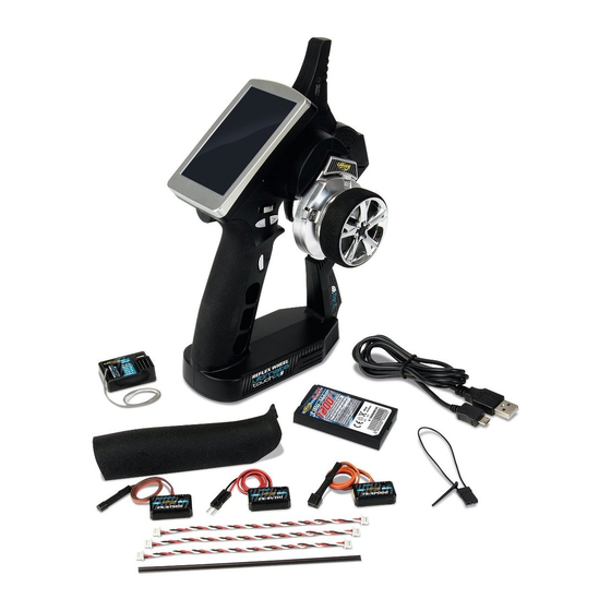
- Page 2 I n cl u d e d I te m s • 4-channel touchscreen transmitter • Micro telemetry receiver • Telemetry sensor for speed, temperature and battery voltage • LiPo TX battery 1200 mAh N° 500500516 • USB charger lead •...
- Page 3 Ch a rg i n g th e TX b a tte ry 1. Insert the TX battery in the compartment on the 3. The mini USB connecter must now be connected underside of the remote control and close the to the USB port, which is located on the back of compartment again with the closure cover.
- Page 4 Fe a tu re s o f th e 2 , 4 G H z R e m o te Co n tro l The transmitter technology at 2,4 GHz is fundamen- Nonetheless, within each second countless signals tally different in some aspects from the technology are received and evaluated by the receiver.
-
Page 5: Operating Procedure
O p e ra ti n g P ro ce d u re Many publications say that the setup sequence • After operation: Disconnect the battery from the for the transmitter and receiver don’t play a role control unit. Turn the receiver off, and then the anymore with 2,4 GHz sets. - Page 6 Eq u i p m e n t fo r Co m b u sti o n En g i n e Receiver batteries and two servos are not included in the kit. Servo Channel 3 To receiver battery Receiver switch (not included) Receiver Servo Channel 3...
- Page 7 R e ce i ve r co n n e cti o n s exp l a i n e d CH1-CH4: Connection to the relevant channel (servo/ESC, etc.) BIND, VCC: Connection for binding connector and power supply. OUT: ASbus connection for outgoing PPMS data signals and for connecting the serial bus module to extend the channels further.
- Page 8 S e n so rs/ m o d u l e s co n n e cti o n s exp l a i n e d Tel em et ry m odul e FS- SPD 02 Speed recognition module 1 cm Procedure: 1.
- Page 9 Tel em et ry m odul e FS- SVT01 Battery voltage recognition module Procedure: 1. Connect one end of the 3-pin connecting cable 3. Next, connect the red and black contact connector to the “Out” terminal of the telemetry module to the balancer terminal of your LiPo driving and the other end to the “IN”...
- Page 10 Exte rn a l V i e w o f Tra n sm i tte r 2,4 GHz Aerial Stylus for touchscreen Status LED Trim switch TR2 Trim switch TR1 Control steering wheel Trim switch TR4 Trim switch TR3 Trim switch TR5 Switch SW3 Switch SW1 Power switch...
- Page 11 P o w e ri n g o n th e R C sy ste m 1. Connect all the components as described in the operating instructions. 2. Switch on the transmitter at the power button. Power switch On/Off 3. Connect the RX battery to the receiver or the driving battery to the ESC.
-
Page 12: Main Screen
M e n u n avi g a ti o n M ai n screen Transmitter battery Model name Receiver battery Receiver signal Break mixing Receiver sensor´s state feedback Throttle curve Mixes Race timer Engine cut Turn sound Throttle idle Steering channel state Throttle channel state Boat mode... - Page 13 M ai n m enu Settings Main menu: Main menu: Back Page 1 Page 2 The main menu can be accessed by touching the • To display the next page, touch the current page settings icon at the bottom of the main screen. anywhere on its right part and slide it to the left.
- Page 14 Funct i ons i nt erf ace All functions use a set of standard user interface These 2 buttons respectively enable and disable objects. The bottom tray can contain the following the current function. buttons: The default button sets back the current page parameters to their default values.
- Page 15 A vertical menu allows to select one option among several. This example selects the ABS parameter to set. The right gray vertical bar indicates the lengths of the menu and the current position in it. • To scroll down a vertical menu, touch it anywhere on its bottom and slide it up.
- Page 16 Most of functions are set using a dialog bog. This example contains the following objects: A dialog box contains a set of different objects. • The value of the selected parameter is displayed Touching a button will execute or select the in the value box on the top of the dialog box.
- Page 17 End poi nt s The end points function individually adjusts the low In this example, the throttle trigger was moved to and high travel limit of each servo on the 4 channels. it acceleration side thus selecting the high side end Set the end points according to your model mechanics.
-
Page 18: St Eeri Ng Exponent I Al
St eeri ng exponent i al The horizontal dotted line shows a steering wheel The steering exponential function modifies the 20% under the neutral position but the horizontal transfer curve between the steering wheel and the dotted Iine indicates that the resulting servo throw channel 1. -
Page 19: Throt T L E Neut R Al
St eeri ng m i x There are 4 different types of steering control. In this example, the reverse phase type is selected and the steering wheel is half turned to the left. Front side: the channel 1 controls the front steering. -
Page 20: Throt T L E Exponent I Al
Throt t l e exponent i al The throttle exponential is identical to the steering exponential but applies to the channel 2. The activation of the throttle exponential function can be assigned to a push button. The throttle rate can be assigned to a trim switch. The throttle exponential can be assigned to a trim switch. - Page 21 A. B. S. The automatic brake system (A.B.S.) pulses the • Duty cycle: set the proportion of the time the brakes to avoid blocking the wheels and losing brakes are applied and the time the brakes control of the vehicle. are released.
-
Page 22: Throt T L E Speed
Throt t l e speed The throttle speed is identical to the steering speed but applies to the channel 2. The throttle go speed can be assigned to a trim switch. The throttle return speed can be assigned to a trim switch. -
Page 23: Engi Ne Cut
Engi ne cut When activated, the engine cut ignores the throttle trigger position and set the throttle to a predefined position. It can be used to turn off the ignition of a gas powered vehicle. In this example, the throttle trigger is at full throttle but since the engine cut function is activated and set to -90%, the throttle servo brakes slightly. - Page 24 The activation of the channel 3 exponential function can be assigned to a push button. The activation of the channel 3 ABS function can be assigned to a push button. The activation of the channel 4 exponential function can be assigned to a push button. The activation of the channel 4 ABS function can be assigned to a push button.
-
Page 25: D I Spl Ay Servos
D i spl ay servos This function displays in real time the position of the 4 servos. The test button let the 4 servos to move slowly between their respective end points. This allows to test the consistency of the mechanics of the model. - Page 26 • Lap timer: the lap timer is an up timer. Once started, the start button becomes the lap button. Each time the lap button is touched, the time elapsed since the last lap or the timer start is displayed for 3 seconds and recorded in the lap memory.
-
Page 27: Keys Function
Keys f unct i on A function can be independently assigned to each trim switch and push button. To assign a function to a trim switch or push button, touch its corresponding button in the Keys function dialog box. A menu displays all the available functions for the selected trim switch or push button. - Page 28 Name: modifies the name of the current model. Select model: select the model configuration to load and use. In this exa- mple, the first model is selected. Simply touch ano- ther model menu item to load and use it. Copy model: copies a model configuration to another. The second menu selects the target model The target configuration is lost and replaced by the configuration to copy to.
- Page 29 Reset model: reset all the current model configu- ration settings to their default. A confirmation is requested. In this example, the first modells selected and will be reset to its default configuration after having touched the Yes button. RX set up Set up the receiver.
- Page 30 • Fallsafe: In case of a loss of signal, the receiver Touch a channel to set its failsafe behavior. If acti- can be configured to set one or several servos to vated, set the channel to the desired position using a predefined position.
- Page 31 Choose sensors: the main screen can display the Press the interface setup button corresponding to value of up to 4 sensors. This function selects which the desired servo or touch Cancel to return. sensors to display. Select the main screen slot to attribute (1 to 5).
- Page 32 Speed and distance: As shown in picture, if a Set rotation length: Set the vehicle travel distance rotation speed sensor is connected to the receiver, corresponding to one rotation speed sensor. This this function set up the virtual speed and odometers distance is used to control the virtual speed and sensors.
- Page 33 Syst em The system menu sets various system wide Sound: Turn on or turn off the sound of the parameters. transmitter. Auto power off: After five minutes of no operation, the transmitter will sound an alarm and flash its LED. After five more minutes of no operation, the transmitter will automatically shut down.
- Page 34 Backlight: adjust the level of the backlight. A high Language: the user interface can be displayed in brightness, can be useful in a very bright environment several languages. like a sunny weather. The brighter the backlight is the shorter the battery of the transmitter lasts. Firmware update: the internal software (firmware) of the transmitter can be updated using the USB interface connected to a PC computer.
- Page 35 USB function Description: • None: the USB interface can be used only to charge the battery of the transmitter. • FS-iT4 emulator: when connected to a computer, the transmitter acts as a standard HID with 4 axes (one for each channel) and 3 switches (SW1, SW2 and SW3) and can be used as the main controller in any compatible simulation software.
- Page 36 Al arm f unct i on descri pt i on Audible alarm 1. When the transmitter battery is low and the voltage 4. When the timer goes off, the system will make a is lower than 3.75V, the system will make alarm sound “Bi, Bi, Bi, Bi’”...
Need help?
Do you have a question about the Reflex Wheel Ultimate touch 2.4g and is the answer not in the manual?
Questions and answers
Здравствуйте, подходят ли приёмники fly sky?
No, Fly Sky receivers do not work with the Carson Wheel Ultimate Touch 2.4g. The receiver only accepts signals with the coding from its own transmitter.
This answer is automatically generated