Sign In
Upload
Download
Table of Contents
Contents
Add to my manuals
Delete from my manuals
Share
URL of this page:
HTML Link:
Bookmark this page
Add
Manual will be automatically added to "My Manuals"
Print this page
×
Bookmark added
×
Added to my manuals
Manuals
Brands
Galleon Manuals
UPS
1K
User manual
Galleon 1K User Manual
Rackmount online ups
Hide thumbs
1
Table Of Contents
2
3
4
5
6
7
8
9
10
11
12
13
14
15
16
17
18
19
20
21
22
page
of
22
Go
/
22
Contents
Table of Contents
Troubleshooting
Bookmarks
Table of Contents
Table of Contents
1 Important Safety Warning
Transportation
Preparation
Installation
Operation
Maintenance, Service and Faults
2 Installation and Setup
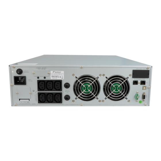
Rear Panel View
Install the UPS
Setup the UPS
Communication Port
Battery Replacement
Battery Kit Assembly (Option)
3 Operations
Button Operation
LCD Panel
Audible Alarm
LCD Display Wordings Index
UPS Setting
Operating Mode Description
Faults Reference Code
Warning Indicator
4 Troubleshooting
5 Storage and Maintenance
6 Specifications
Advertisement
Quick Links
1
Operation
2
Maintenance, Service and Faults
3
Battery Replacement
4
Lcd Panel
5
Audible Alarm
6
Faults Reference Code
7
Troubleshooting
Download this manual
User Manual
Rackmount Online UPS
1K/1.5K/2K/3K
Uninterruptible Power Supply System
Version: 1.1
Table of
Contents
Previous
Page
Next
Page
1
2
3
4
5
Advertisement
Table of Contents
Need help?
Do you have a question about the 1K and is the answer not in the manual?
Ask a question
Questions and answers
Related Manuals for Galleon 1K
UPS Galleon 6KRT User Manual
6k/10k rack/tower online ups (31 pages)
UPS Galleon 2K User Manual
Rackmount online ups (22 pages)
UPS Galleon 3K User Manual
Rackmount online ups (22 pages)
This manual is also suitable for:
2k
3k
1.5k
Table of Contents
Print
Rename the bookmark
Delete bookmark?
Delete from my manuals?
Login
Sign In
OR
Sign in with Facebook
Sign in with Google
Upload manual
Upload from disk
Upload from URL


Need help?
Do you have a question about the 1K and is the answer not in the manual?
Questions and answers