
Subscribe to Our Youtube Channel
Summary of Contents for Teleste CXE180
- Page 1 User Manual CXE180 59300401 Rev.001 26.5.2010 1(12) CXE Series User Manual Teleste Corporation CXE180 Universal amplifier...
-
Page 2: Table Of Contents
User Manual CXE180 59300401 Rev.001 26.5.2010 2(12) Contents Introduction ......................3 Technical specifications ................... 4 Block diagram ....................5 Installation ......................6 Housing ........................ 6 Interfaces ......................6 Powering ......................7 Front panel ......................8 Jumper settings ....................9 Adjustments ..................... 10 Downstream signal path .................. -
Page 3: Introduction
3(12) Introduction CXE180 is a compact dual output amplifier. It has two gain modes in one product. Gain can be selected on the field according to wanted operation. Higher gain (40 dB) is designed for distribution purposes and lower gain (32 dB) is suitable for line extender use. -
Page 4: Technical Specifications
User Manual CXE180 59300401 Rev.001 26.5.2010 4(12) Technical specifications Downstream signal path ( all values with the diplex filters) Frequency range 47 / 54 / 70 / 85 / 108..1006 MHz Return loss 18 dB Gain 40.0 dB Input attenuator control range 0...15 dB @ 1 dB... -
Page 5: Block Diagram
User Manual CXE180 59300401 Rev.001 26.5.2010 5(12) Block diagram Flat High gain Sloped Cable simulation Low gain Flat 0 dB -10 dB TP -20dB TP -20dB OUT 2 OUT 1... -
Page 6: Installation
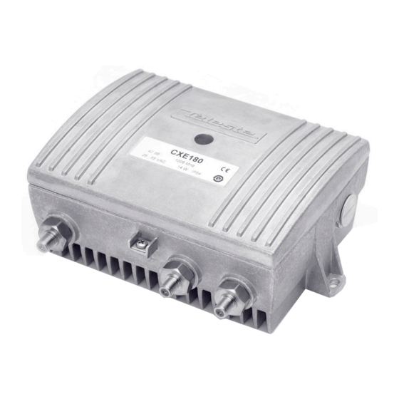
Figure 1. CXE180 amplifier 1) Input, 2) Ground, 3) Output port 2, 4) Output port 1 Interfaces Underneath the CXE180 amplifier there are three cable connection points: input and two outputs. The amount and function of actual connectors varies with the chosen configuration. -
Page 7: Powering
FUSE Figure 3. Remote cable connector The locally powered CXE180 amplifier is connected to the main voltage of 180…255 V AC via its own power cord. The power supply is double shielded and does not require separate grounding. However, the amplifier housing has to... -
Page 8: Front Panel
User Manual CXE180 59300401 Rev.001 26.5.2010 8(12) Front panel 8910051 Figure 4. CXE180 Front panel RF input 10) Output test point, -20dB Input test point, -20 dB directional coupler transformer 11) Output module (see table 1) Input diplex filter 12) RF output 1... -
Page 9: Jumper Settings
User Manual CXE180 59300401 Rev.001 26.5.2010 9(12) Jumper settings Cable simulator Mid stage gain Mid stage slope jumper selection jumper selection jumper (Figure 4 pos. 6) (Figure 4 pos. 7) (Figure 4 pos. 8) high gain flat flat (40 dB) -
Page 10: Adjustments
User Manual CXE180 59300401 Rev.001 26.5.2010 10(12) Adjustments Downstream signal path The output stage uses a GaAs hybrid to improve RF performance over the entire 47 to 1006 MHz passband. The distribution path, through the use of plug- in output modules (Figure 4 pos.11), can be set up for a variety of output configurations. -
Page 11: Upstream Signal Path
User Manual CXE180 59300401 Rev.001 26.5.2010 11(12) Upstream signal path Optional return path operation needs plug-in diplex filters (Figure 4 pos. 3 and 9).The available diplex filter types are CXF030 (30/47 MHz), CXF042 (42/54 MHz), CXF050 (50/70 MHz), CXF065 (65/85 MHz) and CXF085 (85/108 MHz). -
Page 12: Legal Declarations
This document is protected by copyright laws. Unauthorized distribution or reproduction of this document is strictly prohibited. Teleste reserves the right to make changes to any of the products described in this document without notice and all specifications are subject to change without notice.
Need help?
Do you have a question about the CXE180 and is the answer not in the manual?
Questions and answers