
Summary of Contents for Eicher EE483TC
- Page 1 OPERATION AND MAINTENANCE MANUAL EE483TC & EE483TCI Power Generation Engine Pub. No : M190456 : 01 Nov 2012...
-
Page 2: Table Of Contents
CONTENTS Section Details Page No Introduction-Operation & Maintenance Part I Manual Part II Eicher Engine - General Information Engine Familiarization 3 General Information 3.1- Engine Identification 3.2- Engine Nomenclature 3.3- Engine orientation and Parts 6 to 8 Illustration Part III 3.4- Technical Specification- Engine... - Page 3 PART I-INTRODUCTION - OPERATION & MAINTENANCE MANUAL We are glad to introduce us as VE Commercial Vehicles Ltd (VECV), manufactures of EICHER EE483TC and EE483TCI Power Generation Engine owned by you. VECV is committed to being the leader in customer satisfaction in India and emerging markets.
-
Page 4: Part Ii: Eicher Engine General Information
PART II: EICHER ENGINE GENERAL INFORMATION: Eicher EE483TC Engines manufactured by VE Commercial Vehicles Ltd (VECV) are direct injection, four Strokes, Water cooled, and Turbo charged Diesel Engines designed to suit Power Generation application. Eicher EE483TCI Engines manufactured by VE Commercial Vehicles Ltd (VECV) are direct injection, four Strokes, Water cooled, Turbo charged, Intercooled Diesel Engines designed to suit Power Generation application. -
Page 5: Engine Familiarization
Engine name plate contains the information as shown in the figure 1, 2 and 3. Engine Sl No is also punched on the Cylinder block as shown in the figure 4. Fig- Fig 2 – EE483TC-48 Kw 1- EE483TC-38 Kw Engine Sl No Punched on Cylinder Block... -
Page 6: Engine Nomenclature
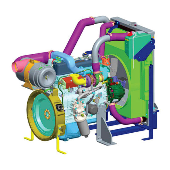
Year of production (A to W), A= 2010 W=2028. Note: “I” is omitted Type of fuel used (D=Diesel) Version: N=NA (Naturally aspirated) C= TCI (Turbo Charged intercooled) T=TC (Turbo Charged) Swept Volume per cylinder 83=0.83 Litres No. of Cylinders (4 or 6) EICHER... - Page 7 3.3 ENGINE ORIENTATION AND PARTS ILLUSTRATION (EE483TC -TURBO CHARGED ENGINE): Radiator Strip-Support radiator Radiator Cap Shroud Radiator Hose- Radiator In Guard Fan Radiator Tank Condenser Fan Cooling Radiator Bracket – Radiator Support Pipe- Fuel filter to Fuel injection pump Cushion-Radiator Support Bracket...
-
Page 8: Engine Orientation And Parts
ENGINE ORIENTATION AND PARTS ILLUSTRATION (EE483TC -TURBO CHARGED ENGINE) CONTD: Hose – Air cleaner Pedestal- Rear for Transportation Switch-Choke Air Cleaner Hose- turbo charger in Pipe- Lubrication Turbocharger Turbo charger Manifold- Exhaust Filter Oil – Main Cooler- Oil Bend Exhaust... -
Page 9: Radiator
ENGINE ORIENTATION AND PARTS ILLUSTRATION (EE483TCI -TURBO CHARGED INTERCOOLED ENGINE): Hose-Air Filter to Pipe TC in B Intercooler Assy Pipe TC in B Hose – Thermostat to Radiator Hose- Intercooler Outlet Pipe-Turbo Charger to Intercooler inlet Pipe TC in A Hose-Pipe Intercooler inlet to Intercooler in... - Page 10 Gear Type Oil Filter-Main Type / Nos. Paper Type / Single Oil Filter-By Pass Type Spin on Type Paper Oil Cooler Type Shell Type API CH4-SAE 15W40 / EICHER Premium Diesel Specification / Engine Oil Engine Lubricating Oil Grade / Recommendation...
- Page 11 Type / Nos. Cartridge type / 2 Nos. Cooling Method Method Liquid Cooling / Forced Circulation Centrifugal Water Pump Type Specification / JIS-K-2234-94 / EICHER GENUINE RADIATOR Coolant Recommendation COOLANT Engine Cooling Fan Type Pusher Electrical System Starter Motor Make / V / Kw Bosch / 12 / 1.9 Kw...
-
Page 12: Engine Systems And Function
Electrical system is required for engine starting, battery charging and sensing of critical engine operating parameters. The construction of Eicher diesel engine is divided in to five parts as below. Air intake and Exhaust System... - Page 13 further increased. Due to more air with desired density of air inducted into the engine there will be complete combustion resulting in: • Increase in power and torque without increasing the size of the engine. • Improves fuel economy. • Reduce engine noise.
- Page 14 SILENCER: Silencer is used to reduce the noise of exhaust gas / Smoke. The exhaust gas is sent through a number of small holes provided inside the silencer which results in sudden expansion of exhaust gases. This results in reduction in exhaust noise. For specific applications like Power Generation residential mufflers are used to achieve reduction in noise levels.
-
Page 15: 2- Lubrication System
3.5.2 LUBRICATION SYSTEM: The engine has a forced lubrication system. The main functions of the Lubrication systems are as follows: Lubricates moving engine parts by forming a thin film of oil between components and prevents • metal to metal contact This oil film is capable of absorbing shocks in Con-rod Bearings and Gear train •... - Page 16 SCHEMATIC DIAGRAM OF LUBE OIL FLOW: 1. Oil Strainer 4B. Bypass valve 8C. Timing gear 15. Auxiliary gallery 2. Oil Pump 16. Oil jet for piston cooling 5. Main oil gallery 9. Connecting rod bearing 2A. Relief valve 6. Engine oil pressure switch 17 Piston 10.
- Page 17 OIL COOLER: Shell type oil cooler facilitates heat dissipation from engine lubricating oil and maintains engine lubricating oil temperature and viscosity to the desired levels. The Pressurised oil from oil pump is sent into the oil cooler for cooling the hot engine oil. The coolant from the cylinder block is passed through oil cooler element, which takes away the heat from the engine oil.
-
Page 18: 3- Fuel System
FUEL INJECTION PUMP LUBRICATION: Oil from oil gallery flows through benzo tube to FIP & lubricates camshaft and governor mechanism and then drained to the oil sump from the FIP gear side of FIP housing. Pipe Lubrication - FIP 3.5.3 FUEL SYSTEM: The function of fuel system is to feed the engine with clean and sufficient quantity of fuel as per designed requirements. - Page 19 WATER SEPARATION FROM FUEL: The air moisture trapped inside the fuel tank gets condensed during night time, becomes water and mixes with diesel. If this water is allowed to flow through the fuel system it can damage the FIP and nozzle. Since the engines are used for power generation application which is operated under stationery condition, the fuel tank acts as water separator.
- Page 20 Fuel from feed pump flows into the outer side of the filter housing and filtered by the element and supplied to the fuel injection pump. The above diagram shows the flow path of fuel in fuel filter. FUEL INJECTION PUMP: The Bosch in line type fuel injection pump is used.
-
Page 21: 4- Cooling System
3.5.4 COOLING SYSTEM: The function of the cooling system is to absorb and dissipate heat generated during combustion thereby maintaining engine coolant temperature as per designed parameters. To ensure the same the engine is cooled by forced circulation of coolant by the water pump. Radiator cooling fan driven by the V Belt from the water pump pulley charges cold air through the radiator fins which carries away the heat from the coolant. - Page 22 THERMOSTAT: The thermostat is of a bottom bypass configuration, has a valve controlled by a special wax enclosed in a pellet. The wax changes from solid to liquid as it is heated, involving volumetric change for regulating the flow of coolant. The changes in the valve position with varying coolant temperatures regulate the flow rate of coolant into the radiator and water pump (bypass side), thus controlling...
-
Page 23: Part Iv Engine Electrical System
PART IV- ENGINE ELECTRICAL SYSTEM: 12 V, Negative Earthing Electrical systems is used on the engine. Electrical systems consist of the following and its usage is discussed as below. Name of Operating Usage Illustration Component Voltage Starter Motor Engine Starting Battery Battery Charging / W Point Signal Charging... - Page 24 1.Signal to Engine Control Unit / Stop Relay for Stopping the Pressure Switch engine in the event of Low Lubricating Oil Pressure 2. NC-Normally Closed 1.Signal to Engine Control Unit / Stop Relay for Stopping the Engine in the event of Air Cleaner Choke Switch Element Clogging leading to High Intake air restriction...
-
Page 25: Part V Safety Guidelines
PART V-SAFETY GUIDELINES This section laid guidelines for safety of personal and equipment. Safety should be the utmost priority during installation, operation and maintenance of the engine and equipment. General safety instruction, accident prevention regulations and safety precaution defined by law must be observed. - Page 26 HOT SURFACES While running engine and exhaust system surface are at elevated temperature contact with them can cause severe burn injury. Always wear personnel protective equipment (PPE’s) when working on hot surfaces. Start working on engine when it cools down. HANDLING ENGINE FLUIDS Most Chemicals used in engines such as old engine oil, corrosion inhibiters;...
-
Page 27: Part Vi Recommended Routine Checks By User
PART VI: RECOMMENDED ROUTINE CHECKS BY USER While all due care has been taken to ensure trouble free performance of the engine, a few simple routine checks by the actual user will help to identify and fix the issue at right time which will avoid major breakdown and down time of the equipment. - Page 28 COOLANT CHECKING AND TOPPING UP: Keep observing the reservoir tank coolant level and top up with genuine recommended coolant to the maximum Level mark. RUBBER HOSES: Perform visual checks of all rubber hoses for cracks / damage. Report to the authorized service centre and correct if necessary.
- Page 29 ENGINE STARTING CARE: During Starting of the engine, long cranking and holding the ignition key in on condition keeping starter motor engaged with flywheel ring gear for longer period will affect the life of starter motor. The precautions are as below. ...
-
Page 30: Part Vii Engine Inspection And Maintenance
PART VII: ENGINE INSPECTION & MAINTENANCE Needless to say, any equipment needs scheduled and preventive maintenance care. Engine being a prime mover also needs attention at right time in order to ensure trouble free performance of the equipment. By strictly adhering to the following Scheduled & preventive maintenance, use of genuine spares, Lubricants and coolant will deliver satisfactory performance of the engine and avoid down time of the equipment. - Page 31 Install and retighten the Drain Plug. Ensure to replace the Copper Gasket of the drain plug with new. Fill with recommended quantity of EICHER GENUINE lubricating oil through the Filler Cap. Drain Plug Allow 10 Minutes to facilitate oil to reach the oil Sump.
- Page 32 ENGINE LUBRICATING OIL RECOMMENDATION: DETAILS ENGINE EICHER EE683TCI SPECIFICATION API CH4 /CI4 SAE15W40 EICHER GENUINE OIL & LUBRICANTS EICHER PREMIUM DIESEL ENGINE OIL QUANTITY REQUIRED FOR REPLACEMENT 11 LITERS (Including Filters) DURING SCHEDULED MAINTENANCE ENGINE MAIN OIL FILTER REPLACEMENT: Unscrew the drain plug and remove oil from main oil filter casing.
- Page 33 ENGINE BY PASS FILTER REPLACEMENT: Remove used spin on type by pass filter by using bypass filter wrench (Part No153801). Damage and Discard the same. Apply oil film on the bypass filter gasket before fitment Fit the new bypass filter by fully tightening with the hand and then using bypass filter wrench.
- Page 34 ENGINE FUEL FEED PUMP GAUZE FILTER CLEANING: Since the fuel from fuel tank is passed first through feed pump, due to suction process foreign particles / dust from Fuel if allowed through the fuel system affects the reliability of Fuel injection pump components. Hence a gauze filter (Baby Filter) is provided at the inlet side of fuel pump which filters any foreign particles/dust that is being is passed through it.
- Page 35 CAUTION! : Do not strike the element or strike it against a hard object to remove dust. Primary Element Should be removed for cleaning only when Choke switch provides alarm. Clean only the primary filter element. The safety Element should never be cleaned but only replaced at the recommended intervals.
- Page 36 14.8 Refer to “Engine Technical Specification” for Qty of Coolant Required for the respective Engine CAUTION! : Be sure to use EICHER Genuine Coolant Never Mix it with any other coolant, anti-freezes or anti rusts. Ensure that the caps of the radiator assembly and that of coolant are tightened.
- Page 37 INSPECTION AND ADJUSTMENT OF VALVE CLEARENCE: Valve clearance adjustment should be performed when the engine is cold. The engine was warm while performing the maintenance activities as the engine was started before starting the maintenance activities. The engine will become cooler by the time lubricating oil and filter replacements were completed. Inspect and adjust the valve clearance when the engine is cold by using the following procedure.
- Page 38 Install specified thickness gauge between the rocker and valve cap to check for clearance. If the valve clearance is out of nominal value, loosen the lock nut and turn the adjusting screw to the extent that the thickness gauge moves slightly tight. After adjustment hold the adjusting screw in position with a screw driver and tighten to secure the lock nut.
- Page 39 After bleeding the air check for performance of engine on load, Oil leaks, Coolant leaks, Engine noise level and for any other abnormalities before handing over to the end user.
- Page 40 PART VIII: ENGINE TROUBLE SHOOTING GUIDLINES: Sl no Symptom Probable Cause Remedy Inadequate fuel quantity Add Fuel Poor Quality of fuel or oil Change fuel or Oil used Bleed the system. If trouble persists Check for Loose Piping & Connectors Air trapped in fuel system ...
- Page 41 Sl no Symptom Probable Cause Remedy Incorrect fuel or oil used Change fuel or oil Idling speed setting not ok Adjust idling stopper bolt Bleed the system. If trouble persists Check for Loose Piping & Connectors Air trapped in fuel system ...
- Page 42 Sl no Symptom Probable Cause Remedy Incorrect Valve Clearance Reset Injection Nozzles not clean Clean Injection pressure not ok Rectify Injection Spray Pattern Poor Repair / Replace Nozzle Low engine Compression (Worn out piston and Repair / Replace worn out parts sleeve/valve seat leakage/ cylinder head gasket leakage) Air cleaner Clogged...
- Page 43 Sl no Symptom Probable Cause Remedy Check / Correct or Replace. Defective Cylinder head gasket Worn Valve and Valve Seat Poor Compression Pressure Valve Spring set Worn or damaged piston ring Excessive clearance between piston and cylinder sleeve Restricted air duct from turbo compressor to intake Rectify...
-
Page 44: Radiator Cap
Sl no Symptom Probable Cause Remedy Full Load stopper on Adjust and tighten the stopper bolt governor control lever loose Excessive Valve clearance Adjust Incorrect fuel injection timing Reset Clean nozzles and adjust injection Injection Nozzle defective pressure if required. Check spray pattern and change Nozzle if required Improper Exhaust Air cleaner or muffler not in... -
Page 45: Rocker Cover
Sl no Symptom Probable Cause Remedy Engine Overheating Engine overloaded Avoid Overload Piping’s and hoses not Rectify securely installed Injection Pump, water Pump and other auxiliaries not in Check and adjust good condition or improperly Engine Noise- Comes installed from outside the Adjust belt tension and replace if V Belt Loose or damaged engine... - Page 46 Sl no Symptom Probable Cause Remedy Injection Pump Coupling Align timing marks and retighten bolts loose Noise from around the Injection pump piping Rectify / Replace injection pump cracked or loose connection Injection timing incorrect Reset Clamping bolts & nuts of intake &...
- Page 47 Sl no Symptom Probable Cause Remedy Improper Engine oil Viscosity Use correct grade of oil Check for oil Leaks – Oil filter/Oil cooler/Oil Repair leaks Pan/Piping’s/Rocker cover Lines in cooling system Repair leaks of oil cooler, water jacket leaking Bearings worn Replace Front or Rear Crankshaft oil Repair defective parts or replace...
- Page 48 Sl no Symptom Probable Cause Remedy Injection Nozzles defective. Check for Clean Nozzle/Adjust injection pressure Injection Pressure/Spray if incorrect/Replace nozzles tip or Condition/Seat tightness Nozzle if required Excessive fuel consumption Engine Overloaded Avoid overloading Repair/Calibrate FIP from Bosch Defect in FIP authorized service centre...
- Page 49 Regd. Office & Works : 102, Industrial Area No.1, Pithampur - 454 775. Distt. Dhar (M.P.) India. Tel.: 91 - 7292 - 402633. Fax : 07292 - 402611 Website : eicher.in\eth...
Need help?
Do you have a question about the EE483TC and is the answer not in the manual?
Questions and answers