Table of Contents
Advertisement
Quick Links
Advertisement
Table of Contents

Subscribe to Our Youtube Channel
Summary of Contents for FHF ExResistTel IP2
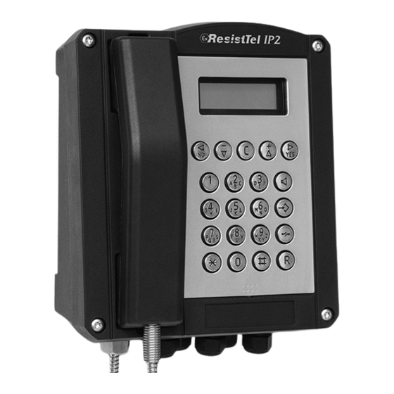
- Page 1 VoIP-telephone Operating instructions FHF B 9711 03/13...
- Page 2 Texts and illustrations have been compiled and software created with the utmost care, however errors cannot be completely ruled out. This documentation is therefore supplied under exclusion of any liability or warranty of suitability for specific purposes. FHF reserves the right to improve or modify this documentation without prior notice. Note Please read the operating manual carefully before installing the telephone.
-
Page 3: Table Of Contents
Relay Connection ..............16 Setup ................17 Operating Position ............17 Information..............18 Service................18 Care and Maintenance ........... 18 Disposal................18 Warning and Security Instructions........ 18 Requirements..............21 Type Label ..............21 Declarations and Approvals ........... 22 Manual ExResistTel IP2 Page 3... - Page 4 EC Type Examination Certificate ExResistTel IP2 ..22 IECEx Certificate of Conformity ExResistTel IP2 ..25 Declaration of Conformity ExResistTel IP2 ....26 Technical Data..............28 Page 4 Manual ExResistTel IP2...
-
Page 5: General
1.2 Description The telephone type ExResistTel IP2 is realized according to the following type of protection: • Type of ignition protection: Ex e [ib] mb IIC T4 Gb •... -
Page 6: Construction
1.3 Construction 1.3.1 Housing The telephone type ExResistTel IP2 has a non coloured housing made of an electrostatic conductive pressed basic material and a stainless steel keypad. Optionally the housing can be coloured with an electrostatic conductive colour. -
Page 7: Electrical Characteristic Parameter
To observe the EMC rules with netting shielded cables have to be used. Note Using a power supply via PoE it is only allowed to use the unused data cable pairs of a 10/100 Mbit/s Ethernet cable for the power. Manual ExResistTel IP2 Page 7... -
Page 8: Lan Interface 10/100 Base-Tx According To Ieee 802.3 (Not Intrinsically Safe)
• U = DC 230 V = 0.5 A = 100 W For this connection cables with a transversal section of 0.75 mm² to 4 mm² are allowed to be used only. Page 8 Manual ExResistTel IP2... -
Page 9: Cable Shield
• The bare end of the drilled cable shield may be connected directly (The terminals are approved for connecting flexible wires) or otherwise connected with a mounted end sleeve for strands. • Advantageously these cable works should be done before inserting the cable into the housing. Manual ExResistTel IP2 Page 9... -
Page 10: Configuration Plug Connector
For this connection cables with a transversal section of 4 mm² to 6 mm² can be used. 1.4.9 Voltaic Isolation The supply DC, the supply PoE, the LAN interface and the intrinsically safe headset are safety voltaic separated up a voltage of 250 V Page 10 Manual ExResistTel IP2... -
Page 11: Voltaic Isolation Of The Relay Contacts
1.4.10 Voltaic Isolation of the Relay Contacts The two potential free relay contacts are safety voltaic separated against each other up to a voltage of 440 V Manual ExResistTel IP2 Page 11... -
Page 12: Commissioning
For operation and commissioning, the application of standard IEEE 802.3 is compulsory. The ExResistTel IP2 telephone must be connected to a LAN (Local Area Network) connection. The telephone can be powered with PoE (Power over Ethernet). In this case the power supply must use the free cable pairs. Using the phantom power supply is not possible and not allowed. -
Page 13: Cable Screw Caps
Ø 5.5 mm to Ø 13 mm locking torque coupling ring 2.5 Nm to 3.5 Nm cable 2.1.2 Inside View of Telephone upper Part Figure 1: Inside View of upper Part Telephone ExResistTel IP2 Manual ExResistTel IP2 Page 13... -
Page 14: Inside View Of Telephone Lower Part
2.1.3 Inside View of Telephone lower Part Figure 2: Inside View of lower Part Telephone ExResistTel IP2 2.1.4 Drilling Diagram Figure 3: Drilling Diagram Wall Mounting Page 14 Manual ExResistTel IP2... -
Page 15: Connecting Plan
2.1.5 Connecting Plan Figure 4: Terminals of the Explosion Proof VoIP Telephone ExResistTel IP2 2.1.6 Connection Potential Equalisation The terminals 5 – 7 are available for the potential equalisation. The terminal 5 is reserved fort he connection of the printed board with the potential equalisation bolt. -
Page 16: External Power Supply Connection
The telephone has two relays with each a single switch at its proposal. 18 / 21 20 / 23 Figure 5: Terminal Assignment Relays of the Explosion proof VoIP Telephone ExResistTel IP2 (Exposition: Relay not active) terminal description 18 (relay 1) -
Page 17: Setup
ResistTel IP2 / IP152. The manual can be found on the CD attached to the telephone. 2.3 Operating Position The telephone may be mounted hanging vertically on a wall or hanging vertically on a mounting plate. Manual ExResistTel IP2 Page 17... -
Page 18: Information
In a damaged state the use of the telephone is not allowed. • For using the telephone the laws and the industrial regulations, the accident prevention, respectively the electrical regulations must be respected. Page 18 Manual ExResistTel IP2... - Page 19 (see examples of connection). The potential equalisation must exist inside and outside of the explosion at risk area. The potential equalisation is necessary to support the explosion protection. Manual ExResistTel IP2 Page 19...
- Page 20 It is not allowed to operate the telephone with an additional cover. • Make sure the wiring is voltage-free upon connecting or disconnecting the wires in the terminal room. Page 20 Manual ExResistTel IP2...
-
Page 21: Requirements
The telephone then poses a potential threat to the user’s life and can cause the ignition of an explosive atmosphere. 3.5 Requirements There are no requirements. 3.6 Type Label Figure 6: Type Label ExResistTel IP2 Manual ExResistTel IP2 Page 21... -
Page 22: Declarations And Approvals
Declarations and Approvals 4.1 EC Type Examination Certificate ExResistTel IP2 Page 22 Manual ExResistTel IP2... - Page 23 Manual ExResistTel IP2 Page 23...
- Page 24 Page 24 Manual ExResistTel IP2...
-
Page 25: Iecex Certificate Of Conformity Exresisttel Ip2
4.2 IECEx Certificate of Conformity ExResistTel IP2 The IECEx certificate of conformity can be seen in the internet at the link: http://iecex.iec.ch/iecex/iecexweb.nsf/421ce8815c53a3afc1257a1e00576486/a1c67f45a48322ebc1257b18004520b2?OpenDocument Manual ExResistTel IP2 Page 25... -
Page 26: Declaration Of Conformity Exresisttel Ip2
4.3 Declaration of Conformity ExResistTel IP2 Page 26 Manual ExResistTel IP2... - Page 27 Manual ExResistTel IP2 Page 27...
-
Page 28: Technical Data
Vertical wall mounting. The telephone must be mounted on a closed rear panel. Handset Mouthpiece Electret-foil microphone Receiver inset Dynamic receiver inset with magnetic field generator Sling holder Integrated adjustable sling holder Handset cable Armed court Page 28 Manual ExResistTel IP2... - Page 29 • IEC/EN 60079-18 • IEC/EN 60079-31 • IEC/EN 60529 • IEC/EN 60721 • IEC/EN 60950-1 • IEC/EN 60950-22 • IEC/EN 61000-6 • IEC/EN 62262 User interface Web-interface (administration) English Telephone (user menu) 16 languages adjustable Manual ExResistTel IP2 Page 29...
- Page 30 Subject to alterations or errors FHF Funke + Huster Fernsig GmbH Gewerbeallee 15-19 · D-45478 Mülheim an der Ruhr Phone +49 / 208 / 82 68-0 · Fax +49 / 208 / 82 68-286 http://www.fhf.de · e-mail: info@fhf.de...
Need help?
Do you have a question about the ExResistTel IP2 and is the answer not in the manual?
Questions and answers