Table of Contents
Advertisement
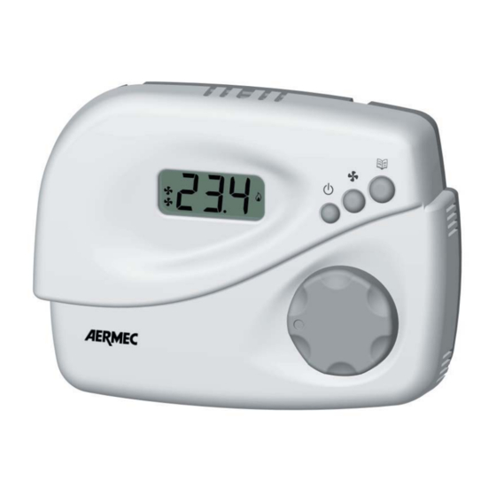
WMT20
TERMOSTATO A DISPLAY PER FAN COIL CON USCITA
37040 Bevilacqua (VR) - Italia
VENTILATORE 0 .. 10V
Via Roma, 996
FAN COIL CONTROLLER WITH DISPLAY AND 0..10V OUTPUT
THERMOSTAT MIT BILDSCHIRM FÜR FAN-COIL MIT AUSGANG FÜR VENTILATOR 0 .. 10V
THERMOSTAT AVEC ECRAN POUR VENTILO-CONVECTEURS
ET SORTIE VENTILATEUR 0 .. 10V
TERMOSTATO CON DISPLAY PARA FAN COIL CON SALIDA VENTILADOR 0 .. 10V
1103
AWMT20UJ
6371600_04
Advertisement
Table of Contents

Summary of Contents for AERMEC WMT20
- Page 1 WMT20 TERMOSTATO A DISPLAY PER FAN COIL CON USCITA 37040 Bevilacqua (VR) - Italia VENTILATORE 0 .. 10V Via Roma, 996 FAN COIL CONTROLLER WITH DISPLAY AND 0..10V OUTPUT THERMOSTAT MIT BILDSCHIRM FÜR FAN-COIL MIT AUSGANG FÜR VENTILATOR 0 .. 10V THERMOSTAT AVEC ECRAN POUR VENTILO-CONVECTEURS ET SORTIE VENTILATEUR 0 ..
- Page 2 GARANZIA Nell’ottica di un continuo sviluppo dei propri prodotti, il costruttore si riserva il diritto di apportare modifiche a dati tecnici e prestazioni senza preavviso. Il consumatore è garantito contro i difetti di conformità del prodotto secondo la Direttiva Europea 1999/44/ nonché...
- Page 3 INSTALLAZIONE / INSTALLATION / AUFSTELLUNG / INSTALLATION / INSTALLACIÓN Fig. 1 - Abb. 1 Fig. 2 - Abb. 2 Fig. 3 - Abb. 3 Fig. 4 - Abb. 4...
- Page 4 SCHEMA DI COLLEGAMENTO / WIRING DIAGRAM / SCHALTSCHEMA / SCHÉMA DE BRANCHEMENT / ESQUEMA DE CONEXIÓN LEGENDA / EXPLANATION / LEGENDE / LÉGENDE / REFERENCIA V FAN: Uscita segnale 0..10V ventilatore / 0..10V fan signal output / Signalausgang 0..10V Ventilator / Sortie signal 0..10V ventilateur / Salida señal 0..10V ventilador SWI: Sonda acqua di mandata / Room sensor / Wasserzulaufsonde / Sonde eau de refoulement / Sonda agua de envío Termostato di minima / Cut-off bimetallic thermostat / Mindestthermostat / Thermostat de minimum / Termostato de mínima...
- Page 5 ATTENZIONE Nel caso di alimentazione del termostato a 24V~ è possibile che tale bassa tensione venga ad essere collegata al neutro 230V~ tramite l’azionamento del motore, in questo caso la 24V~ non si può più considerare bassissima tensione di sicurezza ed è cura dell’installatore garantire un adeguato isolamento.
- Page 6 PILOTAGGIO USCITE / OUTPUT DRIVING / ANSTEUERUNG AUSGÄNGE / PILOTAGE DES SORTIES / PILOTAJE SALIDAS Fig. 7: Lo schema mostra il pilotaggio delle valvole in un impianto a 4 Ts ris Ts raf tubi con zona neutra. Analogamente, l’uscita valvola caldo (OUT HEAT) di un sistema a 2 tubi verrà...
- Page 7 El esquema no tiene en cuenta la eventual acción del tiempo complementario y presupone que la salida proporcional del l ventilador (V FAN) esté configurada para acción directa (P07=0) y señal 0..10V (P33=0; P34=100). La salida proporcional del ventilador se apaga siempre (0V) cuando la salida de la válvula, OUT COOL o OUT HEAT, está apagada (caso non visible en el esquema).
- Page 8 Fig. 8.
- Page 9 Fig. 9.
- Page 10 Fig. 10.
- Page 11 INTRODUCTION Through parameters P30 P31 P32 the user can set the value of the three This digital controller is intended for temperature regulation in environments fi xed speeds. equipped with fan-coil heat-cool exchangers. It controls in continuous - ‘ ‘ Menù key proportional fashion the fan speed with P or P + I algorithm in order to This button is used to change the display readout mode: when depressed adjust the room temperature in the most suitable way.
- Page 12 settings. All temperatures shown must be intended in Celsius degrees In case the controller is configured for remote or automatic heating/cooling (centigrade). selection it is not allowed to enter in the heating/cooling selection menu. On the display there are also some symbols which report about the current INSTALLATION state of the outputs: fan and valves.
- Page 13 extra low voltage (24V~ ) use this voltage also for energising the valves be the installer’s duty to grant a proper insulation. (terminals 2, 3 and 4), thus using 24V~ powered valves, in order not to The device can control either one or two ON/OFF actuators, type NC or NO.
- Page 14 Integrative time: 1 .. 30 min WARNING Neutral zone: 1.0 .. 11.0 °C - The supply water sensor must be installed in a way that it can Impulse voltage rating: acquire the correct water temperature even in case the flow is Action type: stopped by the valve itself.
- Page 15 APPENDIX range. In case the acquired temperature falls outside the operating range mentioned, the display will show the letters ‘Or’ (out of range). In case Supply water sensor input the sensor acts as an open circuit or a short circuit the display will show This controller features an input for a sensor mounted on the water supply the letters ‘EEE’...
- Page 16 set at 0.0 Economy function is actually disabled. Economy saving mode is 10 seconds, until the regulator will confirm to have reset the warning by started from the menu button, as explained in the ‘Operation’ section. In showing again the words FIL-TER. case the remote heating/cooling mode is not configured, terminal 7 can be Temperature regulation used to start the ‘Economy’...
- Page 17 accuracy. (shown in Fig. 3), can be removed; after this any attempt to enter in the The fan is driven in a proportional way except when a fixed speed is set configuration menu will result in an error message. FI1..FI3. With fixed speed, the fan can be only turned off or turned on at Configuration parameters explanation the fixed speed;...
- Page 18 then no automatic selection is performed and the manual switching is only a temperature sensor is expected for the acquisition of water temperature. allowed. When 1 is set, the temperature value is also shown over the display, Remote selection: In a building with several regulators all inputs (terminal according to the user choice.
- Page 19 Actually it could happen that in some installations, due to the sensor disabled. location (either internal or external) the temperature readout is not P19: This parameter defines the hysteresis in °C with which the ON/OFF accurate. outputs are controlled according to the ambient temperature variations. By changing the value of this parameter the display readout can be P20: In case the controller is configured for a neutral zone operation this corrected of the equivalent amount (in the -5.0 ..
- Page 20 P30 P31 P32: These parameters define the speed regimes associated to Room temperature correct acquisition the fixed speeds settings FI1, FI2, FI3, as percentage of the full speed. For a correct temperature acquisition it is mandatory to remember and apply the following tips: P33 and P34: These parameters respectively represent the lower limit - In order to have an accurate room temperature acquisition the controller and the upper limit of the output proportional signal of the fan.
- Page 21 Table 1: Installer configuration (Summary of the parameters involved in the ‘installer’ configuration). System type 2-pipes system 4-pipes system Heating/cooling Reversed Manual Automatic Remote selection remote Heating Valves only Fan only Valves and fan regulation Cooling Valves only Fan only Valves and fan regulation Heating output...
- Page 22 Room temperature Heating proportional correction (offset) (°C) band (°C) Heating set-point knob Cooling proportional lower limit (°C) band (°C) Heating set-point knob Heating integrative upper limit (°C) time (minutes) Cooling set-point knob Cooling integrative lower limit (°C) time (minutes) Cooling set-point knob Fan MIN upper limit (°C) speed (FI1)
Need help?
Do you have a question about the WMT20 and is the answer not in the manual?
Questions and answers