Advertisement
Quick Links
Advertisement

Related Manuals for Blanco BWC9BX


Summary of Contents for Blanco BWC9BX
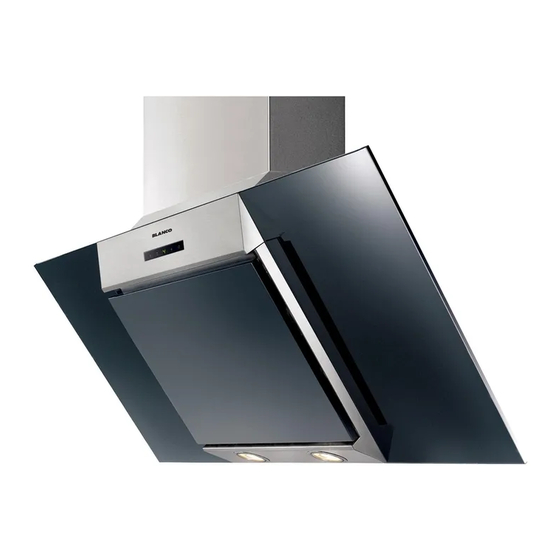
- Page 1 Instructions for the Use and Care and Installation of BWC9BX Rangehood...
- Page 2 Dear Customer You will find that the modern look of your Blanco rangehood blends in perfectly with your kitchen décor. It is easy to use and performs to a high standard. Blanco also makes a range of products that will enhance your kitchen – such as cooktops, ovens, dishwashers, microwaves, sinks and taps.
- Page 3 max 90 cm Fig.1 min 45 cm Fig.3 Fig.2 Fig.4...
- Page 4 Fig.6 Fig.7 Fig. 9A Fig.8 Fig. 9 B Fig. 9 C - 5 -...
- Page 5 Fig. 11 A Fig.10 Fig. 11 C Fig. 11 B Fig. 11 D Fig. 11 E - 6 -...
- Page 6 Fig.13 Fig.12 - 7 -...
-
Page 7: Safety Precaution
65cm. If the instructions for the cooktop specify a greater distance, please consider this. c) The regulations concerning the discharge of exhaust air have to be fulfilled. d) All Blanco rangehoods are used for indoor application/installation only. Other Information: This appliance conforms to the European Directive EC/2002/96, Waste Electrical and Electronic Equipment (WEEE). -
Page 8: Installation Instructions
INSTALLATION INSTRUCTIONS Assembly and electrical connections must be carried out by specialised personnel. • Electric Connection The appliance has been manufactured as a class II, therefore no earth cable is necessary. The connection to the mains is carried out as follows: BROWN = L line BLUE = N neutral If not provided, connect a plug for the electrical load indicated on the description label. -
Page 9: Use And Maintenance
Pull out the top duct as far as the bracket and fix it using screws F (Fig.11C). • RECIRCULATING RANGEHOOD To replace the active carbon filter first remove the aluminium filter by pulling lever B outwards. The filters must then be fitted to the suction inlet of the motor. To fit the filter it must be centred then rotated clockwise 90 degrees to lock (Fig.10). - Page 10 movement of the peripheral segments must be visualised on the display. When this time has passed the motor switches off and the fixed letter “C” must be visualised on the display until the motor re-starts after 50 minutes for another 10 minutes and so on. Press any key apart from the light keys to return to normal functioning.
- Page 11 BWC9BX - 14 -...
Need help?
Do you have a question about the BWC9BX and is the answer not in the manual?
Questions and answers