
Summary of Contents for Gocontrol GC-TBZ48
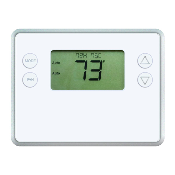
- Page 1 Model GC-TBZ48 Battery Powered Z-Wave Thermostat Installation & Operation Guide MODE Auto...
-
Page 2: Table Of Contents
Table of Contents Typical Wiring for Standard Gas/Electric HVAC System ........2 Typical Wiring for Heat Pump HVAC System . -
Page 3: Installation Instructions
BATTERY POWERED Z-WAVE THERMOSTAT INSTALLATION INSTRUCTIONS The Z-Wave Thermostat (GC-TBZ48) is a programmable, Z-Wave communica ng thermostat. It can be powered using 24VAC (if both “R”&”C”wires are available at the thermostat), or using four (4) AA ba eries. Using Z-Wave technology, end users have the ability to use the 2GIG Go!Control panel to control the thermostat, confi... -
Page 4: Typical Wiring For Standard Gas/Electric Hvac System
Typical Wiring for Standard Gas/Electric HVAC System STANDARD HVAC SYSTEM TYPICAL THERMOSTAT WIRING COLORS. CAUTION: VERIFY THAT ORIGINAL WIRING THERMOSTAT CONNECTION MATCHES. COLORS MAY BE DIFFERENT BLUE C 24VAC COMMON R 24VAC RETURN WHITE W1 HEAT STAGE 1 ORANGE W2 HEAT STAGE 2 G FAN GREEN Y1 COMPRESSOR STAGE 1... -
Page 5: Typical Wiring For Heat Pump Hvac System
Typical Wiring for Heat Pump HVAC System TYPICAL THERMOSTAT WIRING COLORS. CAUTION: VERIFY THAT ORIGINAL WIRING HEAT PUMP HVAC SYSTEM MATCHES. COLORS MAY BE DIFFERENT THERMOSTAT CONNECTION BLUE C 24VAC COMMON R 24VAC RETURN WHITE W1 HEAT STAGE 1 ORANGE O CHANGEOVER VALVE G FAN GREEN... -
Page 6: Thermostat Power
Thermostat Power The thermostat can be powered by either 24VAC from the HVAC system or from four (4) type AA internal ba eries. DO NOT use this thermostat for line voltage controls (120/240VAC). The C Wire If the 24VAC common wire (usually blue) is present and is connected to 24VAC common at the HVAC system end, the thermostat can be powered from the HVAC system and ba eries are not required. -
Page 7: Remove Exis Ng Thermostat
Remove Existing Thermostat • Turn off the power to the thermostat. This is usually done at the hea ng/cooling system or circuit breaker panel. • Remove the cover of old thermostat to expose the wiring terminals. • Take a picture of the wiring terminals and the wires before disconnecting them! •... -
Page 8: Install The Back Panel
Install the Back Panel Remove the back panel of the thermostat by pushing down the thumb tab on the bo om of the body. Figure 3. Removing back panel of thermostat. BACK PANEL BODY (WITH PCB) PUSH ON THUMB TAB TO RELEASE BACK PANEL Mount the thermostat back panel on the wall (See Figure 4). -
Page 9: Standard Hvac System Connec Ons
Standard HVAC System Connections NOTE: For typical connec ons to a Standard HVAC system, refer to the diagram on Page 2. The terminals on the back panel have two sets of labels. The upper label shows the STANDARD HVAC terminal connec ons. The lower label shows HEAT PUMP HVAC terminal connec ons. Figure 5. -
Page 10: Dual Transformer Systems
Dual Transformer Systems For HVAC systems that have separate hea ng and cooling systems, each with their own 24VAC transformers, there will be an “R” wire from the hea ng system and an “R” wire from the cooling system. For dual transformer systems, connect the “C” wire from the cooling system to the thermostat’s “C” terminal. -
Page 11: Heat Pump Hvac System Connec Ons
Heat Pump HVAC System Connections NOTE: For typical connec ons to a Heat Pump HVAC system, refer to the diagram on Page 3. The terminals on the back panel have two sets of labels. The lower label shows HEAT PUMP HVAC terminal connec ons. -
Page 12: Mount The Thermostat
Mount the Thermostat Install the thermostat body/front panel onto the wall mounted base by fi rmly pressing in place un l it snaps all around the edges. The GC-TBZ48 is now ready to program. Figure 11. Attaching Front Panel to Back Panel... -
Page 13: Thermostat Setup Menus
Thermostat Setup Menus The thermostat must be setup for the correct HVAC system type for proper opera on. Preset HVAC System se ngs The thermostat is preset for the following typical HVAC system confi gura on: • HVAC system type: Standard gas/electric •... -
Page 14: Entering Menu Mode
Entering Menu Mode To change the System setup, go to the thermostats Menu Mode and select SYSTEM. From there select the correct HVAC se ngs to match the installa on type. Press and hold the FAN bu on to enter the Menu Mode. SETUP is the fi rst menu item displayed. Press the M bu on to advance to the SYSTEM screen. -
Page 15: System Menu
System Menu The SYSTEM menu is used to setup the thermostat for the correct HVAC system type. The following setup op ons will be displayed in the text line: • HVAC System Type: Standard Gas/Electric or Heat Pump • Fan Type: Gas Hea ng or Electric Hea ng •... -
Page 16: Z-Wave Installa On
Z-Wave Installa on Z-Wave controllers from various manufacturers may support the Z-Wave Thermostat General V2 Device class used by the Go Control Z-WAVE Thermostat. The following procedure will allow the thermostat to be added to a Z-Wave network. NOTE: Before adding the thermostat to a Z-Wave Network, check that it does not already belong to one by viewing the Node ID (ZNID) located in the Thermostat Info screen. -
Page 17: Clock Menu
INFO Menu The INFO menu displays informa on about the thermostat. Use the LM bu ons to scroll through the various items. • MODEL GC-TBZ48 • VERSION Thermostat fi rmware version. • ZWAVE Z-Wave fi rmware version. • NODE ID Z-Wave Node ID. -
Page 18: Advanced System Se Ngs Menu
Advanced System Se ngs Menu The Advanced System Se ngs Menu provides for addi on system setup op ons. These se ngs can aff ect system opera on and should only be changed by qualifi ed HVAC installers. To access the Advanced System Se ngs menu, fi rst press and hold the FAN bu on to get into the Setup menu. - Page 19 Default Feature Description Range Setting Heat - Cool Sets the minimum separa on between hea ng 3 to 15 3F (1C) Delta and cooling setpoints. NOTE: Attempts to lower degrees cooling setpoint below the heating setpoint will PUSH the heating setpoint down to maintain this separation.
-
Page 20: Thermostat Opera On
Thermostat Operation Main Thermostat Screen Figure 18. Main Screen TEMPERATURE SETPOINT HEATING/COOLING MODE SELECTION WARMER MODE Auto COOLER FAN MODE SELECTION ROOM TEMPERATURE BACKLIT DISPLAY Backlight and Bu on Opera on The thermostat backlight is normally set to go out a er 20 seconds of no bu on presses to conserve ba ery power. -
Page 21: Se Ng The System Mode
Se ng the System Mode Figure 20 Setting the System Mode PRESS MODE BUTTON TO MODE CHANGE SYSTEM MODE Auto System Modes • Off: System is off . No hea ng or cooling will come on. If system was on, it will turn off immediately. -
Page 22: Se Ng The Hea Ng Or Cooling Temperature Setpoint
Se ng the Hea ng or Cooling Temperature Setpoint To change the setpoint, press the LM bu ons. The screen will switch to the setpoint change screen and show the current setpoint of the current hea ng or cooling mode. Adjust the setpoint temperature up or down with the LM bu ons. -
Page 23: Se Ng The Fan Mode
Se ng the Fan Mode Figure 23. Fan Setting MODE Auto PRESS FAN FOR ON OR AUTOMATIC MODE Fan Modes Use the FAN bu on to select the HVAC system’s fan mode. • Auto: Fan automa cally operated by the HVAC system (normal se ng). •... -
Page 24: User Customiza On
User Customiza on Figure 24. Selecting Menu Mode TO SELECT THE MODE MENU MODE, PRESS AND HOLD THE FAN Auto BUTTON UNTIL THE SETUP SCREEN IS DISPLAYED Figure 25. Menu Navigation MENU CHOICES ARE DISPLAYED IN THE STATUS DISPLAY LINE PRESS SELECT TO ENTER THE DISPLAYED USE THE LM... -
Page 25: Clock Menu
Clock Menu Use the clock menu to set thermostat’s internal clock. Figure 26. Clock Setup MENU CHOICES ARE DISPLAYED IN THE STATUS DISPLAY LINE USE THE LM Select MODE BUTTONS TO CHANGE TO THE DESIRED MENU PUSH AND HOLD Done ITEM, THEN PRESS FOR 5 SECONDS SELECT... -
Page 26: Specifi Ca Ons
Specifications C-Wire Input: 20-30VAC Power Ba ery Power: 4 AA Ba eries 32° to 120°F (0° to 49°C) Operating Temperature -40° to 140°F (-40° to 60°C) Storage Temperature 7 character alpha numeric display, with message scroll Messaging Capability 1° F (0.5°C), Calibrates to +/- 7°F Set-point Accuracy 1°... -
Page 27: Regulatory Informa On
Regulatory Information FCC ID: WIBTZW011 This device complies with Part 15 of the FCC Rules. Opera on is subject to the following two condi ons: (1) This device may not cause harmful interference, and (2) This device must accept any interference received, including interference that may cause undesired opera on. - Page 28 Go Control 1950 Camino Vida Roble, Suite 150 Carlsbad, CA 92008 USA For technical support in the USA and Canada: Dial: 855-2GIG-TECH (855-244-4832) Email : 2gigtechsupport@nortek.com Visit website for technical support hours of operation For technical support outside of the USA and Canada: Contact your regional distributor Visit www.2GIG.com or dealer.2gig.com technical support hours of operation 10006516 A...
Need help?
Do you have a question about the GC-TBZ48 and is the answer not in the manual?
Questions and answers
Can you set different temperature settings during the day. Example - At 8:00pm setting to 73 degrees and at 6:00am setting to 78 degrees?