Sign In
Upload
Manuals
Brands
Zeiss Manuals
Microscope
Axio Vert.A1
Zeiss Axio Vert.A1 Manuals
Manuals and User Guides for Zeiss Axio Vert.A1. We have
1
Zeiss Axio Vert.A1 manual available for free PDF download: Operating Manual
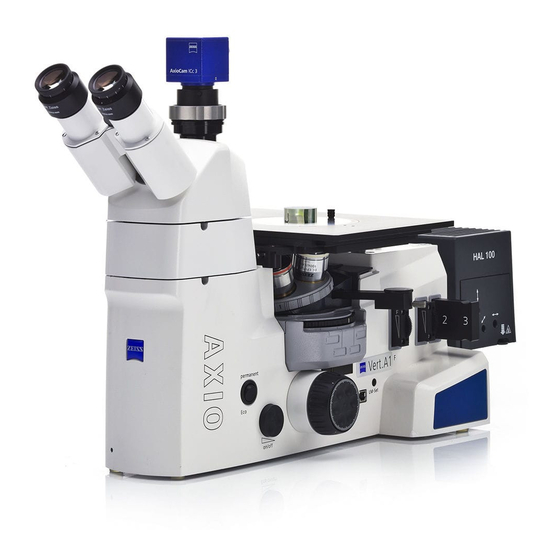
Zeiss Axio Vert.A1 Operating Manual (106 pages)
Inverted Microscope
Brand:
Zeiss
| Category:
Microscope
| Size: 6.3 MB
Table of Contents
Table of Contents
3
1 Introduction
8
Notes on Instrument Safety
8
Nameplate and Warning Labels Attached to the Microscope and to Components
11
Fig. 1-1 Nameplate on the Axio Vert.a1 FL Stand and Warning Labels on the LED Illuminator for Transmitted Light
11
Fig. 1-2 Warning Labels on the Axio Vert.a1 FL-LED Stand
12
Fig. 1-3 Warning Labels on the VIS-LED (423053-9030-000)
12
Notes on Warranty
13
Types of Stands (General Views)
14
2 Instrument Description
15
Name, Intended Use
15
Instrument Description and Main Features
16
System Overview
18
Stands for Biomed Applications
18
Fig. 2-1 Axio Vert.a1 System Overview (Biomed Stands)
18
Fig. 2-2 Axio Vert.a1 System Overview (Biomed Stands)
19
Fig. 2-3 Axio Vert.a1 System Overview (Biomed Stands)
20
Stand for Material Applications
21
Fig. 2-4 Axio Vert.a1 System Overview (Material Stand)
21
Fig. 2-5 Axio Vert.a1 System Overview (Material Stand)
22
Technical Specifications
23
Operation and Functional Elements on the Microscope
26
Axio Vert.a1 Stand for Transmitted Light
26
Fig. 2-6 Axio Vert.a1
27
Axio Vert.a1 FL Stand for Reflected Light and Transmitted Light Fluorescence
28
Fig. 2-7 Axio Vert.a1 FL
29
Axio Vert.a1 FL-LED Stand for Transmitted Light and Reflected Light LED Fluorescence
30
Fig. 2-8 Axio Vert.a1 FL-LED
31
Axio Vert.a1 MAT Stand for Reflected Light (Material)
32
Fig. 2-9 Axio Vert.a1 MAT
33
Operation and Functional Elements of Optional Components
34
Phototube and Intermediate Phototube
34
Fig. 2-10 Binocular Phototube 45°/23 and Binocular Phototube, Left, 45°/23
34
Fig. 2-11 Intermediate Phototube, Left, with Exchangeable Mirror
34
Fig. 2-12 Adjusting the Viewing Height on the Binocular Tube
35
Fig. 2-13 Binocular Ergophototube 30°-60°/23
35
Microscope Stages
36
Fig. 2-14 Mechanical Stage 130X85 R with Mounting Frame
36
Fig. 2-15 Specimen Stage 232X230 and Object Guide M 130X85 MM
36
Fig. 2-16 Mechanical Stage 40X40 for Reflected Light with Stage Insert
36
Condensers
37
Fig. 2-17 LD Condensers 0.3 and 0.4 for Sliders
37
Fig. 2-18 LD Condenser 0.4 for H Ph Plasdic DIC Ihmc with Insertable Polarizer Slider DL, Rotatable 90 Degrees
37
Objective Nosepiece with Objectives
38
Fig. 2-19 LD Condenser 0.55 for H Ph Plasdic DIC
38
Fig. 2-20 Five-Position Objective Nosepiece
38
Filter Slider and Slider for Aperture and Luminous Light Diaphragms for the Axio Vert.a1 MAT and Axio Vert.a1 FL Stands
39
Filter Slider Mounted on the Carrier for Transmitted Light Illumination
39
Fig. 2-21 Reflected Light Filter Slider and Slider for Aperture and Luminous Field Diaphragms
39
Fig. 2-22 Transmitted Light Filter Slider
39
3 Putting the Instrument into Operation
40
Mounting Standard Components
40
Microscope Unpacking and Setup
40
Attaching the Binocular (Photo)Tube
41
Fig. 3-1 Unpacking and Setup
41
Fig. 3-2 Attaching the Binocular Tube
41
Inserting Eyepieces or an Auxiliary Microscope or a Diopter
42
Inserting an Eyepiece Reticle
42
Fig. 3-3 Inserting Eyepieces
42
Fig. 3-4 Inserting an Eyepiece Reticle
42
Screwing Objectives in Place
43
Fig. 3-5 Screwing Objectives in Place
43
Attaching Microscope Stages
44
Fig. 3-6 Mounting the Mechanical Stage (Shown Without Tube)
44
Fig. 3-7 Mounting the Specimen Stage
44
Fig. 3-8 Underside of the Scanning Stage
45
Fig. 3-9 Upper Side of the Scanning Stage
45
Fig. 3-10 Terminals on the Underside of the Scanning Stage
46
Inserting, Rotating and Shifting a Condenser
47
Fig. 3-11 Inserting the Condenser
47
Inserting Stop Sliders into Condensers 0.3 or 0.4 for Sliders
48
Equipping the Reflector Turret
49
Fig. 3-12 Equipping the Reflector Turret
49
Attaching Transmitted Light Illumination
50
Fig. 3-13 Attaching the HAL Illuminator
50
Fig. 3-14 Changing the Halogen Lamp for Transmitted Light
51
Attaching Illuminators for Reflected Light
52
Fig. 3-15 Attaching the LED Illuminator
52
Fig. 3-16 Attaching the HBO 50 Illuminator or the HBO 100 Illuminator
53
Fig. 3-17 Adjusting HBO 50
54
Fig. 3-18 Adjusting HBO 100
55
Fig. 3-19 Attaching the VIS-LED Illuminator
56
Fig. 3-20 Adjusting the VIS-LED Attachment Illuminator
56
Fig. 3-21 Attaching the HAL 100 Illuminator
57
Adjusting the HAL 100 Illuminator
58
Fig. 3-22 Adjusting the HAL 100 Illuminator
58
Changing the HAL 100 Halogen Lamp
59
Fig. 3-23 Changing the Halogen Lamp
59
Connecting the Microscope to the Power Supply System, Switching the Microscope on and Setting It up
60
Fig. 3-24 Connecting and Switching on the Microscope
60
Mounting Optional Components
61
Changing Diaphragms in the Condenser with Modulator Disk
61
Fig. 3-25 Installing Diaphragms in the Modulator Disk of the Condenser
61
Changing Diaphragms in Sliders
63
Fig. 3-26 Inserting and Changing Diaphragms in the Slider
63
Fig. 3-27 Orienting the Slit Diaphragm in the Slider as a Function of the Position to the
63
Microscope Axis
63
Changing the Filter Set in the FL P&C Reflector Module
64
Fig. 3-28 Changing a Filter Set in the FL P&C Reflector Module
64
Changing the Beam Splitter in the FL P&C Reflector Module
65
Fig. 3-29 Installing Filters and Beam Splitters
65
Fig. 3-30 Opening the Reflector Module
65
Fig. 3-31 Changing the Beam Splitter
66
Fig. 3-32 Identification Features of the Beam Splitter
66
Changing the Beam-Splitting Mirror in the Intermediate Phototube
67
Fig. 3-33 Changing the Beam-Splitting Mirror in the Intermediate Phototube
67
Mounting the Aqua Stop
68
Fig. 3-34 Mounting the Aqua Stop
68
Changing LED Modules in the Axio Vert.a1 FL-LED Stand
69
Fig. 3-35 Changing the LED Module in the Axio Vert.a1 FL-LED Stand
69
Mounting the Carrier for Transmitted Light Illumination Onto the Axio Vert.a1 MAT Stand
70
Fig. 3-36 Mounting the Carrier for Transmitted Light Illumination
70
4 Operation
71
Use of LD Objectives
71
Use of Korr Objectives
71
Fig. 3-37 Working with LD Objectives
71
Use of Immersion Objectives
72
Possible Condenser, Objective and Diffusion Disk Combinations
72
Use of Objectives
73
ECO Power-Saving Function
73
Height Stop for the Focusing Drive
74
Operating Functions on the Axio Vert.a1 FL-LED Stand
74
Fig. 4-1 Height Stop of the Focusing Drive
74
Light Manager Function on the Axio Vert.a1 MAT Stand
75
USB Interface on the Axio Vert.a1 MAT Stand
75
Illumination and Contrast Techniques in Transmitted Light
76
Transmitted Light Bright Field
76
Fig. 4-2 Setting Bright Field
76
Transmitted Light Phase Contrast
77
Fig. 4-3 Setting Phase Contrast
77
Fig. 4-4 Centering the Phase Ring Diaphragm (Bright in the Condenser) to the Phase Ring (Dark in the Objective)
77
Transmitted Light VAREL Contrast
79
Fig. 4-5 Setting VAREL Contrast
79
Fig. 4-6 VAREL Contrast for Microtiter Plates
79
Transmitted Light Differential Interference Contrast (DIC)
80
Fig. 4-7 VAREL Contrast Pupil Images
80
Fig. 4-8 Setting DIC
81
Transmitted Light Plasdic
82
Transmitted Light Ihmc
83
Fig. 4-10 Centering Screws
84
Fig. 4-11 Aligning of the Objective Zone Plate and the Ihm Diaphragm
85
Transmitted Light Polarization Contrast
86
Fig. 4-12 Setting Bright Field
86
Illumination and Contrast Techniques in Reflected Light
87
Reflected Light Bright Field
87
Fig. 4-14 Setting Bright Field
88
Reflected Light Dark Field
89
Reflected Light DIC
90
Reflected Light Polarization
92
Fig. 4-16 Setting the Polarization
93
Reflected Light Fluorescence
94
Fig. 4-17 Setting Fluorescence
95
Micromanipulators
96
5 Care, Maintenance, Troubleshooting and Service
97
Care
97
Maintenance
98
Performing Checks
98
Replacing Fuses on the Microscope
98
Service
99
6 Annex
100
List of Abbreviations
100
Keyword Index
101
Property Rights
105
Advertisement
Advertisement
Related Products
Zeiss VISU 200
Zeiss OPMI VISU 160
Zeiss VivaTome
Zeiss Axioplan 2 imaging and Axiophot 2
Zeiss Axiovert 100
Zeiss Axiovert 135
Zeiss Axiovert 135M
Zeiss Axioskop
Zeiss Axiolab Pol
Zeiss Axiovert 200
Zeiss Categories
Microscope
Medical Equipment
Binoculars
Laboratory Equipment
Measuring Instruments
More Zeiss Manuals
Login
Sign In
OR
Sign in with Facebook
Sign in with Google
Upload manual
Upload from disk
Upload from URL