Sign In
Upload
Manuals
Brands
YASKAWA Manuals
Amplifier
SGDS Sigma III Series
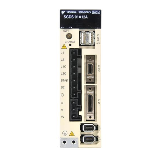
YASKAWA SGDS Sigma III Series Manuals
Manuals and User Guides for YASKAWA SGDS Sigma III Series. We have
1
YASKAWA SGDS Sigma III Series manual available for free PDF download: User Manual
YASKAWA SGDS Sigma III Series User Manual (376 pages)
Servo Amplifier for Mechatrolink-II Communications
Brand:
YASKAWA
| Category:
Amplifier
| Size: 5.98 MB
Table of Contents
Table of Contents
14
1 Outline
23
Checking Products
23
Check Items
23
Servomotors
23
Servo Amplifiers
24
Product Part Names
24
Servomotors
24
Model Numbers
25
Standard Servomotors
25
Servo Amplifiers
26
Examples of Servo System Configurations
27
Applicable Standards
31
North American Safety Standards (UL, CSA)
31
CE Marking
31
2 System Selection
33
Servomotor Model Designations
33
Model SGMAH/SGMPH/SGMSH
33
Model SGMCS
35
SERVOPACK Model Designations
36
Σ III Series Servopacks and Applicable Servomotors
37
Selecting Cables
38
Cables for SGMAH and SGMPH Servomotors
38
Cables for SGMSH Servomotor
43
Cables for SGMGH Servomotors
47
Cables for SGMCS Servomotor
51
Selecting Peripheral Devices
54
Special Options
54
Molded-Case Circuit Breaker and Fuse Capacity
56
Noise Filters, Magnetic Contactors, Surge Protectors and AC/DC Reactors
57
Regenerative Resistors
58
3 SERVOPACK Specifications and Dimensional Drawings
61
SERVOPACK Ratings and Specifications
61
SERVOPACK Installation
64
SERVOPACK Internal Block Diagrams
66
Single-Phase 100 V, 50 W to 400 W
66
Single-Phase 200 V, 50 W to 400 W
67
Three-Phase 200
68
Three-Phase 200 V, 1.0 Kw
68
Single-Phase 200 V 800 W
69
Three-Phase 200 V, 3.0~5.0Kw
70
SERVOPACK Power Supply Capacities and Power Losses
71
SERVOPACK Overload Characteristics and Load Moment of
72
Inertia
72
Overload Characteristics
72
Starting and Stopping Time
72
SERVOPACK Overload Characteristics and Load Moment
72
Load Moment of Inertia
73
SERVOPACK Dimensional Drawings
79
Dimensional Drawings of Base-Mounted SERVOPACK Model SGDS- 12A / - 12A
80
Single-Phase 100 V/200 V, 50 W/100 W/200 W
80
Single-Phase 100 V, 400 W
80
Single-Phase 200 V, 400 W
81
Single-Phase 200 V, 800 W, Three-Phase 200 V, 1.0 Kw
81
4 Specifications and Dimensional Drawings of Cables and Peripheral Devices
84
SERVOPACK Main Circuit Wire Size
85
Connectors for Main Circuit, Control Power Supply, and Servomotor Cable
87
Spring Type (Standard)
87
Crimp Type (Option)
88
CN1 Cables for I/O Signals
90
Connector Type and Cable Size
90
Peripheral Devices
91
Digital Operator
91
Cables for Analog Monitor
91
External Regenerative Resistor
92
Absolute Encoder Battery
94
Molded-Case Circuit Braker (MCCB)
95
Noise Filter
96
Magnetic Contactor
99
Surge Protector
100
AC/DC Reactors for Power Supplied Designed for Minimum Harmonics
101
MECHATROLINK/MECHATROLINK II Communication Cable
102
MECHATROLINK/MECHATROLINK II Terminator
102
Cable with Connectors at both Ends for Fully-Closed Control
103
Serial Converter Unit for Fully-Closed Control
103
5 Wiring
107
Wiring Main Circuit
107
Names and Descriptions of Main Circuit Terminals
107
Wiring Main Circuit Terminal Block (Spring Type)
108
Typical Main Circuit Wiring Examples
109
Wiring Encoders
112
Connecting an Encoder
112
CN2 Encoder Connector Terminal Layout
113
I/O Signal Connections
114
Connection Example of I/O Signal
114
I/O Signal Connector (CN1) Terminal Layout
115
I/O Signal (CN1) Names and Functions
115
Interface Circuit
116
Wiring MECHATROLINK II Communications
118
Wiring Example MECHATROLINK II Communications
118
MECHATROLINK II Communications Connectors (CN6A, CN6B)
119
Precautions for Wiring MECHATROLINK II Cables
119
Fully-Closed Encoder Connections
121
Connection Example of Linear Scale by Heidenhain
121
Connection Example of Linear Scale by Renishaw
122
Others
123
Wiring Precautions
123
Wiring for Noise Control
124
Wiring for Noise Control
125
Using more than One SERVOPACK
127
Power Supply Voltage
128
AC/DC Reactor for Harmonic Suppression
129
Connecting Regenerative Resistors
130
Regenerative Power and Regenerative Resistance
130
Connecting Externally Regenerative Resistors
130
6 MECHATROLINK II Communications
134
Specifications and Configuration
136
Specifications
136
System Configuration
136
Switches for MECHATROLINK II Communications Settings
137
Communications Settings
137
Setting the Transmission Cycle
137
Setting the Station Address
138
Main Commands
139
No Operation (NOP: 00H)
139
Read Parameter (PRM_RD: 01H)
140
Write Parameter (PRM_WR: 02H)
141
Read ID (ID_RD: 03H)
142
Set up Device (CONFIG: 04H)
143
Read Alarm or Warning (ALM_RD: 05H)
144
Clear Alarm or Warning (ALM_CLR: 06H)
146
Start Synchronous Communications (SYNC_SET: 0DH)
147
MECHATROLINK II Connection (CONNECT: 0EH)
148
Disconnection (DISCONNECT: 0FH)
149
Read Non-Volatile Parameter (PPRM_RD: 1BH)
150
Write Non-Volatile Parameter (PPRM_WR: 1CH)
151
Set Coordinates (POS_SET: 20H)
152
Apply Brake (BRK_ON: 21H)
153
Release Brake (BRK_OFF: 22H)
154
Turn Sensor on (SENS_ON: 23H)
155
Turn Sensor off (SENS_OFF: 24H)
156
Stop Motion (HOLD: 25H)
157
Request Latch Mode (LTMOD_ON: 28H)
158
Release Latch Mode (LTMOD_OFF: 29H)
159
Status Monitoring (SMON: 30H)
160
Servo on (SV_ON: 31H)
161
Servo off (SV_OFF: 32H)
162
Interpolation Feed (INTERPOLATE: 34H)
163
Positioning (POSING: 35H)
164
Constant Speed Feed (FEED: 36H)
165
Interpolation Feeding with Position Detection (LATCH: 38H)
166
External Input Positioning (EX_POSING: 39H)
167
Homing (ZRET: 3AH)
169
Velocity Control (VELCTRL: 3CH)
171
Torque Control (TRQCTRL: 3DH)
172
Adjusting (ADJ: 3EH)
173
General-Purpose Servo Control (SVCTRL: 3FH)
174
MECHATROLINK Connection (CONNECT: 0EH)
176
Subcommands
177
No Operation (NOP: 00H)
177
Read Parameter (PRM_RD: 01H)
177
Write Parameter (PRM_WR: 02H)
178
Read Alarm or Warning (ALM_RD: 05H)
178
Read Non-Volatile Parameter (PPRM_RD: 1CH)
179
Write Non-Volatile Parameter (PPRM_WR: 1CH)
179
Request Latch Mode (LTMOD_ON: 28H)
180
Release Latch Mode (LTMOD_OFF: 29H)
180
Status Monitoring (SMON: 30H)
181
Command Data Field
182
Option Field Specifications: OPTION
183
Status Field Specifications: STATUS
184
Monitor Selection and Monitor Information Field Specifications: SEL_MON1/2/3/4, MONITOR1/2/3/4
185
IO Monitor Field Specifications: IO_MON
186
Substatus Field Specifications: SUBSTATUS
187
Command and Response Timing
188
Command Data Execution Timing
188
Monitor Data Input Timing
188
Operation Sequence
189
Operation Sequence for Managing Parameters Using a Controller
189
Operation Sequence for Managing Parameters Using SERVOPACK
190
Operation Sequence When Being Servo on
191
Operation Sequence at Emergency Stop (Main Circuit OFF)
191
Operation Sequence When OT (Overtravel Limit Switch) Signal Is Input
191
7 Operation
192
Outline
193
Before Reading this Chapter
193
Parameter Configurations
193
Digits with Allocated Functions in Parameter
194
Trial Operation
195
Check Items before Trial Operation
195
Trial Operation for MECHATROLINK II Communications
195
Trial Operation Inspection
196
Supplementary Information on Trial Operation
197
Settings According to Machine Characteristics
199
Switching Servomotor Rotation Direction
199
Setting the Overtravel Limit Function
199
Setting the Overtravel Limit Function
201
Software Limit Settings
202
Settings According to Host Controller
204
Sequence I/O Signals
204
Using the Electronic Gear Function
205
Acceleration/Deceleration Function
209
Motion Settings
212
Setting up the SERVOPACK
214
Parameters
214
Input Circuit Signal Allocation
214
Input Circuit Signal Allocation
215
Output Circuit Signal Allocation
217
Debug Function
219
Monitoring
219
Setting Stop Functions
220
Using the Dynamic Brake
220
Using the Holding Brake
221
Absolute Encoders
224
Selecting an Absolute Encoder
224
Absolute Encoder Setup
224
Multi-Turn Limit Setting
226
Multi-Turn Limit Setting
227
Absolute Encoder Home Position Offset
228
8 Adjustments
230
Autotuning
232
Servo Gain Adjustment Methods
232
List of Servo Adjustment Functions
233
Normal Autotuning
236
Normal Autotuning Procedure
236
Normal Autotuning Procedure
237
Selecting the Normal Autotuning Execution Method
238
Machine Rigidity Setting for Normal Autotuning
239
Method for Changing the Machine Rigidity Setting
240
Procedure for Saving the Results of Normal Autotuning
241
Saving the Results of Normal Autotuning
241
Advanced Autotuning
242
Advanced Autotuning Procedure
242
Advanced Autotuning Procedure
244
One-Parameter Autotuning
247
One-Parameter Autotuning Procedure
247
Manual Tuning
249
Explanation of Servo Gain
249
Servo Gain Manual Tuning
249
Position Loop Gain
250
Servo Gain Manual Tuning
250
Speed Loop Gain
251
Speed Loop Integral Time Constant
251
Servo Gain Adjustment Functions
252
Feed Forward Reference
252
Using the Mode Switch (P/PI Switching)
253
Setting the Speed Bias
257
Speed Feedback Filter Time Constant
257
Speed Feedback Compensation
257
Switching Gain Settings
259
Predictive Control
264
Less Deviation Control
269
Torque Reference Filter
275
Vibration Suppression on Stopping
277
Backlash Compensation
278
Position Integral
278
Analog Monitor
279
Analog Monitor
280
9 Fully-Closed Control
283
Control
283
System Configuration for SERVOPACK with Fully-Closed Control
283
Serial Converter Unit
284
Specifications
284
Analog Signal Input Timing
285
Connection Example of Linear Scale by Heidenhain
286
Connection Example of Linear Scale by Renishaw
287
Connection Cable between SERVOPACK and Serial Converter Unit
288
Internal Configuration of Fully-Closed Control
289
Related Parameters
290
10 Inspection, Maintenance, and Troubleshooting
292
Troubleshooting
292
Status Display on Panel Operator
293
Troubleshooting
293
Alarm Display Table
294
Warning Displays
297
Troubleshooting of Alarm and Warning
298
Troubleshooting for Malfunction Without Alarm Display
312
Inspection and Maintenance
316
Servomotor Inspection
316
SERVOPACK Inspection
316
Servopack's Parts Replacement Schedule
317
11 Appendix
318
Servomotor Capacity Selection Examples
319
Selection Example for Speed Control
319
Selection Example for Position Control
321
Calculating the Required Capacity of Regenerative Resistors
323
List of Parameters
328
Utility Functions List
328
List of Parameters
329
Monitor Modes
354
Using the Adjusting Command (ADJ: 3EH)
355
Autotuning
355
Absolute Encoder Setup (Initialization)
360
Multi-Turn Limit Setting
361
Automatic Offset Adjustment of Motor Current Detection Signals
362
Parameter Recording Table
363
Index
375
Advertisement
Advertisement
Related Products
YASKAWA SIGMA 5
YASKAWA SGDS-***12A Series
YASKAWA SGDG-01GT
YASKAWA SGDG-04GT
YASKAWA SGDG-10GT
YASKAWA SGDG-15GT
YASKAWA SGD Series
YASKAWA SGDS-A Series
YASKAWA SGDS-F Series
YASKAWA SGDS-B Series
YASKAWA Categories
Controller
DC Drives
Servo Drives
Robotics
Control Unit
More YASKAWA Manuals
Login
Sign In
OR
Sign in with Facebook
Sign in with Google
Upload manual
Upload from disk
Upload from URL