Table of Contents
Advertisement
Quick Links
DATASHEET
YASKAWA
SGDS-08A01A
OTHER SYMBOLS:
SGDS08A01A, SGDS 08A01A, SGDS-08A01A
RGB ELEKTRONIKA AGACIAK CIACIEK
SPÓŁKA JAWNA
Jana Dlugosza 2-6 Street
51-162 Wrocław
Poland
biuro@rgbelektronika.pl
+48 71 325 15 05
www.rgbautomatyka.pl
www.rgbelektronika.pl
www.rgbelektronika.pl
www.rgbautomatyka.pl
Advertisement
Table of Contents
Troubleshooting

Related Manuals for YASKAWA SGDS Sigma III Series


Summary of Contents for YASKAWA SGDS Sigma III Series
- Page 1 DATASHEET YASKAWA SGDS-08A01A OTHER SYMBOLS: SGDS08A01A, SGDS 08A01A, SGDS-08A01A RGB ELEKTRONIKA AGACIAK CIACIEK SPÓŁKA JAWNA Jana Dlugosza 2-6 Street 51-162 Wrocław www.rgbelektronika.pl Poland biuro@rgbelektronika.pl +48 71 325 15 05 www.rgbautomatyka.pl www.rgbautomatyka.pl www.rgbelektronika.pl...
- Page 2 YOUR PARTNER IN MAINTENANCE Repair this product with RGB ELEKTRONIKA ORDER A DIAGNOSIS LINEAR ENCODERS SYSTEMS INDUSTRIAL COMPUTERS ENCODERS CONTROLS SERVO AMPLIFIERS MOTORS MACHINES OUR SERVICES POWER SUPPLIERS OPERATOR SERVO PANELS DRIVERS At our premises in Wrocław, we have a fully equipped servicing facility. Here we perform all the repair works and test each later sold unit.
- Page 3 SGDS Sigma III Servo Amplifier User Manual for Mechatrolink-II Communications...
- Page 4 Yaskawa. No patent liability is assumed with respect to the use of the information contained herein. Moreover, because Yaskawa is constantly striving to improve its high-quality products, the information contained in this manual is subject to change without notice.
- Page 5 About this Manual Description of Technical Terms The terms in this manual are defined as follows: • Servomotor or motor = Σ II Series SGMAH, SGMPH, SGMSH, SGMCS (direct drive) servomotor. • SERVOPACK = Σ ΙΙΙ Series SGDS SERVOPACK with MECHATROLINK II interface. •...
- Page 6 ■ Visual Aids The following aids are used to indicate certain types of information for easier reference. • Indicates important information that should be memorized, including precautions such as alarm IMPORTANT displays, to avoid damaging the devices. • Indicates supplemental information. INFO •...
- Page 7 The warning symbols for ISO and JIS standards are different, as shown below. The ISO symbol is used in this manual. Both of these symbols appear on warning labels on Yaskawa products. Please abide by these warning labels regardless of which symbol is used.
- Page 8 Notes for Safe Operation Read this manual thoroughly before checking products on delivery, storage and transportation, installation, wiring, operation and inspection, and disposal of the AC servo drives. WARNING • Never touch any rotating motor parts while the motor is running. Failure to observe this warning may result in injury.
- Page 9 WARNING • Installation, disassembly, or repair must be performed only by authorized personnel. Failure to observe this warning may result in electric shock or injury. • Do not modify the product. Failure to observe this warning may result in injury or damage to the product. Checking on Delivery CAUTION •...
- Page 10 Installation CAUTION • Never use the products in an environment subject to water, corrosive gases, inflammable gases, or combustibles. Failure to observe this caution may result in electric shock or fire. • Do not step on or place a heavy object on the product. Failure to observe this caution may result in injury.
- Page 11 Wiring CAUTION • Do not connect a three-phase power supply to the U, V, or W output terminals. Failure to observe this caution may result in injury or fire. • Securely connect the power supply terminal screws and motor output terminal screws. Failure to observe this caution may result in fire.
- Page 12 CAUTION • Take appropriate and sufficient countermeasures for each when installing systems in the following locations. • Locations subject to static electricity or other forms of noise. • Locations subject to strong electromagnetic fields and magnetic fields. • Locations subject to possible exposure to radioactivity. •...
- Page 13 When this manual is revised, the manual code is updated and the new manual is published as a next edition. • If the manual must be ordered due to loss or damage, inform your nearest Yaskawa representative or one of the offices listed on the back of this manual.
-
Page 14: Table Of Contents
CONTENTS 1 Outline 1.1 Checking Products - - - - - - - - - - - - - - - - - - - - - - - - - - - - - - 1-2 1.1.1 Check Items - - - - - - - - - - - - - - - - - - - - - - - - - - - - - - - - - - - - - - - - - 1-2 1.1.2 Servomotors - - - - - - - - - - - - - - - - - - - - - - - - - - - - - - - - - - - - - - - - - 1-2 1.1.3 Servo Amplifiers - - - - - - - - - - - - - - - - - - - - - - - - - - - - - - - - - - - - - - 1-3 1.2 Product Part Names - - - - - - - - - - - - - - - - - - - - - - - - - - - - - 1-3... - Page 15 3.3.3 Three-phase 200 V, 1.0 kW - - - - - - - - - - - - - - - - - - - - - - - - - - - - - - -3-9 3.3.4 Single-phase 200 V 800 W - - - - - - - - - - - - - - - - - - - - - - - - - - - - - - 3-10 3.3.5 Three-phase 200 V, 3.0~5.0kW - - - - - - - - - - - - - - - - - - - - - - - - - - - 3-11 3.4 SERVOPACK Power Supply Capacities and Power Losses 3-12 3.5 SERVOPACK Overload Characteristics and Load Moment of...
- Page 16 5 Wiring 5.1 Wiring Main Circuit - - - - - - - - - - - - - - - - - - - - - - - - - - - - - - 5-2 5.1.1 Names and Descriptions of Main Circuit Terminals - - - - - - - - - - - - - - 5-2 5.1.2 Wiring Main Circuit Terminal Block (Spring Type) - - - - - - - - - - - - - - - 5-3 5.1.3 Typical Main Circuit Wiring Examples - - - - - - - - - - - - - - - - - - - - - - - 5-4 5.2 Wiring Encoders- - - - - - - - - - - - - - - - - - - - - - - - - - - - - - - - 5-7...
- Page 17 6.3.7 Clear Alarm or Warning (ALM_CLR: 06H) - - - - - - - - - - - - - - - - - - - - 6-13 6.3.8 Start Synchronous Communications (SYNC_SET: 0DH)- - - - - - - - - - 6-14 6.3.9 MECHATROLINK II Connection (CONNECT: 0EH) - - - - - - - - - - - - - 6-15 6.3.10 Disconnection (DISCONNECT: 0FH) - - - - - - - - - - - - - - - - - - - - - - 6-16 6.3.11 Read Non-volatile Parameter (PPRM_RD: 1BH) - - - - - - - - - - - - - - 6-17...
- Page 18 6.6.2 Monitor Data Input Timing- - - - - - - - - - - - - - - - - - - - - - - - - - - - - - - 6-55 6.7 Operation Sequence- - - - - - - - - - - - - - - - - - - - - - - - - - - - 6-56 6.7.1 Operation Sequence for Managing Parameters Using a Controller - - 6-56 6.7.2 Operation Sequence for Managing Parameters Using SERVOPACK- - - - - - - - - - - - - - - - - - - - - - - - - - - - - - - - - - - 6-57...
- Page 19 8 Adjustments 8.1 Autotuning - - - - - - - - - - - - - - - - - - - - - - - - - - - - - - - - - - - - 8-3 8.1.1 Servo Gain Adjustment Methods - - - - - - - - - - - - - - - - - - - - - - - - - - -8-3 8.1.2 List of Servo Adjustment Functions - - - - - - - - - - - - - - - - - - - - - - - - -8-4 8.2 Normal Autotuning - - - - - - - - - - - - - - - - - - - - - - - - - - - - - - 8-7...
- Page 20 9.2.3 Connection Example of Linear Scale by Heidenhain - - - - - - - - - - - - - 9-5 9.2.4 Connection Example of Linear Scale by Renishaw - - - - - - - - - - - - - - 9-6 9.2.5 Connection Cable between SERVOPACK and Serial Converter Unit - 9-7 9.3 Internal Configuration of Fully-closed Control - - - - - - - - - - - 9-8 9.4 Related Parameters - - - - - - - - - - - - - - - - - - - - - - - - - - - - - 9-9...
- Page 22 Outline 1.1 Checking Products - - - - - - - - - - - - - - - - - - - - - - - - - - - - - - 1-2 1.1.1 Check Items - - - - - - - - - - - - - - - - - - - - - - - - - - - - - - - - - - - - - - - - - 1-2 1.1.2 Servomotors - - - - - - - - - - - - - - - - - - - - - - - - - - - - - - - - - - - - - - - - - 1-2 1.1.3 Servo Amplifiers - - - - - - - - - - - - - - - - - - - - - - - - - - - - - - - - - - - - - - 1-3 1.2 Product Part Names - - - - - - - - - - - - - - - - - - - - - - - - - - - - - 1-3...
-
Page 23: Outline
Check the overall appearance, and check for damage or scratches that may have occurred during shipping. If any of the above items are faulty or incorrect, contact your Yaskawa representative or the dealer from whom you purchased the products. 1.1.2 Servomotors... -
Page 24: Servo Amplifiers
2.4A 2.1A 200W motor capacity Order number 60A194-341-7 Serial number D001Y3265990007 YASKAWA ELECTRIC MADE IN JAPAN 1.2 Product Part Names 1.2.1 Servomotors (1) The figure below shows part names for servomotors with or without brakes. Encoder Frame Flange... -
Page 25: Model Numbers
1 Outline 1.3.1 Standard Servomotors 1.3 Model Numbers 1.3.1 Standard Servomotors SGMPH - 01 A A A 2 S Sigma II Series Servomotor Name Brake and Oil Seal Specifications SGMAH 1: Standard SGMPH S: With oil seal SGMGH C: With 24V brake SGMSH SGMUH... -
Page 26: Servo Amplifiers
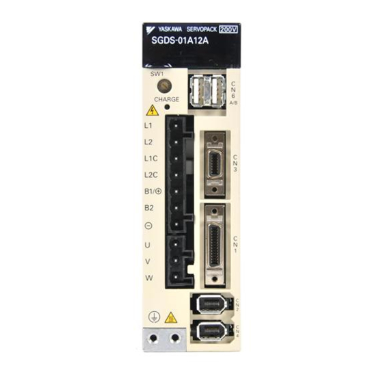
Refer to 2.2 SERVOPACK Model Indicates that data is being transmitted between Designations. the SERVOPACK and the MECHATROLINK-II YASKAWA SERVOPACK 2 0 0 V system. Rotary switch (SW1) S G D S - 0 2 A 1 2 A Refer to 10.1.1 Status Display on Panel Operator. -
Page 27: Examples Of Servo System Configurations
1 Outline 1.4 Examples of Servo System Configurations This section describes examples of basic servo system configuration. (1) Connecting to SGMAH and SGMPH Servomotors... - Page 28 1.4 Examples of Servo System Configurations Connect the main circuit cable and encoder cable to SGMAH or SGMPH servomotor in the following manner. Do not directly touch the connector pins provided with the servomotor. Particularly, the encoder may be IMPORTANT damaged by static electricity, etc.
- Page 29 1 Outline (2) Connecting to SGMSH, SGMGH Servomotors Power Supply Three-phase 200VAC SGMGH Servomotor...
- Page 30 1.4 Examples of Servo System Configurations (3) Connecting to SGMCS Servomotor Power supply Single-phase 100 or 200 VAC Molded-case circuit breaker Note: Refer to 4.4.10 AC/DC Reactor for Harmonic (MCCB) Suppression for the connection of AC/DC Protects the power supply reactor Suppression.
-
Page 31: Applicable Standards
1 Outline 1.5.1 North American Safety Standards (UL, CSA) 1.5 Applicable Standards 1.5.1 North American Safety Standards (UL, CSA) LISTED ∗1 ∗2 Model Certifications Standards (UL File No.) Standards CSA C22.2 • SGDS- A12A UL508C (E147823) SERVOPACK No.14 • SGMAH •... - Page 32 System Selection 2.1 Servomotor Model Designations - - - - - - - - - - - - - - - - - - - - - 2-2 2.1.1 Model SGMAH/SGMPH/SGMSH - - - - - - - - - - - - - - - - - - - - - - - - - - 2-2 2.1.2 Model SGMCS - - - - - - - - - - - - - - - - - - - - - - - - - - - - - - - - - - - - - - - 2-4 2.2 SERVOPACK Model Designations - - - - - - - - - - - - - - - - - - - 2-5 2.3 Σ...
-
Page 33: System Selection
2 System Selection 2.1.1 Model SGMAH/SGMPH/SGMSH 2.1 Servomotor Model Designations This section explains how to check the servomotor model and ratings. The alphanumeric codes after SGM S indicate the specifications. 2.1.1 Model SGMAH/SGMPH/SGMSH (1) Without Gears SGMAH - 01 A A F 4 1 Accessories Standard Sigma II Servomotor Type... - Page 34 2.1 Servomotor Model Designations SGMGH - 09 A C A 6 C Sigma Servomotor Type Accessories 1: Standard Rated Output C: 24V Brake 05: 500W (0.7hp) S: Shaft Seal 09: 850W (1.14hp) E: Brake and Shaft Seal 13: 1.3kW (1.7hp) 20: 2.0kW (2.7hp) Shaft Specifications 30: 3.0kW (4.0hp)
-
Page 35: Model Sgmcs
2 System Selection 2.1.2 Model SGMCS 2.1.2 Model SGMCS SGMCS 02 B 3 A 1 1 Σ–II Series SGMCS servomotor Σ-III Series servomotor SGMCS Rated Torque (N m) Motor Outer Diameter (mm) B φ135 C φ175 D φ230 E φ290 Options Code Specifications... -
Page 36: Servopack Model Designations
2.2 SERVOPACK Model Designations 2.2 SERVOPACK Model Designations Select the SERVOPACK according to the applied servomotor. SGDS - A 01 A R Mounting Method Σ-III Series SGDS Code Mounting Method SERVOPACK Base-mounted − as standard Rack-mounted Rated Output of Rated Output of Design Revision Order Applicable Servomotor Applicable Servomotor... -
Page 37: Σ Iii Series Servopacks And Applicable Servomotors
2 System Selection 2.3 Σ III Series SERVOPACKs and Applicable Servomotors Table 2.1 SERVOPACKs and Applicable Servomotors Σ III Series SGDS SERVOPACK Servomotor Type Single-phase Single-phase Three-phase 100 VAC 200 VAC 200 VAC − SGMAH A5A (50 W) (Super High Power −... -
Page 38: Selecting Cables
2.4 Selecting Cables 2.4 Selecting Cables 2.4.1 Cables for SGMAH and SGMPH Servomotors • Standard Connection SGMAH and SGMPH–01 to –04 Servomotor for 100W to 400W • Encoder cable extension from 20 m (65.6 ft) up to 50 m (164 ft) SGMAH and 100W to 400W SGMPH–01 to –04... - Page 39 2 System Selection 2.4.1 Cables for SGMAH and SGMPH Servomotors • Use the table below to select pre-wired cables for your SGMAH Sigma II series servomotor. Motor Item Cable Description (C) Size Part Number* Comments Class (kW) Power Cable JZSP-CMM00- without Brake These cables are available in five lengths.
- Page 40 2.4 Selecting Cables • Use the table below to select mating connectors or kits for your SGMAH Sigma II series servomotor. Motor Size Item Connector Description (D) Part Number Comments (kW) Class Motor Power Mating Connector JZSP-CMM9-1 (without Brake) These connector kits include pin and socket.
- Page 41 2 System Selection 2.4.1 Cables for SGMAH and SGMPH Servomotors • Use the table below to select pre-wired cables for your SGMPH Sigma II servomotor. Motor Size Item Cable Description (C) Part Number* Comments (kW) Class 0.1, 0.2, B4ICE- 0.4, 0.8 Power Cable with Interconnectron Connectors These UL and CE...
- Page 42 2.4 Selecting Cables • Use the table below to select mating connectors or kits for your SGMPH Sigma II series servomotor. Motor Size Item Connector Description (D) Part Number Comments (kW) Class Interconnectron Connector for Motor Power Cable (with or FIN07S-B2 Solder Cup without Brake)
-
Page 43: Cables For Sgmsh Servomotor
2 System Selection 2.4.2 Cables for SGMSH Servomotor 2.4.2 Cables for SGMSH Servomotor • Standard Connection SGDS SERVOPACK Battery case (Required when an absolute encoder is used.) Encoder cable Servomotor main circuit cable SGMSS Servomotor SGMSH Servomotor 2-12... - Page 44 2.4 Selecting Cables • Use the table below to select pre-wired cables for your SGMSH Sigma II series servomotor. Part Number* Motor Item Cable Description (C) Size Comments Class without (kW) with Brake Brake 1.0, Use the following key to 1.5, B1E- B1BE-...
- Page 45 2 System Selection 2.4.2 Cables for SGMSH Servomotor • Use the table below to select mating connectors for your SGMSH Sigma II series servomotor. Motor Part Number Item Connector Description (D) Size Comments Class without Brake with Brake (kW) MS3106B18-10S MS3106B20-15S Straight-type connector 1.0,...
- Page 46 2.4 Selecting Cables • Use the table below to select shielded pre-wired cables for your SGMSH Sigma II servomotor. These are suitable for IP67 environments. Part Number* Motor Item Cable Description (C) Size Comments Class (kW) without Brake with Brake 1.0, B1CE- Use the following key to...
-
Page 47: Cables For Sgmgh Servomotors
2 System Selection 2.4.3 Cables for SGMGH Servomotors 2.4.3 Cables for SGMGH Servomotors • Standard Connection SGDS SERVOPACK Battery case (Required when an absolute encoder is used.) Encoder cable Servomotor main circuit cable SGMGH SGMSS Servomotor Servomotor 2-16... - Page 48 2.4 Selecting Cables • Use the table below to select pre-wired cables for your SGMGH Sigma II series servomotor Motor Part Number* Item Cable Description (C) Size Comments Class without Brake with Brake (kW) 0.5, Use the following key to 0.9, B1E- B1BE-...
- Page 49 2 System Selection 2.4.3 Cables for SGMGH Servomotors • Use the table below to select mating connectors for each SGMGH Sigma II series servomotor. Part Number Motor Size Item Connector Description (D) Comments (kW) Class without Brake with Brake MS3106B18-10S MS3106B20-15S Straight-type connector 0.5, 0.9,...
- Page 50 2.4 Selecting Cables • Use the table below to select shielded pre-wired power cables for your SGMGH Sigma II series servomotor. Part Number* Motor Item Cable Description (C) Comments Size (kW) Class without Brake with Brake B1CE- B1BCE- 0.5, 0.9, 1.3 Use the following key to specify needed B2CE-...
-
Page 51: Cables For Sgmcs Servomotor
2 System Selection 2.4.4 Cables for SGMCS Servomotor 2.4.4 Cables for SGMCS Servomotor • Standard Connection SGDS SERVOPACK Servomotor Encoder SGMCS cable main circuit cable Servomotor View A Servomotor Encoder cable main circuit cable • Encoder cable extension from 20 m (65.6 ft) up to 50 m (164 ft) SGDS SERVOPACK Relay encoder cable extension. - Page 52 2.4 Selecting Cables Type Servomotor Flexible Name Length Specifications Standard Model ∗1 Type Type JZSP-CMP60-03 JZSP-CSP60-03 (9.84 ft) JZSP-CMP60-05 JZSP-CSP60-05 (16.4 ft) Cable with connectors at SERVOPACK end Encoder end both ends 10 m JZSP-CMP60-10 JZSP-CSP60-10 (For incremental and (32.8 ft) absolute encoder) 15 m JZSP-CMP60-15 JZSP-CSP60-15...
- Page 53 2 System Selection 2.4.4 Cables for SGMCS Servomotor Type Servomotor Name Length Flexible Specifications Standard Model ∗1 Type Type Servomo tor Main Soldered Circuit ∗2 Servomotor end connector JN1DS04FK1 Cable Connectors (Cont.) Encoder end SERVOPACK end Encoder end 0.3 m Encoder (Same for incremental and JZSP-CSP13...
-
Page 54: Selecting Peripheral Devices
2.5 Selecting Peripheral Devices 2.5 Selecting Peripheral Devices 2.5.1 Special Options With front cover open MECHATROLINK/ MECHATROLINK-II Connection cable Analog monitor cable Connect to the DF0300413 PC MECHATROLINK/ MECHATROLINK-II S/N D0024B958810004 Digital operator Connection cable POWER for digital operator I/O signal cable LED indicator or External device Battery for absolute encoder... - Page 55 2 System Selection 2.5.1 Special Options Refer- Name Length Type Figure ence Soldered SERVOPACK and Encoder Cable for − JZSP-CMP9-1 connector kit Fully-closed Control JZSP-CLP20-03 (9.84 ft) JZSP-CLP20-05 (16.4 ft) SERVOPACK Serial converter unit end 10 m Connection Cable for Serial 4.4.12 JZSP-CLP20-10 (32.8 ft)
-
Page 56: Molded-Case Circuit Breaker And Fuse Capacity
2.5 Selecting Peripheral Devices 2.5.2 Molded-case Circuit Breaker and Fuse Capacity Servo Amp. Model Current Capacity of Power Supply Capacity Main Circuit Molded-case Circuit Breaker or Fuse per Servo Amplifier Capacity Power Supply SGDS- (kVA) *1,*2 (kW) (Refer to 4.4.5) 0.05 0.25 0.10... -
Page 57: Noise Filters, Magnetic Contactors, Surge Protectors And Ac/Dc Reactors
2. The following table shows the manufacturers of each device. Peripheral Device Manufacturer Noise Filter Schaffner Electronic Magnetic Contactor Yaskawa Siemens Automation & Drives Corp. Surge Protector Okaya Electric Industries Co., Ltd. AC/DC Reactor Yaskawa Controls Co., Ltd. 2-26... -
Page 58: Regenerative Resistors
2.5 Selecting Peripheral Devices 2.5.4 Regenerative Resistors SERVOPACK Model Regenerative Resistor (Refer to 4.4.3 and 5.7) Main Circuit Built-in Power Supply Capacity SGDS- Externally Connected Resistance Capacity (kW) (Ω) 0.05 0.10 Single-phase − − − 100 V 0.20 0.40 0.05 0.10 −... - Page 59 2 System Selection 2.5.4 Regenerative Resistors 2-28...
- Page 60 SERVOPACK Specifications and Dimensional Drawings 3.1 SERVOPACK Ratings and Specifications - - - - - - - - - - - - - - 3-2 3.2 SERVOPACK Installation - - - - - - - - - - - - - - - - - - - - - - - - - - 3-5 3.3 SERVOPACK Internal Block Diagrams - - - - - - - - - - - - - - - - 3-7 3.3.1 Single-phase 100 V, 50 W to 400 W - - - - - - - - - - - - - - - - - - - - - - - - 3-7 3.3.2 Single-phase 200 V, 50 W to 400 W - - - - - - - - - - - - - - - - - - - - - - - - 3-8...
-
Page 61: Servopack Specifications And Dimensional Drawings
3 SERVOPACK Specifications and Dimensional Drawings 3.1 SERVOPACK Ratings and Specifications SERVOPACK Model SGDS- Max. Applicable Servomotor Capacity 0.05 0.75 [kW] 100 V Continuous Output Current − − − − − 0.66 0.91 [Arms] − − − − − Max. Output Current [Arms] 200 V Continuous Output Current 0.66... - Page 62 3.1 SERVOPACK Ratings and Specifications SERVOPACK Model SGDS- Dynamic Brake (DB) Operated at main power OFF, servo alarm, servo OFF or overtravel Regenerative Processing External regenerative resistor Built-in Overtravel Prevention (OT) Dynamic brake stop at P-OT or N-OT input, deceleration to a stop, or free run to a stop ≤...
- Page 63 3 SERVOPACK Specifications and Dimensional Drawings Applicable SERVOPACK Model SGDS- All Capacities MECHATROLINK Communications MECHATROLINK II MECHATROLINK Communications Protocol Station Address 41H to 5FH 41H to 4FH (Max. number of slaves : 30) (Max. number of slaves : 15) Transmission Speed 10 Mbps 4 Mbps Transmission Cycle...
-
Page 64: Servopack Installation
3.2 SERVOPACK Installation 3.2 SERVOPACK Installation The SGDS SERVOPACK can be mounted on a base or on a rack. Incorrect installation will cause problems. Always observe the following installation instructions. WARNING • After voltage resistance test, wait at least five minutes before servicing the product. (Refer to “Voltage Resistance Test”... - Page 65 Follow the procedure below to install multiple SERVOPACKs side by side in a control panel. Cooling fan Cooling fan 50 mm (1.97in) min. YASKAWA SERVOPACK 2 0 0 V YASKAWA SERVOPACK 2 0 0 V YASKAWA SERVOPACK 2 0 0 V YASKAWA SERVOPACK 2 0 0 V...
-
Page 66: Servopack Internal Block Diagrams
3.3 SERVOPACK Internal Block Diagrams 3.3 SERVOPACK Internal Block Diagrams 3.3.1 Single-phase 100 V, 50 W to 400 W Single-phase 100 to 115 V Single-phase 100 V, 50 W to 400 W Model SGDS F12A ( =A5 to 04) 50/60Hz Noise filter Servomotor... -
Page 67: Single-Phase 200 V, 50 W To 400 W
3 SERVOPACK Specifications and Dimensional Drawings 3.3.2 Single-phase 200 V, 50 W to 400 W 3.3.2 Single-phase 200 V, 50 W to 400 W Single-phase 200 to 230 V Single-phase 200 V, 50W to 400W and 800 W Model 800W SGDS A12A ( =A5 to 04,08) (50/60 HZ) -
Page 68: Three-Phase 200
3.3 SERVOPACK Internal Block Diagrams 3.3.3 Three-phase 200 V, 1.0 kW... -
Page 69: Single-Phase 200 V 800 W
3 SERVOPACK Specifications and Dimensional Drawings 3.3.4 Single-phase 200 V 800 W 3.3.4 Single-phase 200 V 800 W Single-phase +10% 200 to 230 V -15% Single-phase 200 V, 800 W Model SGDS 08A12A (50/60 Hz) Noise Servomotor filter Varistor Dinamic brake circuit Temperature Current... -
Page 70: Three-Phase 200 V, 3.0~5.0Kw
3.3 SERVOPACK Internal Block Diagrams 3.3.5 Three-phase 200 V, 3.0~5.0kW Three-phase +10% 200 to 250V -15% B2 B3 (50\60Hz) FAN1 AC servomotor Noise filter ±12V CHARGE Gate drive over- Voltage current protection Relay drive Gate drive sensor Voltage sensor Gate drive Interface Current sensor... -
Page 71: Servopack Power Supply Capacities And Power Losses
3 SERVOPACK Specifications and Dimensional Drawings 3.3.5 Three-phase 200 V, 3.0~5.0kW 3.4 SERVOPACK Power Supply Capacities and Power Losses The following table shows SERVOPACK power supply capacities and power losses at the rated output. Table 3.1 SERVOPACK Power Losses at Rated Output Maximum Output Main Cir-... -
Page 72: Servopack Overload Characteristics And Load Moment Of
3.5 SERVOPACK Overload Characteristics and Load Moment of Inertia 3.5 SERVOPACK Overload Characteristics and Load Moment of Inertia 3.5.1 Overload Characteristics The overload detection level is set under hot start conditions at a servomotor ambient temperature of 40°C (104°F). 10000 1000 Operating time (s) Rated torque... -
Page 73: Load Moment Of Inertia
• Reduce the deceleration rate. • Reduce the maximum motor speed. • Install an externally mounted regenerative resistor if the alarm cannot be cleared. Contact your Yaskawa Application Engineering Department. Regenerative resistors are not built into 200 V SERVOPACKs for 50 W to 400 W or 100 V SERVOPACKs for 50 W to 400 W. - Page 74 3.5 SERVOPACK Overload Characteristics and Load Moment of Inertia (1) Load Moment of Inertia and Motor Speed for SGMAH Servomotors (a) 200V SGMAH - O1 SGMAH - A5 SGMAH - A3 5000 5000 5000 4000 4000 4000 3000 3000 3000 2000 2000 2000...
- Page 75 3 SERVOPACK Specifications and Dimensional Drawings 3.5.3 Load Moment of Inertia (2) Load Moment of Inertia and Motor Speed for SGMPH Servomotors (a) 200V SGMPH - 01 SGMPH - 02 SGMPH - 04 5000 5000 5000 4000 4000 4000 3000 3000 3000 2000...
- Page 76 3.5 SERVOPACK Overload Characteristics and Load Moment of Inertia (4) Load Moment of Inertia and Motor Speed for SGMSH Servomotors (a) 200V SGMSH-10A SGMSH-15A 5000 5000 4000 4000 3000 3000 2000 2000 1000 1000 TORQUE (N キ m) TORQUE (N キ m) TORQUE (lb キ...
- Page 77 3 SERVOPACK Specifications and Dimensional Drawings 3.5.3 Load Moment of Inertia (5) Load Moment of Inertia and Motor Speed for SGMCS Servomotors SGMCS-02B(42W) SGMCS-05B(105W) SGMCS-07B(147W) Load Load Load moment moment moment of inertia 183.5 of inertia (×10 kg m of inertia (×10 kg m (×10...
- Page 78 3.5 SERVOPACK Overload Characteristics and Load Moment of Inertia (6) Allowable Load Moment of Inertia at the Motor Shaft The rotor moment of inertia ratio is the value for a servomotor without a gear and a brake. Servomotor Capacity Range Allowable Load Moment of Inertia Model (Rotor Moment of Inertia Ratio)
-
Page 79: Servopack Dimensional Drawings
3 SERVOPACK Specifications and Dimensional Drawings 3.5.3 Load Moment of Inertia 3.6 SERVOPACK Dimensional Drawings SERVOPACK dimensional drawings are grouped according to the mounting method and capacity. (1) Base-mounted Type Supply Voltage Capacity Reference Section 3.7.1 50 W / 100 W / 200 W 100 V 3.7.2 400 W... -
Page 80: Dimensional Drawings Of Base-Mounted Servopack Model Sgds- 12A / - 12A
3.7 Dimensional Drawings of Base-mounted SERVOPACK Model SGDS- 12A / - 3.7.1 Single-phase 100 V/200 V, 50 W/100 W/200 W Approx.mass: 0.7 kg Unit: mm Mounting Hole Diagram 2 × M4 screw holes (4.5) YASKAWA SERVOPACK 200V SGDS- CHARGE B1/ + Terminal block − YASKAWA ELECTRIC MADE IN JAPAN 32±0.5... -
Page 81: Single-Phase 200 V, 400 W
3 SERVOPACK Specifications and Dimensional Drawings 3.7.3 Single-phase 200 V, 400 W 3.7.3 Single-phase 200 V, 400 W Approx.mass: 0.9 kg Unit: mm Mounting Hole Diagram 2 × M4 screw holes 200V YASKAWA SERVOPACK SGDS- CHARGE B1/ + Terminal block − YASKAWA ELECTRIC... - Page 82 3.7 Dimensional Drawings of Base-mounted SERVOPACK Model SGDS- 12A / - Three-phase, 1.5kW 3-23...
- Page 83 3 SERVOPACK Specifications and Dimensional Drawings 3.7.4 Single-phase 200 V, 800 W, Three-phase 200 V, 1.0 kW Three-phase, 2.0kW, 3.0kW 3-24...
-
Page 84: Specifications And Dimensional Drawings Of Cables And Peripheral Devices
Specifications and Dimensional Drawings of Cables and Peripheral Devices 4.1 SERVOPACK Main Circuit Wire Size - - - - - - - - - - - - - - - - - 4-2 4.2 Connectors for Main Circuit, Control Power Supply, and Servomotor Cable - - - - - - - - - - - - - - - - - - - - - - - - - - - - - - - 4-4 4.2.1 Spring Type (Standard) - - - - - - - - - - - - - - - - - - - - - - - - - - - - - - - - - - 4-4 4.2.2 Crimp Type (Option) - - - - - - - - - - - - - - - - - - - - - - - - - - - - - - - - - - - - 4-5... -
Page 85: Servopack Main Circuit Wire Size
4 Specifications and Dimensional Drawings of Cables and Peripheral Devices 4.1 SERVOPACK Main Circuit Wire Size (1) Cable Types Cable Types Allowable Conductor Symbol Temperature Name °C Normal vinyl cable 600-V vinyl cable Temperature-resistant vinyl cable The table shows the wire size and allowable currency for three cables. Use a cable whose specifications meet or are less than the values in the table. - Page 86 4.1 SERVOPACK Main Circuit Wire Size (4) Three-phase for 200 V SERVOPACK Model Terminal SGDS- External Terminal Name Symbol 10AE 1.5AE 2.0AE 3.0AE HIV2.0 Main circuit power input terminals L1, L2, L3 HIV2.0 Servomotor connection terminals U, V, W HIV1.25 Control power input terminals L1C, L2C HIV2.0...
-
Page 87: Connectors For Main Circuit, Control Power Supply, And Servomotor Cable
4 Specifications and Dimensional Drawings of Cables and Peripheral Devices 4.2.1 Spring Type (Standard) 4.2 Connectors for Main Circuit, Control Power Supply, and Servomo- tor Cable 4.2.1 Spring Type (Standard) Spring-type connectors are provided on SERVOPACK as standard. (1) Connector Types Appearance Type Manufacturer... -
Page 88: Crimp Type (Option)
4.2 Connectors for Main Circuit, Control Power Supply, and Servomotor Cable 4.2.2 Crimp Type (Option) The crimp type connectors are options. Contact the manufacturer for details. (1) Connector Types Appearance Types Manufacturer 3-pole (For servomotor main circuit cable connector at 51241-0311 SERVOPACK end) 51241-0711... - Page 89 4 Specifications and Dimensional Drawings of Cables and Peripheral Devices 4.2.2 Crimp Type (Option) (3) Plugs (Chained/Detached) Trademark 25.9 (1.02) 6.3 (0.25) 17.1 (0.67) 3.1 (0.12) 1.8 (0.07) ∗ 4 (0.16) 0.3 (0.01) min. Cut-off type ∗ Reference length Units: mm (in)
-
Page 90: Cn1 Cables For I/O Signals
4.3 CN1 Cables for I/O Signals 4.3 CN1 Cables for I/O Signals 4.3.1 Connector Type and Cable Size Use the following connector and wire for CN1. The connector CN1 includes a set of case and a connector. Case Connector Connector Type Type Type 10126-3000VE*... -
Page 91: Peripheral Devices
4.4.1 Digital Operator 4.4 Peripheral Devices 4.4.1 Digital Operator (1) Model JUSP-OP05A with a 1m-connection Cable SERVOPACK YASKAWA SERVOPACK 2 0 0 V S G D S - 0 2 A 1 2 A CHARGE A / B Connect Digital Operator... -
Page 92: External Regenerative Resistor
4.4 Peripheral Devices (2) Dimensional Drawings ∗ Socket: DF11-4DS-2C Black ∗ Connector: DF11-2428SCF Black +0.79 1000 mm (39.37 White ∗ Hirose Electric Corporation. Viewed from the cable (3) Specifications Pin Number Cable Color Signal Name Factory Setting Analog Monitor 2 Motor speed: 1 V / 1000 RPM Torque reference: 1 V / 100% rated White... - Page 93 4 Specifications and Dimensional Drawings of Cables and Peripheral Devices 4.4.3 External Regenerative Resistor (3) Specifications K: ± 10%, J: ± 5%, H: ± 3% Resistance Tolerance Temperature Resistance ± 400 PPM / °C (20Ω max.) , ± 260 PPM / °C (20Ω min.) Characteristics ∆...
-
Page 94: Absolute Encoder Battery
4.4 Peripheral Devices 4.4.4 Absolute Encoder Battery A backup battery is required to maintain the position of absolute encoder. Install one of the absolute encoder batteries below. (1) Battery Model: JZSP-BA01 (lithium battery) (Battery: ER3V battery made by Toshiba Battery Co., Ltd.) 3.6 V 1000 mAh Connector Battery ER3V... -
Page 95: Molded-Case Circuit Braker (Mccb)
4 Specifications and Dimensional Drawings of Cables and Peripheral Devices 4.4.5 Molded-case Circuit braker (MCCB) (3) Specification Location Specification Model Number Manufacturer Lithium battery Encoder cable ER3V Toshiba Battery Co., Ltd. 3.6 V, 1000 mAh Lithium battery Host controller ER6VC3 Toshiba Battery Co., Ltd. -
Page 96: Noise Filter
4.4 Peripheral Devices 4.4.6 Noise Filter The recommended noise filter is manufactured by Schaffner EMC Inc., 52 Mayfield Ave., Edison, SCHAFFNER NJ 08837, 1-800-367-5566, http://www.shaffner.com. Select one of the following noise filters according to SERVOPACK capacity. For more details on selecting current capacity for a noise filter, refer to 2.5.3 Noise Filters, Magnetic Contactors, Surge Protectors and AC/DC Reactors. - Page 97 4 Specifications and Dimensional Drawings of Cables and Peripheral Devices 4.4.6 Noise Filter (1) Single-phase, 100/200 V Model FN2070-6/07 FN2070-10/07 FN2070-16/07 Side view Side view Top view Top view Dimensional Drawings Contact Terminal P/N/E Tolerance Dimensions 113.5±1 156±1 119±0.5 (4.69±0.020) (4.47±0.039) (6.14±0.039) ±1 (±0.039)
- Page 98 4.4 Peripheral Devices (2) Three-phase, 200 V Select one of the following noise filters according to SERVOPACK capacity. For more details on selecting current capacity for a noise filter, refer to 2.5.3 Noise Filters, Magnetic Contactors, Surge Protectors and AC/DC Reactors.
-
Page 99: Magnetic Contactor
4.4.7 Magnetic Contactor HI- J (1) Model: The magnetic contactor is manufactured by Yaskawa Controls Co., Ltd. Contact your Yaskawa representative for details. A magnetic contactor is required to make the AC power to SERVOPACK ON/OFF sequence externally. Be sure to attach a surge protector to the excitation coil of the magnetic contactor. -
Page 100: Surge Protector
4.4 Peripheral Devices 4.4.8 Surge Protector R C M-601BQZ-4 and R C M-601BUZ-4 (1) Model: Manufactured by Okaya Electric Industries Co., Ltd. The surge protector absorbs surge voltage generated when the magnetic coil is OFF. This prevents faulty operation in or damage to electronic circuits near the magnetic contactors or switches. Recommended surge protectors are listed below. -
Page 101: Ac/Dc Reactors For Power Supplied Designed For Minimum Harmonics
4.4.9 AC/DC Reactors for Power Supplied Designed for Minimum Harmonics (1) Specifications Manufactured by Yaskawa Controls Co., Ltd. Contact your Yaskawa representative for details. If necessary for power supplied designed for minimum harmonics, connect an AC reactor to the AC line for the... -
Page 102: Mechatrolink/Mechatrolink Ii Communication Cable
4.4 Peripheral Devices 4.4.10 MECHATROLINK/MECHATROLINK II Communication Cable (1) Model: JEPMC-W6003- Type Cable Model Cable length (L) JEPMC-W6003-A5 0.5 m MECHATROLINK Communication Cable JEPMC-W6003-01 1.0 m (with connectors at both ends) JEPMC-W6003- is the ordered length [m] (2) Dimensional Drawings (3) Wiring Specifications Pin No. -
Page 103: Cable With Connectors At Both Ends For Fully-Closed Control
4 Specifications and Dimensional Drawings of Cables and Peripheral Devices 4.4.12 Cable with Connectors at both ends for Fully-closed Control 4.4.12 Cable with Connectors at both ends for Fully-closed Control Use to connect the SERVOPACK and Serial converter unit. (1) Model: JZSP-CLP20-03: (3 m) JZSP-CLP20-05: (5 m) JZSP-CLP20-10: (10 m) JZSP-CLP20-15: (15 m) - Page 104 4.4 Peripheral Devices 2-#4-40 UNC tap Nameplate 4 - φ 4.2 hole 2 - φ 4.2 hole 4-M5 tap, depth 10 2-#4-40 UNC tap (b) JZDP-A005-000 (for the encoder by Renishaw Inc.) Nameplate 4 - φ 4.2 hole 4-M5 tap, depth 10 2 - φ...
- Page 105 4 Specifications and Dimensional Drawings of Cables and Peripheral Devices 4.4.13 Serial Converter Unit for Fully-closed Control 4-22...
- Page 106 Wiring 5.1 Wiring Main Circuit - - - - - - - - - - - - - - - - - - - - - - - - - - - - - - 5-2 5.1.1 Names and Descriptions of Main Circuit Terminals - - - - - - - - - - - - - - 5-2 5.1.2 Wiring Main Circuit Terminal Block (Spring Type) - - - - - - - - - - - - - - - 5-3 5.1.3 Typical Main Circuit Wiring Examples - - - - - - - - - - - - - - - - - - - - - - - 5-4 5.2 Wiring Encoders - - - - - - - - - - - - - - - - - - - - - - - - - - - - - - - - 5-7...
-
Page 107: Wiring
5 Wiring 5.1.1 Names and Descriptions of Main Circuit Terminals 5.1 Wiring Main Circuit This section describes typical examples of main circuit wiring, functions of main circuit terminals, and the power ON sequence. CAUTION • Do not bundle or run power and signal lines together in the same duct. Keep power and signal lines separated by at least 30 cm (11.81 inches). -
Page 108: Wiring Main Circuit Terminal Block (Spring Type)
5.1 Wiring Main Circuit 5.1.2 Wiring Main Circuit Terminal Block (Spring Type) CAUTION • Observe the following precautions when wiring main circuit terminal block. • Remove the terminal block from the SERVOPACK prior to wiring. • Insert only one wire per terminal on the terminal block. •... -
Page 109: Typical Main Circuit Wiring Examples
5 Wiring 5.1.3 Typical Main Circuit Wiring Examples 5.1.3 Typical Main Circuit Wiring Examples (1) Single-phase, 100/200 V SERVOPACK SGDS- (For servo +24V alarm display) ALM+ 31 Main power Main supply power supply ALM- 1PRT : Relay Molded-case circuit breaker : Indicator lamp : Noise filter : Surge protector... - Page 110 5.1 Wiring Main Circuit Designing a Power ON Sequence IMPORTANT Note the following points when designing the power ON sequence. • Design the power ON sequence so that main power is turned OFF when a servo alarm signal is output. (See the circuit figure above.) •...
- Page 111 5 Wiring 5.1.3 Typical Main Circuit Wiring Examples (4) DC Power Supply Input WARNING • Do not use a DC power supply for 100V SERVOPACK SGDS- A DC power supply will destroy the SERVOPACK, which may cause a fatal accident or fire. Do not change the factory setting for Pn001, which is preset to ZERO (n.
-
Page 112: Wiring Encoders
5.2 Wiring Encoders 5.2 Wiring Encoders The connection cables between encoder and SERVOPACK and wiring pin numbers differ depending on servomotor model. Refer to 4 Specifications and Dimensional Drawings of Cables and Peripheral Devices for details. 5.2.1 Connecting an Encoder (1) Incremental Encoders (2) Absolute Encoders... -
Page 113: Cn2 Encoder Connector Terminal Layout
5 Wiring 5.2.2 CN2 Encoder Connector Terminal Layout 5.2.2 CN2 Encoder Connector Terminal Layout PG5V PG power supply PG 0 V PG power supply +5 V BAT (+) Battery (+) BAT (-) Battery (-) (For an absolute encoder) (For an absolute encoder) PG serial signal input PG serial signal input −... -
Page 114: I/O Signal Connections
5.3 I/O Signal Connections 5.3 I/O Signal Connections 5.3.1 Connection Example of I/O Signal The following diagram shows a typical example of I/O signal connections. Photocoupler output Max. operating voltage : 30 VDC SGDS SERVOPACK Max. output current : 50mA DC Control power supply 3.3kΩ... -
Page 115: I/O Signal Connector (Cn1) Terminal Layout
5 Wiring 5.3.2 I/O Signal Connector (CN1) Terminal Layout 5.3.2 I/O Signal Connector (CN1) Terminal Layout The following diagram shows the layout of the CN1 terminals. Brake interlock /BK+ Battery (+) ∗2 BAT(+) (/SO1+) output input /BK- Battery (-) Brake interlock ∗2 BAT(-) (/SO1-) -
Page 116: Interface Circuit
5.3 I/O Signal Connections (2) Output Signals Signal Name Pin No. Function Com- ALM+ Servo alarm signal: ALM- Turns OFF when an error is detected. /BK+ (/SO1+) Brake interlock signal: /BK- (/SO1-) Controls the brake. The brake is released when the signal is ON. /SO2+ General-purpose output signal: /SO2-... - Page 117 5 Wiring 5.3.4 Interface Circuit (b) Photocoupler Output Circuit Photocoupler output circuits are used for servo alarm (ALM), brake interlock (/BK), and other sequence output signal circuits. Connect a photocoupler output circuit through a relay or line receiver circuit. Relay Circuit Example Line Receiver Circuit Example SERVOPACK SERVOPACK...
-
Page 118: Wiring Mechatrolink Ii Communications
5.4 Wiring MECHATROLINK II Communications 5.4 Wiring MECHATROLINK II Communications The following diagram shows an example of connections between a host controller and a SERVOPACK using MECHATROLINK II communications cables (CN6A, CN6B). 5.4.1 Wiring Example MECHATROLINK II Communications CN6A Pulse transformer MECHATROLINK-II 120 Ω... -
Page 119: Mechatrolink Ii Communications Connectors (Cn6A, Cn6B)
5 Wiring 5.4.2 MECHATROLINK II Communications Connectors (CN6A, CN6B) 5.4.2 MECHATROLINK II Communications Connectors (CN6A, CN6B) The terminal layout and specifications of the CN6A and CN6B connectors are shown below. (1) CN6A and CN6B Connectors Terminal Layout − Not connected Serial data I/O Not connected Note: The connector shell is connected to the FG (frame ground). - Page 120 Cable, 4.4.11 MECHATROLINK/MECHATROLINK II Terminator. A MECHATROLINK II wiring diagram is shown below. Host controller YASKAWA SERVOPACK 2 0 0 V YASKAWA SERVOPACK 2 0 0 V YASKAWA SERVOPACK 2 0 0 V S G D S - 0 2 A 1 2 A...
-
Page 121: Fully-Closed Encoder Connections
JZDP-A003-000 Linear encoder SGDS- by Heidenhain Corp. JZSP-CLP20- Connection cable by Heidenhain Corp. Note: Contact Yaskawa Electric Corporation for the devices drawn in bold lines. (3) Pin Assignments Signal Signal Pin No. Pin No. cos input (A+) Linear encoder end... -
Page 122: Connection Example Of Linear Scale By Renishaw
Serial converter unit JZDP-A005-000 Linear encoder SGDS- by Renishaw Inc. JZSP-CLP20- D-sub 15-pin connector Note: Contact Yaskawa Electric Corporation for the devices drawn in bold lines. (3) Pin Assignments Pin No. Signal Pin No. Signal /cos input (V1-) Linear encoder end... -
Page 123: Others
5 Wiring 5.6.1 Wiring Precautions 5.6 Others 5.6.1 Wiring Precautions To ensure safe and stable operation, always observe the following wiring precautions. 1. For wiring for reference inputs and encoders, use the specified cables. Refer to 4 Specifications and IMPORTANT Dimensional Drawings of Cables and Peripheral Devices for details. -
Page 124: Wiring For Noise Control
5.6 Others 5.6.2 Wiring for Noise Control (1) Wiring Example The SERVOPACK uses high-speed switching elements in the main circuit. It may receive “switching noise” from these high-speed switching elements if wiring or grounding around the SERVOPACK is not appropriate. To prevent this, always wire and ground the SERVOPACK correctly. -
Page 125: Wiring For Noise Control
5 Wiring 5.6.2 Wiring for Noise Control (3) Using Noise Filters Use an inhibit type noise filter to prevent noise from the power supply line. The following table lists recommended noise filters for each SERVOPACK model. Install a noise filter on the power supply line for peripheral equipment as necessary. Table 5.2 Noise Filters Main Circuit SERVOPACK Model... - Page 126 5.6 Others 2. Separate the noise filter ground wire from the output lines. Do not accommodate the noise filter ground wire, output lines and other signal lines in the same duct or bundle them together. Incorrect Correct Noise Noise Filter Filter The ground wire can be close to...
-
Page 127: Using More Than One Servopack
5 Wiring 5.6.3 Using More Than One SERVOPACK 5.6.3 Using More Than One SERVOPACK The following diagram is an example of the wiring when more than one SERVOPACK is used. Connect the alarm output (ALM) terminals for the three SERVOPACKs in series to enable alarm detection relay 1RY to operate. -
Page 128: Power Supply Voltage
* This is the net value at the rated load. Voltage conversion transfer SERVOPACK Single-phase YASKAWA SERVOPACK 2 0 0 V S G D S - 0 2 A 1 2 A 100 or 200 VAC CHARGE A / B... -
Page 129: Ac/Dc Reactor For Harmonic Suppression
5 Wiring 5.6.5 AC/DC Reactor for Harmonic Suppression 5.6.5 AC/DC Reactor for Harmonic Suppression (1) Reactor Types The SERVOPACK has reactor connection terminals for power supply harmonic suppression. The type of reactor to be connected differs depending on the SERVOPACK capacity. Refer to the following table. Reactor Specifications Applicable AC/DC Reactor... -
Page 130: Connecting Regenerative Resistors
5.7 Connecting Regenerative Resistors 5.7 Connecting Regenerative Resistors 5.7.1 Regenerative Power and Regenerative Resistance The rotational energy of driven machine such as servomotor is returned to the SERVOPACK. This is called regenerative power. The regenerative power is absorbed by charging the smoothing capacitor, but if the amount of power exceeds the capacity of the capacitor, the regenerative power is further consumed by the regenerative resistor. - Page 131 5 Wiring 5.7.2 Connecting Externally Regenerative Resistors (3) Precautions on Selecting External Regenerative Resistors • A built-in regenerative resistor is provided for 500 W to 1.0 kW SGDS SERVOPACKs as standard. When installing an external regenerative resistor in the SERVOPACK, make sure that the resistance is the same as that of the SERVOPACK’s built-in resistor.
- Page 132 Connect an external regenerative resistor between and B2 terminals. Note: The user must provide the regenerative resis- tor. YASKAWA SERVOPACK 2 0 0 V S G D S - 0 2 A 1 2 A CHARGE A / B (b) SERVOPACKs with Capacities Larger than 400W Enlarged View Disconnect the wiring between the SERVOPACK’s...
- Page 133 5 Wiring 5.7.2 Connecting Externally Regenerative Resistors 5-28...
-
Page 134: Mechatrolink Ii Communications
MECHATROLINK II Communications 6.1 Specifications and Configuration - - - - - - - - - - - - - - - - - - - - - 6-3 6.1.1 Specifications - - - - - - - - - - - - - - - - - - - - - - - - - - - - - - - - - - - - - - - - 6-3 6.1.2 System Configuration - - - - - - - - - - - - - - - - - - - - - - - - - - - - - - - - - - - 6-3 6.2 Switches for MECHATROLINK II Communications Settings - 6-4 6.2.1 Communications Settings - - - - - - - - - - - - - - - - - - - - - - - - - - - - - - - - 6-4... - Page 135 6 MECHATROLINK II Communications 6.3.27 Interpolation Feeding with Position Detection (LATCH: 38H) - - - - - - 6-33 6.3.28 External Input Positioning (EX_POSING: 39H) - - - - - - - - - - - - - - - 6-34 6.3.29 Homing (ZRET: 3AH) - - - - - - - - - - - - - - - - - - - - - - - - - - - - - - - - - 6-36 6.3.30 Velocity Control (VELCTRL: 3CH) - - - - - - - - - - - - - - - - - - - - - - - - 6-38 6.3.31 Torque Control (TRQCTRL: 3DH) - - - - - - - - - - - - - - - - - - - - - - - - - 6-39...
-
Page 136: Specifications And Configuration
6.1 Specifications and Configuration 6.1 Specifications and Configuration 6.1.1 Specifications Items that are not described in this chapter are based on the MECHATROLINK application layer. For more details, refer to the following manuals. • MECHATROLINK System User’s Manual (SIE-S800-26.1) • MECHATROLINK Servo Command User’s Manual (SIE-S800-26.2) 6.1.2 System Configuration The following illustration shows system configuration. -
Page 137: Switches For Mechatrolink Ii Communications Settings
6 MECHATROLINK II Communications 6.2.1 Communications Settings 6.2 Switches for MECHATROLINK II Communications Settings This section describes the switch settings necessary for MECHATROLINK II communications. 6.2.1 Communications Settings The SW2 DIP switch sets the MECHATROLINK II communications settings, as shown below. Settings that have been changed are enabled when the power is turned OFF and ON. -
Page 138: Setting The Station Address
6.2 Switches for MECHATROLINK II Communications Settings 6.2.3 Setting the Station Address The station address is set as shown in Table 4.2, using the rotary switch (SW1) and piano switch (SW2 bit 3). Settings that have been changed are enabled when the power is turned OFF and ON. The factory setting for the station address is 41H (SW2 bit 3 = OFF, SW1 = 1). -
Page 139: Main Commands
6 MECHATROLINK II Communications 6.3.1 No Operation (NOP: 00H) 6.3 Main Commands The following sections describe main command specific items that are unique to the SGDS- 12A. The MECHATROLINK II main commands are upwardly compatible with the MECHATROLINK commands. They use the first to the twenty nineteenth bytes of the command and response data. 03H is set in command byte 0, and 01H is returned to response byte 0. -
Page 140: Read Parameter (Prm_Rd: 01H)
6.3 Main Commands 6.3.2 Read Parameter (PRM_RD: 01H) Byte PRM_RD Description Command Response Processing Data communica- Synchronization Asynchronous classifications tions command classifications group ALARM Processing time Refer to the fol- Subcommand Cannot be used lowing table STATUS • Reads current operating parameters. The latest setting value, however, is read for offline parameters. -
Page 141: Write Parameter (Prm_Wr: 02H)
6 MECHATROLINK II Communications 6.3.3 Write Parameter (PRM_WR: 02H) 6.3.3 Write Parameter (PRM_WR: 02H) Byte PRM_WR Description Command Response Processing Data communica- Synchronization Asynchronous classifications tions command classifications group ALARM Processing time Refer to the fol- Subcommand Cannot be used lowing table STATUS •... -
Page 142: Read Id (Id_Rd: 03H)
6.3 Main Commands 6.3.4 Read ID (ID_RD: 03H) Byte ID_RD Description Command Response Processing Data communica- Synchronization Asynchronous classifications tions command classifications group ALARM Processing time Within communi- Subcommand Cannot be used cation cycle STATUS • Reads the ID. The corresponding DEVICE_COD is shown in the table on the following page. -
Page 143: Set Up Device (Config: 04H)
6 MECHATROLINK II Communications 6.3.5 Set Up Device (CONFIG: 04H) 6.3.5 Set Up Device (CONFIG: 04H) Byte CONFIG Description Command Response Processing Control com- Synchronization Asynchronous classifications mand group classifications ALARM Processing time ∗ Subcommand Cannot be used Within 4 s + α STATUS •... -
Page 144: Read Alarm Or Warning (Alm_Rd: 05H)
6.3 Main Commands 6.3.6 Read Alarm or Warning (ALM_RD: 05H) Byte ALM_RD Description Command Response Processing Control com- Synchronization Asynchronous classifications mand group classifications ALARM Processing time Refer to Subcommand Cannot be used • Details of ALM_RD_MOD STATUS • Reads the following alarm or warning status. - Current alarm/warning status - Alarm status history* (warning history is not preserved.) ALM_RD_... - Page 145 6 MECHATROLINK II Communications 6.3.6 Read Alarm or Warning (ALM_RD: 05H) Εach alarm code of the Σ III SERVOPACK is 2-byte long, which includes detailed information such as causes of occurrence in addition to the alarm code of Σ II series SERVOPACK. The data format of alarm code is as follows.
-
Page 146: Clear Alarm Or Warning (Alm_Clr: 06H)
6.3 Main Commands 6.3.7 Clear Alarm or Warning (ALM_CLR: 06H) Byte ALM_CLR Description Command Response Processing Control com- Synchronization Asynchronous classifications mand group classifications ALARM Processing time Refer to Subcommand Cannot be used • Details of ALM_CLR_MOD STATUS • Clears the following alarm or warning status. - Current alarm/warning status - Alarm status history * (warning history is not preserved.) ALM_CLR_... -
Page 147: Start Synchronous Communications (Sync_Set: 0Dh)
6 MECHATROLINK II Communications 6.3.8 Start Synchronous Communications (SYNC_SET: 0DH) 6.3.8 Start Synchronous Communications (SYNC_SET: 0DH) Byte SYNC_SET Description Command Response Processing Network com- Synchronization Asynchronous classifications mand group classifications ALARM Processing time Transmission Subcommand Cannot be used cycle or more STATUS •... -
Page 148: Mechatrolink Ii Connection (Connect: 0Eh)
6.3 Main Commands 6.3.9 MECHATROLINK II Connection (CONNECT: 0EH) Byte CONNECT Description Command Response Processing Network com- Synchronization Asynchronous classifications mand group classifications ALARM Processing time Communications Subcommand Cannot be used cycle or more STATUS • Establishes a MECHATROLINK II connection. Sets the communications mode according to COM_MOD. -
Page 149: Disconnection (Disconnect: 0Fh)
6 MECHATROLINK II Communications 6.3.10 Disconnection (DISCONNECT: 0FH) 6.3.10 Disconnection (DISCONNECT: 0FH) Byte DISCONNECT Description Command Response Processing Network com- Synchronization Asynchronous classifications mand group classifications ALARM Processing time Communications Subcommand Cannot be used cycle or more STATUS • Releases the MECHATROLINK II connection. The SERVOPACK changes communication to phase 1. -
Page 150: Read Non-Volatile Parameter (Pprm_Rd: 1Bh)
6.3 Main Commands 6.3.11 Read Non-volatile Parameter (PPRM_RD: 1BH) Byte PPRM_RD Description Command Response Processing Data communica- Synchronization Asynchronous classifications tions command classifications group ALARM Processing time Within communi- Subcommand Cannot be used cations cycle STATUS • This command is not supported. •... -
Page 151: Write Non-Volatile Parameter (Pprm_Wr: 1Ch)
6 MECHATROLINK II Communications 6.3.12 Write Non-volatile Parameter (PPRM_WR: 1CH) 6.3.12 Write Non-volatile Parameter (PPRM_WR: 1CH) Byte PPRM_WR Description Command Response Processing Data communica- Synchronization Asynchronous classifications tions command classifications group ALARM Processing time Within 200 ms Subcommand Cannot be used STATUS •... -
Page 152: Set Coordinates (Pos_Set: 20H)
6.3 Main Commands 6.3.13 Set Coordinates (POS_SET: 20H) Byte POS_SET Description Command Response Processing Data communica- Synchronization Asynchronous classifications tions command classifications group ALARM Processing time Within communi- Subcommand Cannot be used cation cycle STATUS • Sets coordinates. REFE can also enable home position (ZPOINT) and software limits. -
Page 153: Apply Brake (Brk_On: 21H)
6 MECHATROLINK II Communications 6.3.14 Apply Brake (BRK_ON: 21H) 6.3.14 Apply Brake (BRK_ON: 21H) Byte BRK_ON Description Command Response Processing Control com- Synchronization Asynchronous classifications mand group classifications ALARM Processing time Within communi- Subcommand Cannot be used. cations cycle STATUS •... -
Page 154: Release Brake (Brk_Off: 22H)
6.3 Main Commands 6.3.15 Release Brake (BRK_OFF: 22H) Byte BRK_OFF Description Command Response Processing Control com- Synchronization Asynchronous classifications mand group classifications ALARM Processing time Within communi- Subcommand Cannot be used cations cycle STATUS is set to 1. • Applies brake. This command is enabled when Pn50F.2 •... -
Page 155: Turn Sensor On (Sens_On: 23H)
6 MECHATROLINK II Communications 6.3.16 Turn Sensor ON (SENS_ON: 23H) 6.3.16 Turn Sensor ON (SENS_ON: 23H) Byte SENS_ON Description Command Response Processing Control com- Synchronization Asynchronous classifications mand group classifications ALARM Processing time Within 1 sec Subcommand Cannot be used STATUS •... -
Page 156: Turn Sensor Off (Sens_Off: 24H)
6.3 Main Commands 6.3.17 Turn Sensor OFF (SENS_OFF: 24H) Byte SENS_OFF Description Command Response Processing Control com- Synchronization Asynchronous classifications mand group classifications ALARM Processing time Within 1 sec Subcommand Cannot be used STATUS • Turns sensor OFF. The position data is not specified. •... -
Page 157: Stop Motion (Hold: 25H)
6 MECHATROLINK II Communications 6.3.18 Stop Motion (HOLD: 25H) 6.3.18 Stop Motion (HOLD: 25H) Byte HOLD Description Command Response Processing Motion command Synchronization Asynchronous classifications group classifications ALARM Processing time Subcommand Within communi- Can be used cations cycle OPTION STATUS •... -
Page 158: Request Latch Mode (Ltmod_On: 28H)
6.3 Main Commands 6.3.19 Request Latch Mode (LTMOD_ON: 28H) Byte LTMOD_ON Description Command Response Processing Control com- Synchronization Asynchronous classifications mand group classifications LT_SGN ALARM Processing time Subcommand Within communi- Can be used cations cycle STATUS • Sets the modal latch mode. If a latch signal is input during modal latch mode, position latching will be performed. -
Page 159: Release Latch Mode (Ltmod_Off: 29H)
6 MECHATROLINK II Communications 6.3.20 Release Latch Mode (LTMOD_OFF: 29H) 6.3.20 Release Latch Mode (LTMOD_OFF: 29H) Byte LTMOD_OFF Description Command Response Processing Control com- Synchronization Asynchronous classifications mand group classifications ALARM Processing time Within communi- Subcommand Can be used cations cycle STATUS •... -
Page 160: Status Monitoring (Smon: 30H)
6.3 Main Commands 6.3.21 Status Monitoring (SMON: 30H) Byte SMON Description Command Response Processing Data communica- Synchronization Asynchronous classifications tions command classifications group ALARM Processing time Within communi- Subcommand Can be used cations cycle STATUS • Reads the current status of the SERVOPACK. •... -
Page 161: Servo On (Sv_On: 31H)
6 MECHATROLINK II Communications 6.3.22 Servo ON (SV_ON: 31H) 6.3.22 Servo ON (SV_ON: 31H) Byte SV_ON Description Command Response Processing Control com- Synchronization Asynchronous classifications mand group classifications ALARM Processing time Use for linear Subcommand Can be used motors: Within 10 Excluding above motors : Within 50 ms... -
Page 162: Servo Off (Sv_Off: 32H)
6.3 Main Commands 6.3.23 Servo OFF (SV_OFF: 32H) Byte SV_OFF Description Command Response Processing Control com- Synchronization Asynchronous classifications mand group classifications ALARM Processing time Subcommand Can be used STATUS • Turns the SERVOPACK OFF. • Can be used during phases 2 and 3. •... -
Page 163: Interpolation Feed (Interpolate: 34H)
6 MECHATROLINK II Communications 6.3.24 Interpolation Feed (INTERPOLATE: 34H) 6.3.24 Interpolation Feed (INTERPOLATE: 34H) Byte INTERPOLATE Description Command Response Processing Motion command Synchronization Synchronous classifications group classifications ALARM Processing time Within communi- Subcommand Can be used cations cycle OPTION STATUS •... -
Page 164: Positioning (Posing: 35H)
6.3 Main Commands 6.3.25 Positioning (POSING: 35H) Byte POSING Description Command Response Processing Motion command Synchronization Asynchronous classifications group classifications ALARM Processing time Within communi- Subcommand Can be used cations cycle OPTION STATUS • Performs positioning at the target position (TPOS) using the target speed (TSPD). -
Page 165: Constant Speed Feed (Feed: 36H)
6 MECHATROLINK II Communications 6.3.26 Constant Speed Feed (FEED: 36H) 6.3.26 Constant Speed Feed (FEED: 36H) Byte FEED Description Command Response Processing Motion command Synchronization Asynchronous classifications group classifications ALARM Processing time Within communi- Subcommand Can be used cations cycle OPTION STATUS •... -
Page 166: Interpolation Feeding With Position Detection (Latch: 38H)
6.3 Main Commands 6.3.27 Interpolation Feeding with Position Detection (LATCH: 38H) Byte LATCH Description Command Response Processing Motion command Synchronization Synchronous classifications group classifications LT_SGN ALARM Processing time Subcommand Within communi- Can be used cations cycle OPTION STATUS • Performs interpolation feeding and latches the position using the latch signal specified in LT-SGN. -
Page 167: External Input Positioning (Ex_Posing: 39H)
6 MECHATROLINK II Communications 6.3.28 External Input Positioning (EX_POSING: 39H) 6.3.28 External Input Positioning (EX_POSING: 39H) Byte EX_POSING Description Command Response Processing Motion command Synchronization Asynchronous classifications group classifications LT_SGN ALARM Processing time Within communi- Subcommand Can be used cations cycle OPTION STATUS •... - Page 168 6.3 Main Commands • Operation When a latch signal is input, positioning is performed according to the final travel distance for external positioning specified in the parameter (Pn814). Final Travel Distance for External Positioning When no latch signal is input, positioning is performed for the target position.
-
Page 169: Homing (Zret: 3Ah)
6 MECHATROLINK II Communications 6.3.29 Homing (ZRET: 3AH) 6.3.29 Homing (ZRET: 3AH) Byte ZRET Description Command Response Processing Motion command Synchronization Asynchronous classifications group classifications LT_SGN ALARM Processing time Within communi- Subcommand Can be used cations cycle OPTION STATUS • Perform a homing using the following procedure. 1. - Page 170 6.3 Main Commands • Related Parameters Pn No. Description Pn No. Description Pn511 Input Signal Selections 5 Pn820 Latching Area Upper Limit Pn80A Pn822 First-step Linear Acceleration Parameter Latching Area Lower Limit Pn80B Second-step Linear Acceleration Parameter Pn80C Acceleration Parameter Switching Speed Pn80D First-step Linear Deceleration Parameter Pn80E...
-
Page 171: Velocity Control (Velctrl: 3Ch)
6 MECHATROLINK II Communications 6.3.30 Velocity Control (VELCTRL: 3CH) 6.3.30 Velocity Control (VELCTRL: 3CH) Byte VECTRL Description Command Response Processing Motion command Synchronization Asynchronous classifications group classifications ALARM Processing time Subcommand Within communi- Can be used cations cycle OPTION STATUS •... -
Page 172: Torque Control (Trqctrl: 3Dh)
6.3 Main Commands 6.3.31 Torque Control (TRQCTRL: 3DH) Byte TRQCTRL Description Command Response Processing Motion command Synchronization Asynchronous classifications group classifications ALARM Processing time Within communi- Subcommand Can be used cations cycle OPTION STATUS • The Servo does not perform position control and speed control, but directly performs torque control. -
Page 173: Adjusting (Adj: 3Eh)
6 MECHATROLINK II Communications 6.3.32 Adjusting (ADJ: 3EH) 6.3.32 Adjusting (ADJ: 3EH) Byte Description Command Response Processing Compound com- Synchronization Asynchronous classifications mand group classifications ALARM Processing time Depends on pro- Subcommand Cannot be used cessing STATUS • This command is for maintenance. Data monitoring and adjustments can be done. -
Page 174: General-Purpose Servo Control (Svctrl: 3Fh)
6.3 Main Commands 6.3.33 General-purpose Servo Control (SVCTRL: 3FH) Byte SVCTRL Description Command Response Processing Compound com- Synchronization Synchronous, classifications mand group classifications asynchronous SUBCTRL ALARM Processing time Subcommand Depends on pro- Can be used cessing OPTION STATUS • This command is compatible with MECHATROLINK versions before Ver 1.0. It is used to perform the general-purpose servo control. - Page 175 6 MECHATROLINK II Communications 6.3.33 General-purpose Servo Control (SVCTRL: 3FH) Select Motion: MOTION Motion • During phase 1, Command warning 1 (A.95A) will occur for POSING and HOLD FEED, and the commands will be ignored. INTERPOLATE • For INTERPOLATE, in all other phases except phase 3, Command warning 1 (A.95A) will occur and the command FEED...
-
Page 176: Mechatrolink Connection (Connect: 0Eh)
6.3 Main Commands 6.3.34 MECHATROLINK Connection (CONNECT: 0EH) Byte CONNECT Description Command Response Processing Network com- Synchronization Asynchronous classifications mand group classifications ALARM Processing time Communications Subcommand Cannot be used cycle or more STATUS • Establishes a MECHATROLINK connection. Sets the communications mode according to COM_MOD. -
Page 177: Subcommands
6 MECHATROLINK II Communications 6.4.1 No Operation (NOP: 00H) 6.4 Subcommands This section describes the subcommands for SGDS- 12A SERVOPACK. The MECHATROLINK II sub- commands can be used for MECHATROLINK II communications by specifying them with the CONNECT com- mand. They use the seventeenth to the twenty-ninth bytes of the command and response data. -
Page 178: Write Parameter (Prm_Wr: 02H)
6.4 Subcommands 6.4.3 Write Parameter (PRM_WR: 02H) Byte PRM_WR Description Command Response Processing Data communica- Processing time Within 6 ms classifications tions command group • Writes the parameters. This command has the same function as the main command PRM_WR. Substatus •... -
Page 179: Read Non-Volatile Parameter (Pprm_Rd: 1Ch)
6 MECHATROLINK II Communications 6.4.5 Read Non-volatile Parameter (PPRM_RD: 1CH) 6.4.5 Read Non-volatile Parameter (PPRM_RD: 1CH) Byte ALM_RD Description Command Response Processing Data communica- Processing time Within 200 ms classifications tions command group • This command is not supported. Substatus SIZE SIZE PARAMETER... -
Page 180: Request Latch Mode (Ltmod_On: 28H)
6.4 Subcommands 6.4.7 Request Latch Mode (LTMOD_ON: 28H) Byte LTMOD_ON Description Command Response Processing Data communica- Processing time Within communi- classifications tions command cations cycle group • Sets the modal latch mode. This command has the same function as the main command LTMOD_ON. -
Page 181: Status Monitoring (Smon: 30H)
6 MECHATROLINK II Communications 6.4.9 Status Monitoring (SMON: 30H) 6.4.9 Status Monitoring (SMON: 30H) Byte SMON Description Command Response Processing Data communica- Processing time Within classifications tions command communications cycle group • Reads the monitoring information specified in SEL_MON3/4. This command has the same function as the main command SMON. -
Page 182: Command Data Field
6.5 Command Data Field 6.5 Command Data Field This section describes command data in main commands and subcommands. 6.5.1 Latch Signal Field Specifications: LT_SGN The latch signal field specifications (LT_SGN) can be designated using the following commands: LATCH, EX_POSING, ZRET, LTMOD_ON The latch signal field is used to select latch signals for position data, with the second byte of the above main commands, or the eighteenth byte reserved area of the subcommands. -
Page 183: Option Field Specifications: Option
6 MECHATROLINK II Communications 6.5.2 Option Field Specifications: OPTION 6.5.2 Option Field Specifications: OPTION The option field specifications (OPTION) can be designated using the following main commands: SV_ON, HOLD, INTERPOLATE, POSING, FEED, LATCH, EX_POSING, ZRET, VELCTRL, TRQCTRL The option field is used to add motion command functions, with the third to fourth byte reserved area of the above main commands. -
Page 184: Status Field Specifications: Status
6.5 Command Data Field 6.5.3 Status Field Specifications: STATUS The status field is used to monitor the Servo status with the third to fourth byte reserved area of the main commands. Refer to the following table for details on bit allocation. •... -
Page 185: Monitor Selection And Monitor Information Field Specifications: Sel_Mon1/2/3/4, Monitor1/2/3/4
6 MECHATROLINK II Communications 6.5.4 Monitor Selection and Monitor Information Field Specifications: SEL_MON1/2/3/4, MONITOR1/2/3/4 (cont’d) Name Description Details Control Value Mode NEAR Positioning proximity Out of positioning proximity Position range control mode Within positioning proximity range V_LIM Speed limit Speed limit not detected Torque control mode Speed limit detected... -
Page 186: Io Monitor Field Specifications: Io_Mon
6.5 Command Data Field Monitor Name Description Unit Codes* FSPD Feedback speed Position/torque control: reference units/s Speed control: Maximum speed /40000000H CSPD Reference speed Position/torque control: reference units/s Speed control: Maximum speed /40000000H TSPD Target speed Position/torque control: reference units/s Speed control: Maximum speed /40000000H Torque reference (The rated torque is 100%.) Position/torque control: % Speed control: Maximum torque /... -
Page 187: Substatus Field Specifications: Substatus
6 MECHATROLINK II Communications 6.5.6 Substatus Field Specifications: SUBSTATUS Name Description Settings Value EXT3 Third external latch signal input Released Brake output Locked Reserved Reserved IO12 CN1 input signal selected in Pn81E.0 IO13 CN1 input signal selected in Pn81E.1 IO14 CN1 input signal selected in Pn81E.2 IO15 CN1 input signal selected in Pn81E.3... -
Page 188: Command And Response Timing
6.6 Command and Response Timing 6.6 Command and Response Timing This section describes the execution timing for command data and the input timing for monitor data. This timing is constant, regardless of the transmission cycle and communications cycle. 6.6.1 Command Data Execution Timing Motion commands (POSING, INTERPOLATE) and the OPTION (command data field) are executed 425 s after they are received. -
Page 189: Operation Sequence
6 MECHATROLINK II Communications 6.7.1 Operation Sequence for Managing Parameters Using a Controller 6.7 Operation Sequence This section describes outline of the operation sequence. Refer to 6.3 Main Commands and 6.4 Subcommands for details of command functions and settings. 6.7.1 Operation Sequence for Managing Parameters Using a Controller When the parameters are managed by a controller, the parameters are transmitted to a controller when the power is turned ON. -
Page 190: Operation Sequence For Managing Parameters Using Servopack
6.7 Operation Sequence 6.7.2 Operation Sequence for Managing Parameters Using SERVOPACK When the parameters are managed by SERVOPACK E PROM, the operation is performed in two steps. Step 1: Saving parameters (during set-up) Step 2: Ordinary operation sequence Proce- Item Command Description Phase... -
Page 191: Operation Sequence When Being Servo On
6 MECHATROLINK II Communications 6.7.3 Operation Sequence When Being Servo ON 6.7.3 Operation Sequence When Being Servo ON Motor control using a host controller is performed using motion commands only while the SERVOPACK is Servo ON (while current flows to the motor). While the SERVOPACK is Servo OFF (while current to the motor is interrupted), management of position data is performed by the SERVOPACK so that the reference coordinate system (POS, MPOS) and FB coordinate system (APOS) are equal. -
Page 192: Operation
Operation 7.1 Outline - - - - - - - - - - - - - - - - - - - - - - - - - - - - - - - - - - - - - - - 7-2 7.1.1 Before Reading This Chapter - - - - - - - - - - - - - - - - - - - - - - - - - - - - - 7-2 7.1.2 Parameter Configurations - - - - - - - - - - - - - - - - - - - - - - - - - - - - - - - - 7-2 7.1.3 Digits with Allocated Functions in Parameter - - - - - - - - - - - - - - - - - - 7-3... -
Page 193: Outline
7 Operation 7.1.1 Before Reading This Chapter 7.1 Outline 7.1.1 Before Reading This Chapter This chapter describes the use of each CN1 I/O signal for the SERVOPACK. It also describes the procedure for setting the related parameters for the intended purposes. The following sections can be used as references for this chapter. -
Page 194: Digits With Allocated Functions In Parameter
7.1 Outline 7.1.3 Digits with Allocated Functions in Parameter The parameters written as PnXXX.Y are called digit-set parameters. For these parameters, the “Y” indicates the location of the bit where the setting is made to select a function. The position of each digit in hexadecimal code is shown below. -
Page 195: Trial Operation
7 Operation 7.2.1 Check Items before Trial Operation 7.2 Trial Operation 7.2.1 Check Items before Trial Operation Conduct trial operation after wiring has been completed. Inspect and check the following items when performing trial operation, and be sure to conduct trial operation safely. -
Page 196: Trial Operation Inspection
7.2 Trial Operation 6. Execute the SV_ON (Servo ON) command. The power circuit in the SERVOPACK will be activated and the servomotor will be ready to operate. At this point, SVON = 1 (base block currently being released) in STATUS will be returned. (2) Operating the Servomotor Only the main circuit can be operated while the base block is being released. -
Page 197: Supplementary Information On Trial Operation
7 Operation 7.2.4 Supplementary Information on Trial Operation 7.2.4 Supplementary Information on Trial Operation (1) Minimum Parameters and Input Signals This section describes the minimum parameters and input signals required for trial operation. (a) Parameters Turn OFF power once after changing any parameter. The change will be valid when power is turned ON again. - Page 198 7.2 Trial Operation Servomotor with brakes Power supply SERVOPACK Encoder L1 , L2 , L3 Three-phase 200 V U , V , W C N 2 Magnetic Contactor Single-phase 200 V (90VDC) Brake power supply Brake control relay LPDE-1H01 (100-V input) LPSE-2H01 (200-V input)
-
Page 199: Settings According To Machine Characteristics
7 Operation 7.3.1 Switching Servomotor Rotation Direction 7.3 Settings According to Machine Characteristics This section describes the procedure for setting parameters according to the dimensions and performance of the machine used. 7.3.1 Switching Servomotor Rotation Direction The SERVOPACK has a Reverse Rotation Mode that reverses the direction of servomotor rotation without rewiring. - Page 200 7.3 Settings According to Machine Characteristics (2) Using the Overtravel Function To use the overtravel function, connect the overtravel limit switch input signal terminals shown below to the correct pins of the SERVOPACK CN1 connector. → Input P-OT CN1-7 Forward Run Prohibited Position Control (Forward Overtravel) →...
-
Page 201: Setting The Overtravel Limit Function
7 Operation 7.3.2 Setting the Overtravel Limit Function (4) Servomotor Stop Mode for P-OT and N-OT Input Signals Set the following parameters to specify the servomotor Stop Mode when P-OT and N-OT input signals are used. Specify the servomotor Stop Mode when either of the following signals is input during servomotor operation. •... -
Page 202: Software Limit Settings
7.3 Settings According to Machine Characteristics (5) Servo OFF Stop Mode Selection The SERVOPACK turns OFF under the following conditions: • The SV_OFF command is transmitted. • Servo alarm occurs. • Power is turned OFF. Specify the Stop Mode if any of these occurs during servomotor operation. Servo Stop Mode After stopping... - Page 203 7 Operation 7.3.3 Software Limit Settings (2) Software Limit Check using References Enable or disable software limit checks when target position references such as POSING or INTERPOLATE are input. When the input target position exceeds the software limit, a deceleration stop will be performed from the software limit set position.
-
Page 204: Settings According To Host Controller
• External power supply specifications for sequence input signal: 24 ± 1 VDC, 50 mA min. Yaskawa recommends using the same external power supply as that used for output circuits. The allowable voltage range for the 24-V sequence input circuit power supply is 11 to 25 V. Although a 12-V power supply can be used, contact faults can easily occur for relays and other mechanical contacts under low currents. -
Page 205: Using The Electronic Gear Function
Provide a separate external I/O power supply; the SERVOPACK does not have an internal 24-V power IMPORTANT supply. Yaskawa recommends using the same type of external power supply as that used for input circuits. Function allocation for some sequence output signal circuits can be changed. - Page 206 7.4 Settings According to Host Controller (1) Setting the Electronic Gear Calculate the electronic gear ratio (B/A) using the following procedure, and set the values in parameters Pn20E and 210. 1. Check machine specifications. Items related to the electronic gear: •...
- Page 207 7 Operation 7.4.2 Using the Electronic Gear Function = 5000 (reference u n it ) 0.001 Ball Screw Circular Table Belt and Pulley π D Load shaft Load shaft P: Pitch Load shaft D: Pulley 360 ˚ π D 1 revo lution = 1 revo lution = 1 r evolution = reference unit...
- Page 208 7.4 Settings According to Host Controller Electronic gear ratio B = Pn20E Pn210 • B = [(Number of encoder pulses) × 4] × [motor speed] • A = [Reference units (travel distance per load shaft revolution)] × [load shaft revolution speed] (2) Electronic Gear Setting Examples The following examples show electronic gear settings for different load mechanisms.
-
Page 209: Acceleration/Deceleration Function
7 Operation 7.4.3 Acceleration/Deceleration Function (3) Control Block Diagram The following diagram illustrates a control block for position control. SERVOP ACK (position control) Pn109 Pn20E Pn10A Pn107 Feed- Differ- Primary Bias forward gain entiation lag filter Pn108 Position Pn210 Bias data inter- addition range... - Page 210 7.4 Settings According to Host Controller Speed Pn80B Pn80C Pn80E Pn80F Pn80A Pn80D Time (1) First-step Linear Acceleration Parameter Set the first-step linear acceleration when 2-step acceleration is used. Pn80A First-step Linear Acceleration Parameter Position Setting Range Setting Unit Factory Setting Setting Validation 1 to 65535 10,000...
- Page 211 7 Operation 7.4.3 Acceleration/Deceleration Function (5) Second-step Linear Deceleration Parameter Set the second-step linear deceleration, when 2-step deceleration is used. When the first step deceleration parameter is used, set Pn80E as the parameter for first-step deceleration. Pn80E Second-step Linear Deceleration Parameter Position Setting Range Setting Unit...
-
Page 212: Motion Settings
7.4 Settings According to Host Controller 7.4.4 Motion Settings Motion settings are performed using the following parameters. Set them according to the machine system. (1) Positioning Completed Width Set the width for positioning completed (PSET) in STATUS. When output has been completed (DEN = 1) and the position is within the positioning completed width of the target position (TPOS), PSET will be set to 1. - Page 213 7 Operation 7.4.4 Motion Settings (5) Homing Direction Set the homing direction. Set to 0 to return in the forward direction and set to 1 to return in the reverse direction. Parameter Meaning Pn816 Forward direction Reverse direction (6) Homing Approach Speed 1 Set the speed after the deceleration limit switch signal turns ON for homing.
-
Page 214: Setting Up The Servopack
The SERVOPACK provides many functions and has parameters called parameters that allow the user to specify functions and perform fine adjustments. SERVOPACK YASKAWA SERVOPACK 2 0 0 V S G D S - 0 2 A 1 2 A Parameters... -
Page 215: Input Circuit Signal Allocation
7 Operation 7.5.2 Input Circuit Signal Allocation (1) Input Signal Allocation The following signals can be allocated. SERVOPACK CN1-7 is factory set for P-OT 13 (SI0) the P-OT input signal. 7 (SI1) Determines 8 (SI2) terminal 9 (SI3) allocation Any terminal from CN1-8 to 10 (SI4) for input 13 can be allocated to the... - Page 216 7.5 Setting Up the SERVOPACK As shown in the table above, the P-OT signal can be allocated to any input terminal from CN1-7 to CN1-13. P-OT is always invalid. When Pn50A.3 is set to 7, and so the SERVOPACK will always be in forward run prohibited status.
-
Page 217: Output Circuit Signal Allocation
7 Operation 7.5.3 Output Circuit Signal Allocation Input Signal Parameter Description Name Number Setting 0 to 3 External Latch Signal 1 Pn511.1 Sets signal OFF (/EXT1) ON when CN1-10 input signal is ON (L-level) ON when CN1-11 input signal is ON (L-level) ON when CN1-12 input signal is ON (L-level) Sets signal ON Sets signal OFF... - Page 218 7.5 Setting Up the SERVOPACK Output Signal Parameter Description Number Setting Positioning Com- Pn50E.0 Disabled (Not used for the output signal on the left.) pleted Outputs the signal on the left from the CN1-1 and 2 output terminal. (/COIN) Outputs the signal on the left from the CN1-23 and 24 output terminal. Outputs the signal on the left from the CN1-25 and 26 output terminal.
-
Page 219: Debug Function
7 Operation 7.5.4 Debug Function 7.5.4 Debug Function The following parameter is used for the debug function. • Communications Control Function This function is used to disable the check functions for communication alarms, for debugging at a trial operation. For normal operating conditions, set to 0 (with check). Settings are shown in the following table. -
Page 220: Setting Stop Functions
7.6 Setting Stop Functions 7.6 Setting Stop Functions This section describes the procedure used to stop the SERVOPACK stably. 7.6.1 Using the Dynamic Brake To stop the servomotor by applying the dynamic brake (DB) , set the desired mode in the following parameter. The servomotor will stop due to machine friction if the dynamic brake is not applied. -
Page 221: Using The Holding Brake
7 Operation 7.6.2 Using the Holding Brake 7.6.2 Using the Holding Brake The holding brake is used when a servodrive controls a vertical axis. In other words, a servomotor with brake prevents the movable part from shifting due to gravity when system power goes OFF. Servomotor Holding brake Prevents the movable part from... - Page 222 7.6 Setting Stop Functions • Related Parameters Pn506 Time Delay from Brake Reference until Servo OFF Pn507 Speed Level for Brake Reference Output during Servomotor Operation Pn508 Timing for Brake Reference Output during Servomotor Operation The output signal in the following parameter must be selected when the /BK signal is used. Pn50F.2 Input terminals CN1-1, 2...
- Page 223 7 Operation 7.6.2 Using the Holding Brake (3) Holding Brake Setting Set the following parameters to adjust brake ON timing so the holding brake is applied after the servomotor stops. Pn507 Brake Reference Output Speed Level during Motor Operation Position Setting Range Setting Unit Factory Setting...
-
Page 224: Absolute Encoders
7.7 Absolute Encoders 7.7 Absolute Encoders If a servomotor with an absolute encoder is used, a home position setting when the machine setup is stored and normal operation can be performed without homing operation. 7.7.1 Selecting an Absolute Encoder Select the absolute encoder usage with the following parameter. “0”... - Page 225 7 Operation 7.7.2 Absolute Encoder Setup Operation Key Display Description Open the Utility Function Mode main menu and select - F U N C T I O N - Fn008. F n 0 0 7 F n 0 0 8 F n 0 0 9 F n 0 0 A Press the...
-
Page 226: Multi-Turn Limit Setting
7.7 Absolute Encoders 7.7.3 Multi-turn Limit Setting WARNING • Changing the multi-turn limit may change the absolute position data. Be sure to set the multi-turn limit following the controller’s designation. • If the Multi-turn Limit Disagreement (A. CCO) alarm occurs, check the setting of parameter Pn205 in the SERVOPACK to be sure that it is correct. -
Page 227: Multi-Turn Limit Setting
7 Operation 7.7.3 Multi-turn Limit Setting Change the setting using the following procedure. 1. Change the multi-turn limit setting (Pn205), and then turn OFF the SERVOPACK control power and turn it ON again. The alarm A.CC0 occurs. The multi-turn limit value for the encoder is setting 65535, the same as for the SERVOPACK’s factory setting. -
Page 228: Absolute Encoder Home Position Offset
7.7 Absolute Encoders 7.7.4 Absolute Encoder Home Position Offset When an absolute encoder is used, the offset between the encoder position and the feedback position (APOS) can be set. Pn808 Absolute Home Position Offset Position Pn809 Setting Range Setting Unit Factory Setting Setting Validation -1073741823 to 1073741823... - Page 229 7 Operation 7.7.4 Absolute Encoder Home Position Offset 7-38...
-
Page 230: Adjustments
Adjustments 8.1 Autotuning - - - - - - - - - - - - - - - - - - - - - - - - - - - - - - - - - - - - 8-3 8.1.1 Servo Gain Adjustment Methods - - - - - - - - - - - - - - - - - - - - - - - - - - - 8-3 8.1.2 List of Servo Adjustment Functions - - - - - - - - - - - - - - - - - - - - - - - - - 8-4 8.2 Normal Autotuning - - - - - - - - - - - - - - - - - - - - - - - - - - - - - - 8-7... - Page 231 8 Adjustments 8.6 Servo Gain Adjustment Functions - - - - - - - - - - - - - - - - - - 8-23 8.6.1 Feed Forward Reference - - - - - - - - - - - - - - - - - - - - - - - - - - - - - - - - 8-23 8.6.2 Using the Mode Switch (P/PI Switching) - - - - - - - - - - - - - - - - - - - - - 8-24 8.6.3 Setting the Speed Bias - - - - - - - - - - - - - - - - - - - - - - - - - - - - - - - - - 8-28 8.6.4 Speed Feedback Filter Time Constant - - - - - - - - - - - - - - - - - - - - - - 8-28...
-
Page 232: Autotuning
8.1 Autotuning 8.1 Autotuning 8.1.1 Servo Gain Adjustment Methods The servo gains are factory-set to stable values, and responsiveness can be increased depending on the actual machine conditions. The following flowchart shows an overview procedure for adjusting the servo gains to reduce the positioning time for position control. -
Page 233: List Of Servo Adjustment Functions
8 Adjustments 8.1.2 List of Servo Adjustment Functions 8.1.2 List of Servo Adjustment Functions (1) Autotuning Functions Autotuning calculates the load moment of inertia, which determines the servo drive responsiveness, and automatically adjusts parameters, such as the Speed Loop Gain Kv (Pn100), Speed Loop Integral Time Constant Ti (Pn101), Position Loop Gain Kp (Pn102), 1st Step 1st Torque Reference Filter Time Constant (Pn401). - Page 234 8.1 Autotuning (2) Positioning Time Reduction Functions Function Name and Description Features Valid Refer- Related Parameters Control ence Modes Section 8.6.1 Feed-forward Feed-forward compensation for the Adjustment is easy. Position position reference is added to the speed Pn109 The system will be unstable if a large reference.
- Page 235 8 Adjustments 8.1.2 List of Servo Adjustment Functions (3) Vibration Reduction Functions Function Name and Description Features Valid Refer- Related Parameters Control ence Modes Section − Soft Start Converts a stepwise speed reference to a A constant acceleration/deceleration is Speed constant acceleration or deceleration for achieved for smoother operation.
-
Page 236: Normal Autotuning
8.2 Normal Autotuning 8.2 Normal Autotuning 8.2.1 Normal Autotuning Normal autotuning calculates the load moment of inertia during operation of the SERVOPACK and sets parameters so that the servo gains consistent with the Machine Rigidity setting during normal (Fn001) are achieved. -
Page 237: Normal Autotuning Procedure
8 Adjustments 8.2.2 Normal Autotuning Procedure 8.2.2 Normal Autotuning Procedure WARNING • Do not perform extreme adjustment or setting changes. Failure to observe this warning may result in unstable servo operation and/or injury. • Adjust the gains slowly while confirming motor operation. START Operate with factory settings. -
Page 238: Selecting The Normal Autotuning Execution Method
8.2 Normal Autotuning 8.2.3 Selecting the Normal Autotuning Execution Method There are three methods that can be used for normal autotuning: At start of operation, constantly, and none. The selection method is described next. Pn110 Normal Autotuning Switches Position Speed Setting Range Setting Unit Factory Setting... -
Page 239: Machine Rigidity Setting For Normal Autotuning
8 Adjustments 8.2.4 Machine Rigidity Setting for Normal Autotuning 8.2.4 Machine Rigidity Setting for Normal Autotuning There are ten machine rigidity settings for normal autotuning. When the machine rigidity setting is selected, the servo gains (Speed Loop Gain, Speed Loop Integral Time Constant, Position Loop Gain, and Torque Reference Filter Time Constant) are determined automatically. -
Page 240: Method For Changing The Machine Rigidity Setting
8.2 Normal Autotuning 8.2.5 Method for Changing the Machine Rigidity Setting The machine rigidity setting is changed in utility function mode using parameter Fn001. The procedure is given below. Operation Key Display Description Display the main menu of the utility function mode, and select - F U N C T I O N - the utility function Fn001. -
Page 241: Saving The Results Of Normal Autotuning
8 Adjustments 8.2.6 Saving the Results of Normal Autotuning 8.2.6 Saving the Results of Normal Autotuning CAUTION • Always set the correct moment of inertia ratio when normal autotuning is not used. If the moment of inertia ratio is set incorrectly, vibration may occur. For normal autotuning, the most recent load moment of inertia is calculated and the control parameters are adjusted to achieve response suitable for the machine rigidity setting. -
Page 242: Advanced Autotuning
8.3 Advanced Autotuning 8.3 Advanced Autotuning 8.3.1 Advanced Autotuning Advanced autotuning calculate the load moment of inertia and set the servo gain suitable for the machine charateristics. The gain is set as high as possible to avoid the vibration. Advanced autotuning is performing using utility function Fn017 (Advanced Autotuning). - Page 243 8 Adjustments 8.3.1 Advanced Autotuning 1. Advanced autotuning performs automatic operation accompanied by vibration. Ensure that an IMPORTANT emergency stop is possible while advanced autotuning is being performed. Also, confirm the range and direction of motion and provide protective devices to ensure safety in the event of overtravel or other unexpected movement.
-
Page 244: Advanced Autotuning Procedure
8.3 Advanced Autotuning 8.3.2 Advanced Autotuning Procedure The following procedure is used for advanced autotuning. Operation Key Display Description Display the main menu of the utility function mode, and select - F U N C T I O N - Fn017. - Page 245 8 Adjustments 8.3.2 Advanced Autotuning Procedure Operation Key Display Description Press the Key to turn the servo ON. The indication R U N A D V A N C E D A T BB changes to RUN. P n 1 0 3 = 0 0 0 0 0 P n 1 0 0 = 0 0 4 0 .
- Page 246 8.3 Advanced Autotuning Operation Key Display Description - F U N C T I O N - Press the Key. The main menu of the utility function mode reappears. P n 0 1 6 P n 0 1 7 P n 0 1 8 P n 0 1 9 If the advanced autotuning could not be successfully completed, “Error”...
-
Page 247: One-Parameter Autotuning
8 Adjustments 8.4.1 One-parameter Autotuning 8.4 One-parameter Autotuning 8.4.1 One-parameter Autotuning One-parameter autotuning enables the four servo gains (Kv, Ti, Kp, Tf) to be set to regulatory stable conditions merely by manipulating one autotuning level. One-parameter autotuning is executed using utility function Fn01A (One-parameter Tuning). - Page 248 8.4 One-parameter Autotuning Operation Key Display Description If you change the value of the Level by pressing the R U N - O n e P r m T u n - Key, the values for the other servo gains will change.
-
Page 249: Manual Tuning
8 Adjustments 8.5.1 Explanation of Servo Gain 8.5 Manual Tuning 8.5.1 Explanation of Servo Gain Position control loop Speed control loop Speed Servomotor Move Speed Speed pattern reference reference Position Current Speed Electric Error loop control power control counter converting gain section section... -
Page 250: Position Loop Gain
8.5 Manual Tuning • Servo Gain Manual Tuning Step Explanation Increase the speed loop gain (Pn100) to within the range so that the machine does not vibrate. At the same time, decrease the speed loop integral time constant (Pn101). Adjust the 1st Step 1st torque reference filter time constant (Pn401) so that no vibration occurs. Repeat the steps 1 and 2. -
Page 251: Speed Loop Gain
8 Adjustments 8.5.4 Speed Loop Gain 8.5.4 Speed Loop Gain Pn100 Speed Loop Gain (Kv) Position Speed Setting Range Setting Unit Factory Setting Setting Validation 1.0 to 2,000.0 Hz 0.1 Hz 40.0 Hz Immediately This parameter determines the responsiveness of the speed loop. The responsiveness increases and the positioning time decreases when the position loop gain is set to a higher value. -
Page 252: Servo Gain Adjustment Functions
8.6 Servo Gain Adjustment Functions 8.6 Servo Gain Adjustment Functions 8.6.1 Feed Forward Reference Pn109 Feed Forward Position Setting Range Setting Unit Factory Setting Setting Validation 0% to 100% Immediately Pn10A Feed Forward Filter Time Constant Position Setting Range Setting Unit Factory Setting Setting Validation 0.00 to 64.00 ms... -
Page 253: Using The Mode Switch (P/Pi Switching)
8 Adjustments 8.6.2 Using the Mode Switch (P/PI Switching) 8.6.2 Using the Mode Switch (P/PI Switching) Use the mode switch (P/PI switching) function in the following cases: • To suppress overshooting during acceleration or deceleration (for speed control) • To suppress undershooting during positioning and reduce the settling time (for position control) Speed Overshoot Actual servomotor operation... - Page 254 8.6 Servo Gain Adjustment Functions Using the Torque Reference Level to Switch Modes (Factory Setting) With this setting, the speed loop is switched to P control Reference speed Motor speed when the value of torque reference input exceeds the torque Speed set in parameter Pn10C.
- Page 255 8 Adjustments 8.6.2 Using the Mode Switch (P/PI Switching) Using the Acceleration Level to Switch Modes With this setting, the speed loop is switched to P control when the Reference speed motor’s acceleration rate exceeds the acceleration rate set in Motor speed Speed parameter Pn10E.
- Page 256 8.6 Servo Gain Adjustment Functions Operating Example In this example, the mode switch is used to reduce the settling time. It is necessary to increase the speed loop gain to reduce the settling time. Using the mode switch suppresses overshooting and undershooting when speed loop gain is increased. Without mode Switching Without mode Switching Speed reference...
-
Page 257: Setting The Speed Bias
8 Adjustments 8.6.3 Setting the Speed Bias 8.6.3 Setting the Speed Bias The settling time for positioning can be reduced by setting the following parameters to add bias in the speed reference block in the SERVOPACK. Pn107 Bias Position Setting Range Setting Unit Factory Setting Setting Validation... - Page 258 8.6 Servo Gain Adjustment Functions When this function is used, it is assumed that the moment of inertia ratio set in Pn103 is correct. Verify that IMPORTANT the moment of inertia ratio has been set correctly. Speed Error counter reference Torque reference Speed loop Torque reference...
-
Page 259: Switching Gain Settings
8 Adjustments 8.6.6 Switching Gain Settings The speed feedback compensation usually makes it possible to increase the speed loop gain and position IMPORTANT loop gain. Once the speed loop gain and position loop gain have been increased, the machinery may vibrate significantly and may even be damaged if the compensation value is changed significantly or Pn110.1 is set to “1”... - Page 260 8.6 Servo Gain Adjustment Functions (3) Automatic Gain Switching Pattern Automatic switching pattern 1 (Pn139.0=1) Switching Delay 1 Pn135 Condition A Pn139= Switching Time 1 Pn131 Gain Gain Settings 1 Settings 2 Pn100 Pn104 Pn101 Pn105 Pn102 Pn106 Pn401 Pn412 Condition B Switching Delay 2 Pn136 Pn139= X...
- Page 261 8 Adjustments 8.6.6 Switching Gain Settings (6) Switchable Gain Combinations for Less Deviation Control Setting Servo Rigidity Speed Feedback Filter Integral Compensation Processing Pn1A7=n. Time Constant Gain Pn1A0 Pn1A2 No integral Use integral Use integral No integral Settings Servo Rigidity Speed Feedback Filter compensation compensation.
- Page 262 8.6 Servo Gain Adjustment Functions Pn12B 3rd Speed Loop Gain Position Speed Setting Range Setting Unit Factory Setting Setting Validation 1.0 to 2,000.0 Hz 0.1 Hz 40.0 Hz Immediately Pn12C 3rd Speed Loop Integral Time Constant Position Speed Setting Range Setting Unit Factory Setting Setting Validation...
- Page 263 8 Adjustments 8.6.6 Switching Gain Settings (9) Less Deviation Control Related Parameters Pn1A0 Servo Rigidity Position Speed Setting Range Setting Unit Factory Setting Setting Validation 1% to 500% Immediately Pn1A1 Servo Rigidity 2 Position Speed Setting Range Setting Unit Factory Setting Setting Validation 1% to 500% Immediately...
-
Page 264: Predictive Control
8.6 Servo Gain Adjustment Functions 8.6.7 Predictive Control The Predictive Control function predicts the future error value using the future reference value and mechanical characteristics in the position control mode. There are two kinds Predictive Control in the SERVOPACK. 1. Predictive Control for Positioning This control method is used to reduce the settling time. - Page 265 8 Adjustments 8.6.7 Predictive Control (1) Related Parameters Pn150 Predictive Control Selection Switches Position Setting Range Setting Unit Factory Setting Setting Validation 0210 After restart Parameter Name Function Pn150 Predictive Control Enable Do not use the Predictive Control function. Use the Predictive Control function. Predictive Control Performs Predictive Control for Locus Tracking.
- Page 266 8.6 Servo Gain Adjustment Functions Pn152 Predictive Control Weighting Ratio Position Setting Range Setting Unit Factory Setting Setting Validation 0% to 300% 100% Immediately Increasing the weighting ratio in Pn152 has the effect of reducing the tracking error. When the positioning completion width is large, increasing the weighting ratio will also have the benefit of reducing the settling time.
- Page 267 8 Adjustments 8.6.7 Predictive Control (2) Predictive Control Method (Pn150=n. (a) Predictive Control for Locus Tracking (Pn150=n. The machine is controlled by following the locus of the position reference being input. Use this control to keep the form of locus of position reference. Note that the operation starts a few milliseconds after the command input.
- Page 268 8.6 Servo Gain Adjustment Functions (3) Adjustment Procedure Use the procedure shown in the following flowchart to adjust the Predictive Control function. 1. Adjustment by normal control Use the functions such as autotunings and one-parameter autotuning. 2. Predictive control selection switch setting Set the predictive control selection switch to enable the predictive control.
-
Page 269: Less Deviation Control
8 Adjustments 8.6.8 Less Deviation Control 8.6.8 Less Deviation Control Less Deviation Control can provide shorter settling times and lower locus tracking errors by reducing the position error as much as possible for the position control mode. There are two kinds of Less deviation control: Basic Less deviation and Less Deviation control with reference filter. - Page 270 8.6 Servo Gain Adjustment Functions Pn1A2 Speed Feedback Filter Time Constant Position Setting Range Setting Unit Factory Setting Setting Validation 0.30 to 32.00 ms 0.01 ms 0.72 ms Immediately Pn1A3 Speed Feedback Filter Time Constant #2 Position Setting Range Setting Unit Factory Setting Setting Validation 0.30 to 32.00 ms...
- Page 271 8 Adjustments 8.6.8 Less Deviation Control Parameter Meaning n. 0 Pn10B Standard position control n. 1 Use Less Deviation Control. n. 2 Use Less Deviation Control with Reference filter. n. 3 Reserved. (Do not change.) Pn1A7 Do not perform integral compensation processing. Perform integral compensation processing.
- Page 272 8.6 Servo Gain Adjustment Functions Start Start Set the moment of inertia ratio. Set the moment of inertia ratio. Set the moment of inertia ratio in Set the moment of inertia ratio in Pn103 manually or set it with the Pn103 manually or set it with the moment of inertia calculation.
- Page 273 8 Adjustments 8.6.8 Less Deviation Control (3) One-parameter Autotuning Procedure for Less Deviation Control The following table shows the procedure for one-parameter autotuning for less deviation control. This function is used to when selecting “use Less Deviation Control” (Pn10B = n. 1 or n.
- Page 274 8.6 Servo Gain Adjustment Functions (4) Gain Switching during Less Deviation Control When using Less Deviation Control, refer to 8.6.6 (2) Switchable Gain Combinations for details on gain switching (5) Function Limitations during Less Deviation Control Some functions cannot be used together with the “Less Deviation Control” function. (a) Utility Functions The following utility functions will be disabled, even if they are selected.
-
Page 275: Torque Reference Filter
8 Adjustments 8.6.9 Torque Reference Filter 8.6.9 Torque Reference Filter As shown in the following diagram, the torque reference filter contains three torque reference filters and two notch filters arrayed in series, and each filter operates independently. The notch filters can be enabled and disabled with the parameters. - Page 276 8.6 Servo Gain Adjustment Functions (2) Notch Filter The notch filter can eliminate specific frequency vibration generated by sources such as resonances of ball screw axes. The notch filter puts a notch in the gain curve at the specific vibration frequency. The frequency components near the notch frequency can be eliminated with this characteristic.
-
Page 277: Vibration Suppression On Stopping
8 Adjustments 8.6.10 Vibration Suppression on Stopping Pn40D 2nd Step Notch Filter Q Value Speed Position Torque Setting Range Setting Unit Factory Setting Setting Validation 0.50 to 10.00 0.01 0.70 Immediately 1. Sufficient precautions must be taken when setting the notch frequencies. Do not set the notch frequencies IMPORTANT (Pn409 or Pn40C) that is close to the speed loop’s response frequency. -
Page 278: Backlash Compensation
This function adds an integral control operation to the position loop. It is effective for electronic cam or electronic shaft applications. Refer to the application examples in the user’s manual for the MP9 or MP2 Controllers from Yaskawa for details. 8-49... -
Page 279: Analog Monitor
8 Adjustments 8.7 Analog Monitor Signals for analog voltage references can be monitored. To monitor analog signals, connect the analog monitor cable (JZSP-CA01) to the connector CN5. JZSP-CA01 DF0300413 PC Black S/N D0024B958810004 Black White POWER Pin Number Line Color Signal Name Description Analog monitor 2... -
Page 280: Analog Monitor
8.7 Analog Monitor (1) Related Parameters The following signals can be monitored. (a) Pn006 and Pn007: Function Selections Parameter Description Monitor Signal Measurement Gain Remarks Pn006 Motor speed 1 V/1000 RPM Pn007 Factory Setting Pn007 Speed reference 1 V/1000 RPM Gravity Compensation Torque 1 V/100% Rated torque Pn006 Factory... - Page 281 8 Adjustments The monitor factor can be changed by setting parameters Pn006.2 and Pn007.2. Parameter Multiplier Remarks × Pn006 n. 0 Factory Setting Pn007 × − n. 1 × n. 2 − × n. 3 − 1/10 × n. 4 −...
- Page 282 Fully-closed Control 9.1 System Configuration for SERVOPACK with Fully-closed Control - - - - - - - - - - - - - - - - - - - - - - - - - - 9-2 9.2 Serial Converter Unit - - - - - - - - - - - - - - - - - - - - - - - - - - - - - 9-3 9.2.1 Specifications - - - - - - - - - - - - - - - - - - - - - - - - - - - - - - - - - - - - - - - - 9-3 9.2.2 Analog Signal Input Timing - - - - - - - - - - - - - - - - - - - - - - - - - - - - - - - 9-4 9.2.3 Connection Example of Linear Scale by Heidenhain - - - - - - - - - - - - - 9-5...
-
Page 283: Fully-Closed Control
9 Fully-closed Control 9.1 System Configuration for SERVOPACK with Fully-closed Control The following figure shows the system configuration for fully-closed control. The SERVOPACK model for fully-closed control is SGDS- 02A. SGDS- 02A SERVOPACK Servomotor main circuit cable Cable with connectors at both ends Serial converter unit Model: JZDP-A00 -... -
Page 284: Serial Converter Unit
9.2 Serial Converter Unit 9.2 Serial Converter Unit 9.2.1 Specifications (1) Model: JZDP-A00 - (2) Characteristics and Specifications Items Specifications Electrical Power Supply Voltage +5.0V±5%, ripple content 5% max. Characteristics Current Consumption 120 mA Typ. 350 mA Max. Signal Resolution Input 2-phase sine wave: 1/256 pitch Max. -
Page 285: Analog Signal Input Timing
9 Fully-closed Control 9.2.2 Analog Signal Input Timing 9.2.2 Analog Signal Input Timing The following figure shows the input timing of the analog signals. When the cos and sin signals are shifted 180 degrees, the differential signals are the /cos and /sin signals. The specifications of the cos, /cos, sin, and /sin signals are identical except for the phase. -
Page 286: Connection Example Of Linear Scale By Heidenhain
9.2 Serial Converter Unit 9.2.3 Connection Example of Linear Scale by Heidenhain (1) Serial Converter Unit Model: JZDP-A003-000 (2) Connection Example SERVOPACK Serial converter unit JZDP-A003-000 Linear encoder SGDS- by Heidenhain Corp. JZSP-CLP20- Connection cable by Heidenhain Corp. (3) Dimensional Drawing 2×#4-40 UNC tapped holes Nameplate 4 ×... -
Page 287: Connection Example Of Linear Scale By Renishaw
9 Fully-closed Control 9.2.4 Connection Example of Linear Scale by Renishaw 9.2.4 Connection Example of Linear Scale by Renishaw (1) Serial Converter Unit Model: JZDP-A005-000 (2) Connection Example SERVOPACK Serial converter unit JZDP-A005-000 SGDS- Linear encoder by Renishaw Inc. JZSP-CLP20- D-sub 15-pin connector (3) Dimensional Drawing Nameplate... -
Page 288: Connection Cable Between Servopack And Serial Converter Unit
9.2 Serial Converter Unit 9.2.5 Connection Cable between SERVOPACK and Serial Converter Unit (1) Recommended Cables Name Application Type Length (L) Cable with Connection between JZSP-CLP20-03 3 m (9.84 in) connectors SERVOPACK connector CN4 JZSP-CLP20-05 5 m (15.40 in) at both ends and serial converter unit JZSP-CLP20-10 10 m (32.81 in) -
Page 289: Internal Configuration Of Fully-Closed Control
9 Fully-closed Control 9.3 Internal Configuration of Fully-closed Control SERVOPACK MECHATROLINK-II Speed Elec- movement reference Error tronic current Machine counter gear loop Fully-closed scale Encoder signal Pitch output Serial converter Divider unit ×256 Note: Either an incremental or an absolute encoder can be used. -
Page 290: Related Parameters
9.4 Related Parameters 9.4 Related Parameters (1) Parameters The following table shows the parameters related to the fully-closed control of the SGDS- SERVOPACKs. Pn20A Number of External Scale Pitches position Setting Range Setting Unit Factory Setting Setting Validation 100 to 1048576 1 pitch/Rev 32768 P/Rev After restart... - Page 291 9 Fully-closed Control (2) Switches Parameter Name Meaning Pn002 Fully-Closed Do not use. (Factory setting) Encoder Usage Use fully-closed encoder in forward rotation direction. Reserved (Do not set). Use fully-closed encoder in reversed rotation direction. Reserved (Do not set). Set parameter Pn002=n.0 for semi-closed position control.
-
Page 292: Troubleshooting
Inspection, Maintenance, and Troubleshooting 10.1 Troubleshooting - - - - - - - - - - - - - - - - - - - - - - - - - - - - - - 10-2 10.1.1 Status Display on Panel Operator - - - - - - - - - - - - - - - - - - - - - - - - 10-2 10.1.2 Alarm Display Table - - - - - - - - - - - - - - - - - - - - - - - - - - - - - - - - - - 10-3 10.1.3 Warning Displays - - - - - - - - - - - - - - - - - - - - - - - - - - - - - - - - - - - - 10-6 10.1.4 Troubleshooting of Alarm and Warning - - - - - - - - - - - - - - - - - - - - 10-7... -
Page 293: Status Display On Panel Operator
10 Inspection, Maintenance, and Troubleshooting 10.1.1 Status Display on Panel Operator 10.1 Troubleshooting 10.1.1 Status Display on Panel Operator Bit data (1) Bit Data Display Bit Position as Bit Data Display Contents shown in the figure Motor rotation detection Lit when the servomotor is being rotated. Servo ON/OFF Lit when the servo is OFF. -
Page 294: Alarm Display Table
10.1 Troubleshooting 10.1.2 Alarm Display Table Alarm display, names, and meanings are shown in table 10.1. If an alarm occurs, the servomotor can be stopped by doing either of the following operations. • DB STOP: Stops the servomotor immediately using the dynamic brake. •... - Page 295 10 Inspection, Maintenance, and Troubleshooting 10.1.2 Alarm Display Table Table 10.1 Alarm Display Table (Cont’d) Servomo- Alarm Servo Alarm tor Stop Reset Alarm Alarm Name Meaning Display Method (ALM) Output A.810 DB stop Encoder Backup Error All the power supplies for the absolute encoder have failed and position data was cleared.
- Page 296 10.1 Troubleshooting Table 10.1 Alarm Display Table (Cont’d) Servomo- Alarm Servo Alarm tor Stop Reset Alarm Alarm Name Meaning Display Method (ALM) Output A.CF2 DB stop Fully-closed Serial Communication of fully-closed serial converter unit is faulty. Converter Unit Communications Error (Timer Stopped) A.d00 DB stop...
-
Page 297: Warning Displays
10 Inspection, Maintenance, and Troubleshooting 10.1.3 Warning Displays 10.1.3 Warning Displays Warning display, names, and meanings are shown in table 10.2. Table 10.2 Warning Displays and Outputs Warning Warning Name Meaning Display A.900 Position Error Pulse Overflow Position error pulse exceeded the parameter settings (Pn520×Pn51E/100). A.901 Position Error Pulse Overflow When the servo turns ON, the position error pulses exceeded the parameter... -
Page 298: Troubleshooting Of Alarm And Warning
However, the display “A.--” is not an alarm. Refer to the following sections to identify the cause of an alarm and the action to be taken. Contact your Yaskawa representative if the problem cannot be solved by the described corrective action. (1) Alarm Display and Troubleshooting Table 10.3 Alarm Display and Troubleshooting... - Page 299 10 Inspection, Maintenance, and Troubleshooting 10.1.4 Troubleshooting of Alarm and Warning Table 10.3 Alarm Display and Troubleshooting (Cont’d) Alarm Situation at Alarm Alarm Name Cause Corrective Actions Display Occurrence A.041 Dividing Pulse Occurred when the The PC dividing pulse set for Pn212 is out of the Set Pn212 to the correct value.
- Page 300 10.1 Troubleshooting Table 10.3 Alarm Display and Troubleshooting (Cont’d) Alarm Situation at Alarm Alarm Name Cause Corrective Actions Display Occurrence A.100 Overcurrent Occurred when the The overload alarm has been reset by turning OFF Change the method to reset the alarm. control power the power too many times.
- Page 301 10 Inspection, Maintenance, and Troubleshooting 10.1.4 Troubleshooting of Alarm and Warning Table 10.3 Alarm Display and Troubleshooting (Cont’d) Alarm Situation at Alarm Alarm Name Cause Corrective Actions Display Occurrence A.320 Regenerative Occurred when the A SERVOPACK board fault occurred. Replace the SERVOPACK. control power Overload supply was turned...
- Page 302 10.1 Troubleshooting Table 10.3 Alarm Display and Troubleshooting (Cont’d) Alarm Situation at Alarm Alarm Name Cause Corrective Actions Display Occurrence A.410 Undervoltage Occurred when the A SERVOPACK board fault occurred. Replace the SERVOPACK. control power supply was turned Occurred when the The AC power supply voltage is 120 V or less.
- Page 303 10 Inspection, Maintenance, and Troubleshooting 10.1.4 Troubleshooting of Alarm and Warning Table 10.3 Alarm Display and Troubleshooting (Cont’d) Alarm Situation at Alarm Alarm Name Cause Corrective Actions Display Occurrence A.720 Overload: Occurred when the The encoder wiring is incorrect or the connection is Correct the encoder wiring.
- Page 304 10.1 Troubleshooting Table 10.3 Alarm Display and Troubleshooting (Cont’d) Alarm Situation at Alarm Alarm Name Cause Corrective Actions Display Occurrence A.810 Encoder Occurred when the A SERVOPACK board fault occurred when an Replace the SERVOPACK. control power absolute encoder is used with the setting for Backup Error supply was turned incremental encoder.
- Page 305 10 Inspection, Maintenance, and Troubleshooting 10.1.4 Troubleshooting of Alarm and Warning Table 10.3 Alarm Display and Troubleshooting (Cont’d) Alarm Situation at Alarm Alarm Name Cause Corrective Actions Display Occurrence A.860 Encoder Occurred when the An encoder fault occurred. Replace the servomotor. control power Overheated A SERVOPACK board fault occurred.
- Page 306 10.1 Troubleshooting Table 10.3 Alarm Display and Troubleshooting (Cont’d) Alarm Situation at Alarm Alarm Name Cause Corrective Actions Display Occurrence A.bF0 System Alarm Occurred when the A SERVOPACK board fault occurred. Replace the SERVOPACK. control power supply was turned A.bF1 System Alarm A.bF2 System Alarm...
- Page 307 10 Inspection, Maintenance, and Troubleshooting 10.1.4 Troubleshooting of Alarm and Warning Table 10.3 Alarm Display and Troubleshooting (Cont’d) Alarm Situation at Alarm Alarm Name Cause Corrective Actions Display Occurrence A.Cb0 Encoder Occurred when the The encoder wiring and contact are incorrect. Correct the encoder wiring.
- Page 308 10.1 Troubleshooting Table 10.3 Alarm Display and Troubleshooting (Cont’d) Alarm Situation at Alarm Alarm Name Cause Corrective Actions Display Occurrence A.d01 Position Error Occurred when the • Excessive position errors accumulated while the Do not run the servomotor in servo OFF status. control power servo is OFF Pulse Overflow...
- Page 309 10 Inspection, Maintenance, and Troubleshooting 10.1.4 Troubleshooting of Alarm and Warning Table 10.3 Alarm Display and Troubleshooting (Cont’d) Alarm Situation at Alarm Alarm Name Cause Corrective Actions Display Occurrence A.F10 Power Line Occurred when the A SERVOPACK fault occurred. Replace the SERVOPACK. control power Open Phase supply was turned...
- Page 310 10.1 Troubleshooting (2) Warning Display and Troubleshooting Table 10.4 Warning Display and Troubleshooting Warning Warning Name Situation at Warning Cause Corrective Actions Display Occurrence A.900 Position Error Occurred during A SERVOPACK board fault occurred. Replace the SERVOPACK. Pulse Overflow operation. Wiring is incorrect or the contact of servomotor Correct the servomotor wiring.
- Page 311 10 Inspection, Maintenance, and Troubleshooting 10.1.4 Troubleshooting of Alarm and Warning Table 10.4 Warning Display and Troubleshooting (Cont’d) Warning Warning Name Situation at Warning Cause Corrective Actions Display Occurrence A.920 Regenerative Occurred when the A SERVOPACK fault occurred. Replace the SERVOPACK. Overload: control power supply was turned ON.
-
Page 312: Troubleshooting For Malfunction Without Alarm Display
10.1.5 Troubleshooting for Malfunction without Alarm Display The troubleshooting for the malfunctions that causes no alarm display is listed below. Contact your Yaskawa representative if the problem cannot be solved by the described corrective actions. Table 10.5 Troubleshooting for Malfunction without Alarm Display... - Page 313 Check if there are unbalanced couplings. Balance the couplings. Defective bearings Check for noise and vibration around the If any problems, contact your Yaskawa representative. bearings. Vibration source on the driven Any foreign matter, damages, or Contact the machine manufacturer.
- Page 314 10.1 Troubleshooting Table 10.5 Troubleshooting for Malfunction without Alarm Display (Cont’d) Inspection Corrective Actions Symptom Cause : Turn OFF the servo system before executing operations. High Rota- Speed loop gain value too high Factory setting: Kv=40.0 Hz, Reduce the speed loop gain Pn100 preset value. tion Speed Refer to the gain adjustment in User’s Overshoot on...
- Page 315 10 Inspection, Maintenance, and Troubleshooting 10.1.5 Troubleshooting for Malfunction without Alarm Display Table 10.5 Troubleshooting for Malfunction without Alarm Display (Cont’d) Inspection Corrective Actions Symptom Cause : Turn OFF the servo system before executing operations. Overtravel An overtravel signal does not change Check if the voltage of input signal external Connect to the external +24 V power supply.
-
Page 316: Inspection And Maintenance
Increase or decrease the frequency to suit the operating conditions and environment. During inspection and maintenance, do not disassemble the servomotor. If disassembly of the servomotor is IMPORTANT required, contact your Yaskawa representative. Table 10.6 Servomotor Inspections Item Frequency... -
Page 317: Servopack's Parts Replacement Schedule
The following electric or electronic parts are subject to mechanical wear or deterioration over time. To avoid failure, replace these parts at the frequency indicated. The parameters of any SERVOPACKs overhauled by Yaskawa are reset to the standard settings before shipping. Be sure to confirm that the parameters are properly set before starting operation. -
Page 318: Appendix
Appendix 11.1 Servomotor Capacity Selection Examples - - - - - - - - - - - - 11-2 11.1.1 Selection Example for Speed Control - - - - - - - - - - - - - - - - - - - - - - 11-2 11.1.2 Selection Example for Position Control - - - - - - - - - - - - - - - - - - - - - 11-4 11.1.3 Calculating the Required Capacity of Regenerative Resistors - - - - 11-6 11.2 List of Parameters - - - - - - - - - - - - - - - - - - - - - - - - - - - - 11-11... -
Page 319: Servomotor Capacity Selection Examples
11 Appendix 11.1.1 Selection Example for Speed Control 11.1 Servomotor Capacity Selection Examples 11.1.1 Selection Example for Speed Control Mechanical Specifications Servomotor Linear motion Coupling all screw • Load speed: V = 15 m/min • Feeding times: n=40 times/min • Linear motion section mass: M = 300 kg •... - Page 320 11.1 Servomotor Capacity Selection Examples (5) Load Moving Power 2π × 1500 × 1.04 2πN = 163 (W) (6) Load Acceleration Power 18.4 × 10 2π 2π × 1500 = 454 (W) (7) Servomotor Provisional Selection (a) Selecting Conditions ≤ Motor rated torque •...
-
Page 321: Selection Example For Position Control
11 Appendix 11.1.2 Selection Example for Position Control (9) Result The provisionally selected servomotor and SERVOPACK are confirmed to be applicable. The torque diagram is shown below. (N m) Torque Speed 1.04 -2.2 11.1.2 Selection Example for Position Control Mechanical Specifications Servomotor Linear motion Coupling... - Page 322 11.1 Servomotor Capacity Selection Examples (4) Load Moment of Inertia • Liner motion section 0.005 = 80 × = 0.507 × 10 (kg m ) 2π × 1 2πR • Ball screw π π ρ L × 7.87 × 10 ×...
-
Page 323: Calculating The Required Capacity Of Regenerative Resistors
11 Appendix 11.1.3 Calculating the Required Capacity of Regenerative Resistors • Required braking torque π π −4 × 3000 × (0.209 + 1.25) × 10 N (J + J ) − T = − 0.139 60 × 0.1 60ta 0.319 (N m) < Instantaneous peak torque Satisfactory •... - Page 324 11.1 Servomotor Capacity Selection Examples Regenerative Applicable Energy that Can Voltage Remarks SERVOPACKs be Processed (joules) 28.6 SGDS-A5F to -02F Value when main circuit input voltage is 100 VAC 100 V 39.0 SGDS-04F 15.2 SGDS-A5A Value when main circuit input voltage is 200 VAC 200 V 30.5 SGDS-01A to -04A...
- Page 325 11 Appendix 11.1.3 Calculating the Required Capacity of Regenerative Resistors • n = J • J : Servomotor rotor moment of inertia (kg·m • J : Load converted to shaft moment of inertia (kg·m (2) Calculating the Regenerative Energy This section shows the procedure for calculating the regenerative resistor capacity when acceleration and deceleration operation is as shown in the following diagram.
- Page 326 11.1 Servomotor Capacity Selection Examples If the energy consumed by load loss (in step 2 above) is unknown, then perform the calculation using E = 0. When the operation period in regeneration mode is continuous, add the following items to the above calculation procedure in order to find the required capacity (W) for the regenerative resistor.
- Page 327 11 Appendix 11.1.3 Calculating the Required Capacity of Regenerative Resistors (3) SERVOPACK’s Absorbable Energy The following diagrams show the relationship between the SERVOPACK’s input power supply voltage and its absorbable energy. SERVOPACK for 100 V SGDS- Model: SERVOPACK for 200 V Model: SGDS- 08A to 10A 01A to 04A...
-
Page 328: List Of Parameters
11.2 List of Parameters 11.2 List of Parameters 11.2.1 Utility Functions List The following list shows the available utility functions. Parameter Function Remarks Fn000 Alarm traceback data display Fn001 Rigidity setting during normal autotuning Fn002 JOG mode operation Fn003 Origin search mode Fn004 Program JOG operation Fn005... -
Page 329: List Of Parameters
11 Appendix 11.2.2 List of Parameters 11.2.2 List of Parameters Use the following table for recording parameters. Parameter changing method is as follows: : Can be changed at any time, and immediately validated after changing. (Called an online parameter.) : Can be changed when DEN=1. Immediately validated after changing. Do not change when DEN = 0. Doing so may lead to overrun (Called an offline parameter.) ∆: Validated after a Set Up Device command is sent, when loading and using parameters at power ON. - Page 330 11.2 List of Parameters Parameter Data Factory Changing Reference Name Setting Range Units Size Setting Method Section ∆ − − 0000 − Pn002 Function Selection Application Switch digit digit digit digit Velocity Control (VELCTRL) Option (Refer to "6.3.30 Velocity Control.") The set value of P_TLIM/N-TLIM is ignored.
- Page 331 11 Appendix 11.2.2 List of Parameters Parameter Data Factory Changing Reference Name Setting Range Units Size Setting Method Section − − 0002 7.5.5 Pn006 Function Selection Application Switch digit digit digit digit Analog Monitor 1 Signal Selection (Refer to "8.7 Analog Monitor, 9.4 Related Parameters.") Motor speed (1V/1000 min ) Speed reference (1V/1000 min ) ∗...
- Page 332 11.2 List of Parameters Parameter Data Factory Changing Reference Name Setting Range Units Size Setting Method Section − − 0000 7.5.5 Pn007 Function Selection Application Switch digit digit digit digit Analog Monitor 2 Signal Selection (Refer to "8.7 Analog Monitor, 9.4 Related Parameters.") Motor speed (1 V/1000 min ) Speed reference (1 V/1000 min ) ∗...
- Page 333 11 Appendix 11.2.2 List of Parameters Parameter Data Factory Changing Reference Name Setting Range Units Size Setting Method Section ∆ − − 4000 − Pn008 Function Selection Application Switch digit digit digit digit Lowered Battery Voltage Alarm/Warning Selection (Refer to "10.1.3 Warning Displays.") Outputs alarm (A.830) for lowered battery voltage.
- Page 334 11.2 List of Parameters Parameter Data Factory Changing Reference Name Setting Range Units Size Setting Method Section ∆/ − − 0000 8.6.8 Pn10B Gain Related Application Switch digit digit digit digit Mode Switch Selection Changing Method (Refer to "8.6.2 Using the Mode Switch (P/PI Switching).") Uses internal torque reference as the switching condition (Level setting: Pn10C) Uses speed reference as the switching condition (Level setting: Pn10D)
- Page 335 11 Appendix 11.2.2 List of Parameters Parameter Data Factory Changing Reference Name Setting Range Units Size Setting Method Section ∆/ − − 0012 8.2.3 Pn110 Normal Autotuning Switches 8.6.5 digit digit digit digit Normal Autotuning Method (Refer to "11.3.1 Autotuning, Changing Method 8.2.3 Selecting the Normal Autotuning Execution Method.") Performs normal autotuning only when operation starts.
- Page 336 11.2 List of Parameters Parameter Data Factory Changing Reference Name Setting Range Units Size Setting Method Section ∆ − − 0000 8.6.6 Pn139 Automatic Gain Changeover Related Switch 1 digit digit digit digit Gain Switching Selection Switch Manual gain switching Automatic gain switching pattern 1 Changes automatically 1st gain to 2nd gain when the switching condition A is satisfied.
- Page 337 11 Appendix 11.2.2 List of Parameters Parameter Data Factory Changing Reference Name Setting Range Unit Size Setting Method Section ∆ − − 0210 8.6.7 Pn150 Predictive Control Selection Switch digit digit digit digit Predictive Control Selection Do not perform predictive control selection. Perform predictive control selection.
- Page 338 11.2 List of Parameters Parameter Data Factory Changing Reference Name Setting Range Unit Size Setting Method Section − − ∆ 1121 8.6.6 Pn1A7 Utility Control Switch 8.6.8 digit digit digit digit Integral Compensation processing (Refer to "8.6.6 Switching Gain Settings, 8.6.8 Less Deviation Control.") Do not perform integral compensation processing.
- Page 339 11 Appendix 11.2.2 List of Parameters Parameter Data Factory Changing Reference Name Setting Range Unit Size Setting Method Section − − ∆ − 0000 Pn207 Position Reference Function Switch digit digit digit digit Reserved (Do not change) Reserved (Do not change) Backlash Compensation Selection (Refer to "8.6.11 Backlash Compensation.") Compensates in forward direction.
- Page 340 11.2 List of Parameters Parameter Data Factory Changing Reference Name Setting Range Unit Size Setting Method Section ∆ 1 to 256 P/ 1 P/4 20 P/4 Pn281 Encoder Output Resolution 4 multiple P multiple P multiple P − − − −...
- Page 341 11 Appendix 11.2.2 List of Parameters Parameter Data Factory Changing Reference Name Setting Range Unit Size Setting Method Section − − ∆/ 0000 8.6.9 Pn408 Torque Related Function Switch digit digit digit digit 1st Step Notch Filter Selection Changing Method (Refer to "8.6.9 Torque Reference Filter.") Uses 1st step notch filter for torque reference.
- Page 342 11.2 List of Parameters Parameter Data Factory Changing Reference Name Setting Range Unit Size Setting Method Section − 0 to 100 RPM 1 RPM 10 RPM Pn503 Speed Coincidence Signal Output Width 0 to 50 (0 to 500 ms) 10 ms 0 ms Pn506 Brake Reference - Servo OFF...
- Page 343 11 Appendix 11.2.2 List of Parameters Parameter Data Factory Changing Reference Name Setting Range Unit Size Setting Method Section − − ∆ 8882 7.5.2 Pn50B Input Signal Selection 2 digit digit digit digit N-OT Signal Mapping (Refer to "7.3.2 Setting the Overtravel Limit Function.") ON when CN1-13 input signal is ON (L-level) ON when CN1-7 input signal is ON (L-level) ON when CN1-8 input signal is ON (L-level)
- Page 344 11.2 List of Parameters Parameter Data Factory Changing Reference Name Setting Range Unit Size Setting Method Section − − ∆ − 8888 Pn50D Input Signal Selection 4 digit digit digit digit Reserved (Do not change) Reserved (Do not change) Reserved (Do not change) Reserved (Do not change) ∆...
- Page 345 11 Appendix 11.2.2 List of Parameters Parameter Data Factory Changing Reference Name Setting Range Unit Size Setting Method Section − − ∆ 0000 7.5.3 Pn50F Output Signal Selection 2 digit digit digit digit /CLT Signal Mapping Do not use. Outputs the signal from CN1-1, 2 output terminal. Outputs the signal from CN1-23, 24 output terminal.
- Page 346 11.2 List of Parameters Parameter Data Factory Changing Reference Name Setting Range Unit Size Setting Method Section − − ∆ 6543 6.3.19 Pn511 Input Signal Selection 5 6.3.27 6.3.28 6.3.29 7.5.2 digit digit digit digit /DEC Signal Mapping Inputs the signal from CN1-13 input terminal. Inputs the signal from CN1-7 input terminal.
- Page 347 11 Appendix 11.2.2 List of Parameters Parameter Data Factory Changing Reference Name Setting Range Unit Size Setting Method Section − − ∆ 0000 7.5.3 Pn512 Output Signal Reversal Setting digit digit digit digit Output Signal Reversal for CN1-1, 2 Terminals Output signal is not reversed.
- Page 348 11.2 List of Parameters Parameter Data Factory Changing Reference Name Setting Range Unit Size Setting Method Section 0 to 1073741824 1 reference 1073741824 Pn524 NEAR Signal Width reference 7.4.4 reference units unit units 1 to 1073741823 1 reference 262144 10.1.3 Pn526 Excessive Position Error Alarm reference units...
- Page 349 11 Appendix 11.2.2 List of Parameters Parameter Data Factory Changing Reference Name Setting Range Unit Size Setting Method Section Depends on SERVO- 10 W 5.7.2 Pn600 ∗1 Regenerative Resistor Capacity ∗2 PACK Capacity − − 0040 − Pn800 Communication Control digit digit digit...
- Page 350 11.2 List of Parameters Parameter Data Factory Changing Reference Name Setting Range Unit Size Setting Method Section − − − − − − Pn802 Reserved (Do not change) 0 to 250 Reference 7.4.4 Pn803 Origin Range unit -1073741823 to Reference 8192∗999 Pn804 Forward Software Limit...
- Page 351 11 Appendix 11.2.2 List of Parameters Parameter Data Factory Changing Reference Name Setting Range Unit Size Setting Method Section − − 0000 6.3.29 Pn816 Homing Mode Setting 7.4.4 digit digit digit digit Homing Direction Forward Reverse Reserved (Do not change) Reserved (Do not change) Reserved (Do not change) 0 to 65535...
- Page 352 11.2 List of Parameters Parameter Data Factory Changing Reference Name Setting Range Unit Size Setting Method Section − − 0000 6.5.5 Pn81E Input Signal Monitor Selection digit digit digit digit IO12 Signal Mapping No mapping Monitors CN1-13 input terminal. Monitors CN1-7 input terminal. Monitors CN1-8 input terminal.
- Page 353 11 Appendix 11.2.2 List of Parameters Parame- Data Factory Changing Reference Name Setting Range Unit ter No. Size Setting Method Section Reference 0000 Pn824 Option Monitor 1 Selection unit − 0000H Motor Rotation Speed [1000000H/Overspeed Detection Speed] − 0001H Speed Reference [1000000H/Overspeed Detection Speed] −...
-
Page 354: Monitor Modes
11.2 List of Parameters 11.2.3 Monitor Modes The following list shows monitor modes available. Parameter Content of Display Unit Un000 Motor speed Un001 Speed reference (displayed only in speed control mode) Un002 Internal torque reference ( in percentage to the rated torque) pulse Un003 Rotation angle 1 (32-bit decimal code) -
Page 355: Using The Adjusting Command (Adj: 3Eh)
11 Appendix 11.3.1 Autotuning 11.3 Using the Adjusting Command (ADJ: 3EH) 11.3.1 Autotuning If positioning is taking a long time, the speed loop gain or position loop gain of the servo system may not be set properly. If the gain settings are wrong, set them properly in accordance with the configuration and rigidity of the machine. - Page 356 11.3 Using the Adjusting Command (ADJ: 3EH) • Setting Parameters for Normal Autotuning The following flowchart shows the procedure for setting the parameters for normal autotuning. Start Operate with factory settings of parameters. Y es Operation Load moment of inertia changes? Y es Set to always perform tuning.
- Page 357 11 Appendix 11.3.1 Autotuning (2) Machine Rigidity Settings for Normal Autotuning For the machine rigidity settings at the time of normal autotuning, select the target values for speed loop gain and position loop gain of the servo system. Any of the following ten levels of rigidity can be selected. Machine Position Loop Speed Loop Gain...
- Page 358 11.3 Using the Adjusting Command (ADJ: 3EH) 4. Use the following data to check when settings have been completed. Set “00H” (Data reference) in the CCMD field. Set “2010H” in the CADDRESS field. 5. Confirm that the response is correct and that CMDRDY or STATUS is set to 1. Confirm that the value of the CDATA field in the response field is the machine rigidity you set.
- Page 359 11 Appendix 11.3.1 Autotuning 1. By setting byte 1 of the MECHATROLINK II command field to ADJ (3EH) and byte 2 to 00H, the following command field can be set. Command Response CCMD CANS CCMD: Command CADDRESS CADDRESS CANS: Answer CADDRESS: Setting/reference address CDATA: Setting/reference data CDATA...
-
Page 360: Absolute Encoder Setup (Initialization)
11.3 Using the Adjusting Command (ADJ: 3EH) 11.3.2 Absolute Encoder Setup (Initialization) The Adjusting (ADJ: 3EH) command can be used to setup (initialize) the absolute encoder. The setup procedure is outline below. Be sure to turn the power OFF then ON again after the encoder setup of absolute encoder. INFO 1. -
Page 361: Multi-Turn Limit Setting
11 Appendix 11.3.3 Multi-turn Limit Setting 11.3.3 Multi-turn Limit Setting The Adjusting command (ADJ: 3EH) can be used to set the multi-turn limit. Use the following setting procedure. Be sure to turn the power OFF then ON again after the multi-turn limit setting. INFO 1. -
Page 362: Automatic Offset Adjustment Of Motor Current Detection Signals
11.3 Using the Adjusting Command (ADJ: 3EH) 11.3.4 Automatic Offset Adjustment of Motor Current Detection Signals The offset adjustment of the motor current detection signals has already been made before shipping the product. Therefore, it is not necessary for the users to make any adjustment. Use the automatic offset adjustment only if the torque ripple due to current offset is considered abnormally high or the torque ripple needs to be reduced to achieve higher accuracy. -
Page 363: Parameter Recording Table
11 Appendix 11.4 Parameter Recording Table Use the following table for recording parameters. Parameter changing method is as follows: : Can be changed at any time, and immediately validated after changing. (Called an online parameter.) : Can be changed when DEN=1. Immediately validated after changing. Do not change when DEN = 0. Doing so may lead to overrun (Called an offline parameter.) ∆: Validated after a Set Up Device command is sent, when loading and using parameters at power ON. - Page 364 11.4 Parameter Recording Table Factory parameter Changing Name Setting Method Pn136 Gain Switching Waiting Time 2 0 ms ∆ Pn139 Automatic Gain Changeover Related 0000 Switch 1 Pn144 Reference Filter Bias (Reverse) 100.0 % ∆ Pn150 Predictive Control Selection Switch 0210 Pn151 Predictive Control Acceleration/...
- Page 365 11 Appendix Factory parameter Changing Name Setting Method Pn401 Torque Reference Filter Time 1.00 ms Constant Pn402 Forward Torque Limit 800 % Pn403 Reverse Torque Limit 800 % Pn404 Forward External Torque Limit 100 % Pn405 Reverse External Torque Limit 100 % Pn406 Emergency Stop Torque...
- Page 366 11.4 Parameter Recording Table Factory parameter Changing Name Setting Method Pn51E Excessive Position Error Warning 100% Level Pn520 262144 refer- Excessive Position Error Alarm Level ence units Pn522 7 reference Positioning Completion Width units Pn524 1073741824 NEAR Signal Width reference units Pn526 Excessive Position Error Alarm Level...
- Page 367 11 Appendix Factory parameter Changing Name Setting Method Pn814 Final Travel Distance for External 100 refer- Pn815 ence units Positioning (EX_POSING) Pn816 Homing Mode Setting 0000 Pn817 Homing Approach Speed 1 Pn818 Homing Approach Speed 2 Pn819 Final Travel Distance for homing 100 refer- Pn81A ence units...
- Page 368 Sigma III User’s Manual Index Index ball screw pitch ......7–15 ball screws ....... 7–17 Symbols base-mounted type .
- Page 369 Sigma II User’s Manual Index cable length ......5–14 DC power supply input ..... . 5–6 cable selection DC reactor terminal connection .
- Page 370 Sigma III User’s Manual Index 9–6 internal configuration ....9–8 machine rigidity parameters ......9–9 changing .
- Page 371 Sigma II User’s Manual Index NEAR ........5–11 parameter Need 1.5 .
- Page 372 Sigma III User’s Manual Index reactors ....... . . 4–18 connecting a reactor .
- Page 373 Sigma II User’s Manual Index power losses ......3–12 ratings and specifications ....3–2 SEL_MON .
- Page 374 Sigma III User’s Manual Index temperature regulation ..... . 3–2 WARN ........5–11 temperature-resistant vinyl cable .
-
Page 375: Index
Sigma II User’s Manual Index Index - 8... - Page 376 YASKAWA ELECTRIC AMERICA, INC. Chicago-Corporate Headquarters 2121 Norman Drive South, Waukegan, IL 60085, U.S.A. Phone: (847) 887-7000 Fax: (847) 887-7310 Internet: http://www.yaskawa.com MOTOMAN INC. 805 Liberty Lane, West Carrollton, OH 45449, U.S.A. Phone: (937) 847-6200 Fax: (937) 847-6277 Internet: http://www.motoman.com...