Sign In
Upload
Manuals
Brands
THRUSH AIRCRAFT Manuals
Aircrafts
S2R-R1340
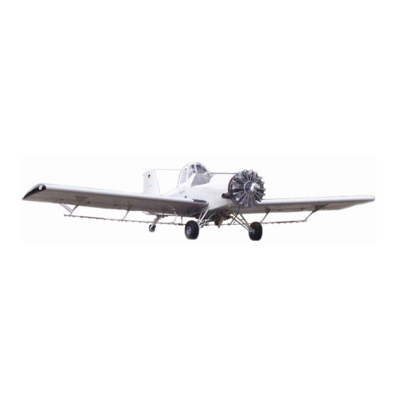
THRUSH AIRCRAFT S2R-R1340 Manuals
Manuals and User Guides for THRUSH AIRCRAFT S2R-R1340. We have
1
THRUSH AIRCRAFT S2R-R1340 manual available for free PDF download: Maintenance Manual
THRUSH AIRCRAFT S2R-R1340 Maintenance Manual (227 pages)
SINGLE COCKPIT AND DUAL COCKPIT
Brand:
THRUSH AIRCRAFT
| Category:
Aircrafts
| Size: 9.08 MB
Table of Contents
General Information
9
Table of Contents
9
General Description
10
Contact Information
10
Principal Dimensions
10
General
10
Weight & Balance
10
Wing
11
Horizontal Stabilizer and Elevators
11
Vertical Stabilizer and Rudder
11
Areas
11
Supplier Furnished Component Manuals
12
Aircraft Structure
12
Fuselage
12
Wing
12
Empennage
13
Cockpit
13
Aircraft Systems
13
Hydraulic Systems
13
Power Plant & Propeller
13
Fuel System
13
Landing Gear, Wheels & Brakes
14
Flight Controls
14
Instruments
15
Electrical System
15
Aircraft Weight & Balance
15
Figure 1-1: Aircraft 3-View
16
Figure 1-2: Aircraft Stations
17
Servicing & Inspection
19
Servicing & Inspection
21
Ground Handling
21
Jacking
21
Leveling
21
Mooring
21
Parking
21
Taxiing
21
Towing
21
Calculated Weight
22
Weighing
22
Weighing the Airplane
23
Cold Weather Operation
23
Cold Weather Maintenance Hints
24
Ground Operation of Engine
24
Exterior Pre-Start Check
25
Pre-Start Checklist
25
Cockpit Pre-Start Check
25
Starting Engine
25
Engine Operational Checks
26
Ground Emergency Procedures
24
Engine Fires
24
Electrical Fires
24
System and Component Servicing
27
Hydraulic System
27
Engine Oil System
27
Engine Air Induction and Filter Cleaning
28
Fuel System
28
Defueling
30
Landing Gear, Wheels & Brakes
30
Mlg Shock Struts
30
Tires
30
Brake Bleeding
31
Engine Depreservation
31
Engine Preservation Procedure
31
Inspection
40
Inspection Check List
40
General Instructions
40
A: Propeller
41
B: Engine Externals
41
C: Engine Oil System
42
D: Engine Fuel System
43
E: Air Induction System
43
F: Airframe Fuel System
44
G: Ignition System
45
H: Main Landing Gear
45
J: Hydraulic System
46
K: Tail Gear
46
L: Fuselage Skins
48
M: Hopper
48
N: Wings
48
P: Fuselage Frame
49
Q: Control Systems
50
R: Empennage
51
S: Ailerons and Flaps
51
T: Cockpit
52
U: Electrical System
52
Battery Maintenance
53
Airframe Maintenance
53
Corrosion Control
53
Windshield
54
Hopper Repair
54
Fuel Tank Repair
54
Lubrication
56
Table of Contents
65
General Description
66
Hydraulic System
66
Master Cylinder
66
Brake System Bleeding
68
Parking Brakes
70
Power Plant and Propeller
71
Ignition System
73
Magneto Removal
73
Magneto Timing and Installation
73
Timing and Synchronizing Magnetos
73
Ignition Conduit Lead Replacement
78
Powerplant General
73
Oil System
79
Pressure Relief Valve
80
Pressure Oil Strainer
80
Installing Oil Strainer
80
Pre-Oiling
80
Pre-Oiling (Optional)
81
Carburetor
81
Carburetor Removal
81
Carburetor Installation
81
Cleaning Fuel Strainer
82
Starter
82
Starter Removal
83
Starter Installation
83
Alternator
83
Alternator Removal
83
Alternator Installation
83
Fuel Pump
83
Fuel Pump Removal
83
Fuel Pump Installation
83
Propeller
84
Propeller Removal
84
Propeller Installation
85
Propeller Governor
88
Propeller Governor Installation
88
Propeller Governor Removal
88
Propeller Ground Test
88
Engine Change
89
Engine Removal
89
Engine Buildup
90
Engine Installation
91
Initial Engine Ground Run
91
Engine Controls
92
Rigging
92
Engine Mount
92
Oil Cooler
92
Oil Cooler Removal
92
Oil Cooler Installation
92
Exhaust System
93
Exhaust Ring Removal
93
Exhaust Ring Installation
94
Engine Conditioning Hints
94
Ignition
94
Fuel System
109
General Description
110
Maintenance Precautions
111
Fuel Sub-Systems and Components
112
Fuel Quantity Indicator
112
Fuel Quantity Transmitter
112
Fuel Tank Vent System
112
Fuel Quantity Indicating System Calibration
113
Installation
113
Removal
113
Auxiliary Fuel Pump
115
Auxiliary Fuel Pump Installation
115
Auxiliary Fuel Pump Removal
115
FUEL Strainer
115
Fuel Strainer Service Instructions
116
FUEL System MAINTENANCE and Repair
116
Figure 5-2: Fuel Vent System
113
Figure 5-3: R1340 Fuel Quantity Gauge
115
Use of Fuel Proof Sealants
116
Leak Sealing
118
Figure 5-4: Proper Application of Fuel Proof Sealant
118
Fuel Tank Pressure Check
119
Fuel Tank Set-Up
119
Required Equipment
119
Pressure Check Procedure
120
Pressure Check Set-Up
120
Fuel System Troubleshooting
121
Table 5-2: Fuel System Trouble Shooting Chart
124
Activating Hopper (Ferry) Fuel System
124
Operating Instructions for the P/N 60167 Ferry Fuel System
124
Section 6
127
Main Landing Gear
128
Landing Gear, Wheels & Brakes
128
Main Landing Gear Assembly
128
Cleaning, Inspection and Repair of Main Gear
128
Removal
128
Cleaning, Inspection and Repair of Shock Struts
129
General Description
129
Main Wheel Removal and Disassembly
129
Inspection of Main Wheel Assembly
131
Main Wheel REASSEMBLY and INSTALLATION
132
Brake Removal and Disassembly
133
Brake Servicing
134
Measuring Brake Lining Wear
134
Removal of Brake Linings from Calipers
134
Replacement of Organic Linings
134
Brake Lining Conditioning Procedures
136
Non-Asbestos Organic Linings
136
Reassembly of Organic Linings to Caliper
136
Brake Reassembly and Installation
137
Brake Bleeding
138
Disassembly and Repair
138
Master Cylinder Installation
138
Removal of Brake Master Cylinders
138
Main Wheels and Brakes
129
General Description
128
Tail Landing Gear
138
Tail Gear Removal
138
Cleaning, Inspection and Repair of Tail Landing Gear
139
Tail Landing Gear INSTALLATION
139
Cleaning, Inspection and Repair of Tail Gear Spindle Housing Assembly
141
Disassembly of Spindle Housing Assembly
141
TAIL Landing GEAR RIGGING
141
Inspection of Tail Landing Gear Wheel Assembly
142
TAIL Gear WHEEL and Tire REMOVAL and DISASSEMBLY
142
TAIL Landing Gear WHEEL & Tire REASSEMBLY and INSTALLATION
143
Wheel and Brake Troubleshooting
145
Flight Controls
147
General Description
149
General Maintenance of Flight Controls
149
Aileron Control System
150
Control Stick
150
Control Stick, Fork and Torque Tube Removal
150
Control Stick, Fork and Torque Tube Installation
150
Aileron Control Linkage
150
Aileron Rigging
152
Aileron Servo Tabs
153
Aileron
153
Flap Jackscrew Removal
154
Flap Removal
155
Flap Installation
155
Flap Rigging
155
Rudder Removal
156
Rudder Installation
156
Rudder Pedal Removal
156
Control Cables Removal
156
Rudder Control Cables Installation
157
Rudder Rigging
158
Rudder Trim Tab
158
Balance Cable Rigging
158
Elevators
158
Elevator down Spring
158
Elevator Removal
158
Elevator Installation
158
Elevator Rigging
159
Elevator Trim Tabs
160
Elevator Trim Tab Removal
160
Elevator Trim Tab Rigging
161
Empennage
161
Empennage Removal
161
Empennage Installation
161
Horizontal Stabilizer
161
Vertical Stabilizer
163
Wings
164
Wing Removal
164
Wing Installation
166
Wing Installation When the Wing Attach Angles Are Replaced
170
Aileron System
172
Flap System
172
Rudder System
173
Elevator System
174
Elevator Trim System
174
Flight Control Static Balance Limits
175
Instruments
177
Flight Instruments
178
Pitot-Static System
178
Inspection and Leakage Test
179
Maintenance
179
Altimeter
181
Airspeed Indicator
181
Magnetic Compass
181
Magnetic Compass Compensation
182
Turn Coordinator
182
General Description
178
Instrument System Maintenance
178
Power Plant Instruments
183
Oil Temperature System
183
Oil Pressure System
183
Fuel Pressure System
184
Manifold Pressure System
184
Tachometer System
184
Voltmeter
185
Ammeter
186
HOPPER QUANTITY (Optional Equip.)
186
Calibration of Hopper Quantity Gauge
187
Instrument Troubleshooting
187
Airspeed Indicator
188
Altimeter
188
Magnetic Compass
189
Engine Oil Pressure Gauge
189
Engine Fuel Pressure Gauge
190
Tachometer
190
Fuel Quantity Indicator
191
Engine Oil Temperature Gauge
191
Dispersal Systems
195
General Description
196
Dispersal Systems
196
Hopper
196
Hopper Care
196
Hopper Repair
197
Hopper Gate Box Removal
198
Hopper Gate Box Installation
198
Spray Dispersal System
199
Dispersal System Maintenance
199
Agitator and Spreader
200
Electrical System
203
General Description
204
Power Distribution
204
Battery and External Power
204
Battery Servicing
204
Servicing Battery Installed in Aircraft
205
Battery Operation
205
Battery Removal
205
Battery Installation
205
Alternator System
206
Voltage Regulator Removal
206
Voltage Regulator Installation
206
Table 10-1: Electrical Troubleshooting Chart
210
Battery System
210
Starter
211
Advertisement
Advertisement
Related Products
Thrush Aircraft S2RHG-T65 TURBO THRUSH
THRUSH AIRCRAFT S2R-T660
THRUSH AIRCRAFT Categories
Aircrafts
More THRUSH AIRCRAFT Manuals
Login
Sign In
OR
Sign in with Facebook
Sign in with Google
Upload manual
Upload from disk
Upload from URL