Sign In
Upload
Manuals
Brands
Texas Instruments Manuals
Motherboard
TPS25751EVM
Texas Instruments TPS25751EVM Manuals
Manuals and User Guides for Texas Instruments TPS25751EVM. We have
1
Texas Instruments TPS25751EVM manual available for free PDF download: User Manual
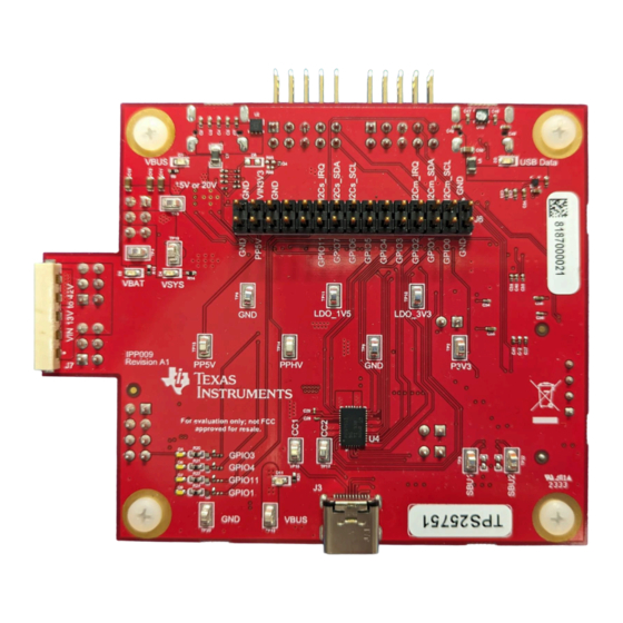
Texas Instruments TPS25751EVM User Manual (56 pages)
Brand:
Texas Instruments
| Category:
Motherboard
| Size: 10.91 MB
Table of Contents
Description
1
Get Started
1
Table of Contents
2
Features
1
Applications
1
1 Evaluation Module Overview
4
Introduction
4
Kit Contents
4
Specification
4
Device Information
4
Figure 1-1. TPS25751EVM Block Level Diagram
4
Table 1-1. Devices on TPS25751EVM
4
2 Hardware
5
Power Requirements
5
Setup
5
Header Information
5
Figure 2-1. J6 Header
5
Table 2-1. J6 Header Pinout
6
Jumper Information
7
Figure 2-2. Jumper Locations
7
Table 2-2. Jumper Descriptions
7
LED Information
8
Test Points
8
Switches/Push Buttons
8
Table 2-3. Leds
8
Table 2-4. Test Points
8
Table 2-5. Switches/Push Buttons
8
3 Software
9
Software Description
9
Figure 3-1. Application Customization Tool Download
9
Software Development
10
Using the TPS25751 Application Customization Tool
10
Figure 3-2. Application Customization Tool Configuration
11
Table 3-1. TPS25751 Configuration
11
Figure 3-3. Enabling Advanced Configuration
14
Figure 3-4. Using Advanced Configuration
14
Figure 3-5. TPS25751EVM Connection with PC
15
Figure 3-6. Serial Port Configuration Settings
16
Figure 3-7. Flash to Device from Current Configuration
16
Figure 3-8. Flash to Device from Current Configuration
17
Figure 3-9. Flash to Device from Current Configuration
17
Figure 3-10. Resetting Configuration
18
Figure 3-11. Export Settings in Application Customization Tool
19
Figure 3-12. Import Settings in Application Customization Tool
20
Figure 3-13. Generating Binary Configuration Using the Application Customization Tool
21
4 Application Specific Use Case
23
Application Specific General Overview
23
TPS25751EVM and Bq257Xxevm Setup
23
Figure 4-1. J1 Jumper for BQ Setups
23
Figure 4-2. Ribbon Cable Connection to J11
24
Figure 4-3. TPS25751EVM and BQ25756(E)EVM Hardware
24
Figure 4-4. TPS25751EVM and BQ25792/8EVM Hardware
26
Table 4-1. TPS25751EVM and BQ25792/8EVM Connections
26
Table 4-2. TPS25751EVM and BQ25713EVM Connections
28
Liquid Detection and Corrosion Mitigation Overview
30
Table 4-3. Liquid Detection Test Points
32
Table 4-4. Liquid Detection/Corrosion Mitigation Default Configuration
32
5 Hardware Design Files
33
Schematics
33
PCB Layouts
39
Bill of Materials (BOM)
43
Table 5-1. Bill of Materials
43
6 Additional Information
49
Trademarks
49
Electrostatic Discharge Caution
49
Terminology
49
Device Support
49
Documentation Support
49
Receiving Notification of Documentation Updates
50
Support Resources
50
7 Revision History
50
Advertisement
Advertisement
Related Products
Texas Instruments TPS25741EVM-802
Texas Instruments TPS25741AEVM-802
Texas Instruments TPS25740EVM-741
Texas Instruments TPS25740AEVM-741
Texas Instruments TPS25730
Texas Instruments TPS25730D
Texas Instruments TPS2596EVM
Texas Instruments TPS2596
Texas Instruments TPS25831Q1EVM-062
Texas Instruments TPS25980EVM
Texas Instruments Categories
Motherboard
Control Unit
Microcontrollers
Computer Hardware
Calculator
More Texas Instruments Manuals
Login
Sign In
OR
Sign in with Facebook
Sign in with Google
Upload manual
Upload from disk
Upload from URL