Sign In
Upload
Manuals
Brands
Terex Manuals
Boom Lifts
Genie Z13505-101
Terex Genie Z13505-101 Manuals
Manuals and User Guides for Terex Genie Z13505-101. We have
1
Terex Genie Z13505-101 manual available for free PDF download: Service And Repair Manual
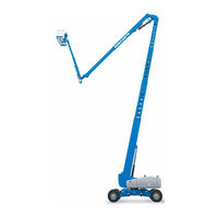
Genie Genie Z13505-101 Service And Repair Manual (253 pages)
Brand:
Genie
| Category:
Boom Lifts
| Size: 8.14 MB
Table of Contents
October
2
Find a Manual for this Model
2
Serial Number Legend
4
Safety Rules
5
Table of Contents
7
Specifications
13
Machine Specifications
13
Performance Specifications
13
Hydraulic Oil Specifications
14
Hydraulic Component Specifications
17
Deutz TD 2.9 Engine Specifications
19
Deutz Td2011L04I Engine Specifications
20
Perkins 854F-34T Engine Specifications
22
Perkins 1104D-44T Engine Specifications
24
Machine Torque Specifications
26
Hydraulic Hose and Fitting Torque Specifications
27
Torque Procedure
28
Repair Procedures
31
Introduction
31
About this Section
32
Platform Controls
33
Platform Circuit Board
34
How to Remove the LED Circuit Board
35
Joysticks - How to Calibrate a Joystick
35
How to Reset a Proportional Valve Coil Default
39
How to Set the Function Thresholds and Default Functions Speeds
40
How to Adjust the Function Speeds
42
How to Adjust the Function Ramp Rate Setting
43
Press the Enter Button to Save the Setting in Memory
43
Press the Enter or Previous Button on the LCD Screen until EXIT Is Displayed
43
Press the Plus Button or Minus Button to
43
Select YES and then Press the Enter Button
43
Platform Components
44
Platform
44
Platform Leveling Cylinder
45
Specifications
45
October
45
Platform Rotator
46
How to Bleed the Platform Rotator
47
Platform Level Sensor - How to Calibrate the Platform Level Sensor
48
Platform Overload System (if Equipped)
49
Platform Overload Recovery Message
51
Jib Boom Components
52
Jib Boom Cable Track
53
How to Repair the Cable Track
55
Jib Boom
56
Note: Perform this Procedure with the Boom in the
56
Stowed Position
56
Jib Boom Lift Cylinder
58
Jib Boom Level Cylinder
59
Jib Boom Extension Cylinder
60
Angle Sensor
62
Note: Use the Following Chart to Identify the Description of each LCD Screen Control Button Used in this Procedure
63
Boom Components
68
Primary Boom Cable Track
69
How to Repair the Primary Boom Cable Track
71
Secondary Boom Cable Track
72
How to Repair the Secondary Boom Cable Track
74
Primary Boom
75
Primary Boom Lift Cylinder
77
Secondary Boom Lift Cylinder
78
Primary Boom Extension Cylinder
82
Secondary Boom Extension Cylinders
83
Sensor
85
Secondary Boom Angle Sensor - How to Calibrate the Secondary Boom Angle Sensor
90
Engines
96
RPM Adjustment
96
Flex Plate
96
How to Install the Flex Plate
97
Ground Controls
98
Bypass/Recovery Key Switch
98
How to Use the Recovery Mode
100
Circuit Boards
101
Membrane Decal
103
Full Machine Calibration
104
Display Module
105
Hydraulic Pumps
114
Function Pump
114
How to Prime the Function Pump
115
How to Adjust the Function Pump Standby Pressure
115
How to Adjust the Function Pump Pressure Compensator
116
Drive Pump
117
How to Prime the Drive Pump
118
Manifolds
120
Function Manifold Components
120
Valve Adjustments - Function Manifold
124
Platform Manifold
126
Jib Boom Manifold
128
Flow Control Mainfold
130
Function Enable Valve
131
Turntable Rotation Manifold
132
Steer and Axle Manifold
134
Valve Adjustments - Steer and Axle Manifold
138
Traction Manifold Components
140
Valve Adjustments - Traction Manifold
144
Drive Oil Diverter Manifold Components (Welder Option)
145
Valve Coils
146
Turntable Rotation Components
148
Turntable Rotation Assembly
148
How to Adjust the Turntable Rotation Gear Backlash
149
Turntable Level Sensor - How to Calibrate the Turntable Level Sensor
150
Axle Components
153
Steer Sensors
153
How to Calibrate a Replacement Steer Sensor
155
How to Calibrate All Steer Sensors
156
October
156
Steer Cylinders
158
Axle Extension Cylinders
159
Axle Angle Sensors - How to Calibrate the Axle Angle Sensors
160
Fault Codes
163
Introduction
163
Section 4 Fault Codes
163
Control System Fault Codes
164
Fault Matrix
181
Deutz TD 2.9 L4 Engine Fault Codes
182
Perkins 854F-34T Engine Fault Code
197
Schematics
205
Introduction
205
Section 5 Schematics
205
Wire Circuit Legend
206
Wire Color Legend
210
Limit Switches and Angle Sensors
215
Circuit Connector Legend
219
Drive Chassis and Platform Controller Pin Legend
222
Safety Controller Pin Legend
223
Turntable Controller Pin Legend
224
Telematics Connector Pin Legend
225
Engine Relay and Fuse Panel Legend - Deutz Td2011L04I
226
Engine Relay and Fuse Panel Legend - Deutz TD2.9
227
Engine Relay and Fuse Panel Legend - Perkins 1104D-44T
228
Engine Relay and Fuse Panel Legend - Perkins 854F-34T
229
Electrical Symbols Legend
230
Hydraulic Symbols Legend
231
Perkins 1104D Engine Electrical Schematic
234
Perkins 854F-34T Engine Electrical Schematic
236
Perkins 854F-34T Engine Harness
237
Deutz TD2.9 Engine Electrical Schematic
240
Deutz TD2.9 Engine Harness
241
Hydraulic Generator (Welder Option)
244
Generator Wiring Schematic
245
Hydraulic Schematic (to SN ZX13516H-2804)
248
Hydraulic Schematic (from SN ZX13516H-2805)
249
Electrical Schematic
251
Electrical Schematic
252
Advertisement
Advertisement
Related Products
Terex Genie Z-135/70
Terex Genie Z13513-2000
Terex Genie Z-135
Terex Genie Z-34/22N
Terex Z34F-14000
Terex Genie Z-60DC
Terex Genie Z6216N-2999
Terex Genie Z-40N
Terex Genie Z-22
Terex Genie Z6216D-136
Terex Categories
Boom Lifts
Lifting Systems
Construction Equipment
Scissor Lifts
Compact Loader
More Terex Manuals
Login
Sign In
OR
Sign in with Facebook
Sign in with Google
Upload manual
Upload from disk
Upload from URL