Sign In
Upload
Manuals
Brands
Sony Manuals
Camcorder
Handycam DCR-PC100
Sony Handycam DCR-PC100 Manuals
Manuals and User Guides for Sony Handycam DCR-PC100. We have
7
Sony Handycam DCR-PC100 manuals available for free PDF download: Service Manual, Operating Instructions Manual, User Manual, Limited Warranty
Sony Handycam DCR-PC100 Service Manual (215 pages)
DIGITAL VIDEO CAMERA RECORDER
Brand:
Sony
| Category:
Camcorder
| Size: 23.84 MB
Table of Contents
Table of Contents
3
Service Note
6
Power Supply During Repairs
6
To Take out a Cassette When Not Eject
6
Self-Diagnosis Function
7
Self-Diagnosis Display
7
Service Mode Display
7
Display Method
7
Switching of Backup no
7
End of Display
7
Self-Diagnosis Code Table
8
2 Disassembly
53
Lcd Unit, Pd-125 Board
53
MD Block-1
54
Board, MD Block-2
55
Lens Assembly, Evf Block Assembly, Control Switch Block (Me-4950)
56
VC-227P) Board, Speaker, Memory Stick Connector, Microphone Unit
56
Board
56
Hinge Assembly
57
DC-In Connector, Battery Terminal Board
57
Board
58
Assembly
59
Board, Vf Holder Assembly
59
Eye Cup Assembly
59
Control Switch Block (Fk-4950)
62
Flexible Boards Location
62
Block Diagrams
63
Overall Block Diagram-1
63
Overall Block Diagram-2
64
Overall Block Diagram-3
65
Power Block Diagram-1
66
Power Block Diagram-2
67
Printed Wiring Boards and Schematic Diagrams
68
Frame Schematic Diagram-1
68
Frame Schematic Diagram-2
69
Schematic Diagrams
70
Printed Wiring Board
70
A/D Converter
74
Camera Signal Processor
75
Jpeg, Digital Still Control
76
Agc, Afc, Nd Cont (Bbi
78
Line out Amp
79
Vfd
80
Sfd
81
Lip/Tfd
82
Focus/Zoom Motor Control
83
Camera Control
84
Mode Control
85
Hi Control)
86
Audio
87
DC/DC Converter
88
Memory Stick I/F, Agc, Afc, Line out Amp
89
Mode Control, Hi Control, Audio
89
Printed Wiring Board
89
Panel Open)
90
Flexible Board
90
Drive, Timing Generator, Rec/Pb Head Amp, Laser Link)
91
Printed Wiring Board
91
Mode), Fp-92 (Top/End Sensor, Tape Led), Fp-242 (S/T Reel Sensor) Printed Wiring Boards
92
Connector
93
Drum/Capstan Motor Drive
94
ID Detect, Timing Generator
95
Rec/Pb Head Amp
96
Laser Link
97
Video In/Out, DC in
98
Printed Wiring Board
99
Control Switch Block (Fk-4950)
101
Control Switch Block (Me-4950)
101
MIC Amp
104
Printed Wiring Board
105
Rgb Driver, Tg
105
Rgb Driver
106
Lcd Driver
108
Back Light Driver
109
Lcd Driver, Back Light Driver
110
Printed Wiring Board
110
Waveforms
112
Mounted Location
115
Adjustments
120
Before Starting Adjustment
120
Adjusting Items When Replacing Main Parts and Boards
121
Camera Section Adjustment
123
Preparations before Adjustment
123
List of Service Tools
123
Preparations
124
Precaution
126
Setting the Switch
126
Order of Adjustments
126
Subjects
126
Initialization of B, C, D, E, F, 7 Page Data
127
Initialization of C Page Data
127
Modification of C Page Data
127
Modification of D Page Data
129
Initialization of B Page Data
131
Initializing the E, F, 7 Page Data
132
Modification of E, F, 7 Page Data
132
Page Table
138
Camera System Adjustments
140
Mhz/66Mhz Origin Oscillation Adjustment
140
(CD-234 Board)
140
Zoom Key Center Adjustment
140
HALL Adjustment
141
MR Adjustment
141
Flange Back Adjustment
142
More than 500M Away)
143
Flange Back Adjustment (1)
143
Flange Back Adjustment (2)
143
Flange Back Check
144
Picture Frame Setting
144
Color Reproduction Adjustment
145
MAX GAIN Adjustment
146
Auto White Balance & LV Standard Data Input
146
Auto White Balance Adjustment
147
White Balance Check
147
Mechanical Shutter Data Input
148
Angular Velocity Sensor Sensitivity Adjustment
148
Color Electronic Viewfinder
149
System Adjustment
149
VCO Adjustment (VF-138 Board)
149
Bright Adjustment (VF-138 Board)
150
Contrast Adjustment (VF-138 Board)
150
White Balance Adjustment (VF-138 Board)
151
Lcd System Adjustment
152
VCO Adjustment (PD-125 Board)
152
Black Limit Adjustment (PD-125 Board)
153
Bright Adjustment (PD-125 Board)
153
Gamma-1 Adjustment (PD-125 Board)
154
Contrast Adjustment (PD-125 Board)
154
Center Level Adjustment (PD-125 Board)
155
White Balance Adjustment (PD-125 Board)
155
Mechanism Section Adjustment
156
How to Enter Record Mode Without
156
Cassette
156
How to Enter Playback Mode
156
Without Cassette
156
Tape Path Adjustment
156
Preparation for Adjustment
156
Processing after Completing Operations
156
Video Section Adjustment
157
Preparations before Adjustments
157
Equipment to Required
157
Precautions on Adjusting
158
Adjusting Connectors
159
Connecting the Equipment
159
Checking the Input Signals
159
Alignment Tapes
160
Input/Output Level and Impedance
160
System Control System Adjustment
161
Initialization of B, C, D, E, F, 7 Page Data
161
Serial No. Input
161
Company ID Input
161
Battery End Check (VC-227 Board)
163
Servo and Rf System Adjustment
164
Cap FG Duty Adjustment (VC-227 Board)
164
T Reel FG Duty Adjustment (VC-227 Board)
164
PLL F & LPF F
164
Switching Position Adjustment (VC-227 Board)
165
AGC Center Level and APC & AEQ Adjustment
165
Preparations before Adjustments
165
AGC Center Level Adjustment (VC-227 Board)
165
APC & AEQ Adjustment (VC-227 Board)
166
Processing after Completing Adjustments
166
PLL F & LPF F
166
Video System Adjustments
167
Base Band Block Adjustments
167
Chroma BPF F Adjustment (VC-227 Board)
167
S VIDEO out y Level Adjustment (VC-227 Board)
167
S VIDEO out Chroma Level Adjustment
168
(VC-227 Board)
168
AV out Y, Chroma Level Check (VC-227 Board)
168
PLL Adjustment (VC-227 Board)
169
BIST Check
170
Playback System Check
170
Preparation for Playback
170
IC1900(TRX) bist(PB) Check
170
IC1601(TFD) bist(PB) Check
170
IC1600(SFD) bist(PB) Check
170
IC1501(VFD) bist(PB) Check
171
Recording System Check
172
Preparations for Recording
172
IC1501(VFD) bist(REC) Check
172
IC1600(SFD) bist(REC) Check
172
IC1601(TFD) bist(REC) Check
173
IC1900(TRX) bist(REC) Check
173
Ir Transmitter Adjustments
174
IR Video Carrier Frequency Adjustment
174
(MR-44 Board)
174
IR Video Deviation Adjustment (MR-44 Board)
174
IR Audio Deviation Adjustment (MR-44 Board)
175
Audio System Adjustments
176
Playback Level Check
177
Overall Level Characteristics Check
177
Overall Distortion Check
177
Overall Noise Level Check
177
Overall Separation Check
177
Service Mode
178
Adjustment Remote Commander
178
Using the Adjustment Remote Commander
178
Remote Commander
180
Service Mode
180
Setting the Test Mode
180
Emergence Memory Address
180
EMG Code (Emergency Code)
180
MSW Code
181
Bit Value Discrimination
182
Switch Check (1)
182
Switch Check (2)
183
Record of Use Check
183
Repair Parts List
184
Exploded Views
184
Cabinet (R) Section-1
184
Cabinet (R) Section-2
185
Cabinet (R) Section-3
186
Cabinet (L) Block Assembly
187
Lens Assembly, Evf Block Assembly
188
Cassette Compartment and Drum Assy
189
Ls Chassis Section
190
Mechanism Chassis Block Section-1
191
Mechanism Chassis Block Section-2
192
Electrical Parts List
193
Advertisement
Sony Handycam DCR-PC100 Service Manual (194 pages)
Brand:
Sony
| Category:
Camcorder
| Size: 18.03 MB
Table of Contents
Table of Contents
3
Service Note
6
Power Supply During Repairs
6
To Take out a Cassette When Not Eject
6
Self-Diagnosis Function
7
Self-Diagnosis Display
7
Service Mode Display
7
Display Method
7
Switching of Backup no
7
End of Display
7
Self-Diagnosis Code Table
8
2 Disassembly
53
Lcd Unit, Pd-125 Board
53
MD Block-1
54
Board, MD Block-2
55
Lens Assembly, Evf Block Assembly, Control Switch Block (Me-4950)
56
VC-227P) Board, Speaker, Memory Stick Connector, Microphone Unit
56
Board
56
Hinge Assembly
57
DC-In Connector, Battery Terminal Board
57
Board
58
Assembly
59
Board, Vf Holder Assembly
59
Eye Cup Assembly
59
Control Switch Block (Fk-4950)
62
Flexible Boards Location
62
Block Diagrams
63
Overall Block Diagram-1
63
Overall Block Diagram-2
64
Overall Block Diagram-3
65
Power Block Diagram-1
66
Power Block Diagram-2
67
Printed Wiring Boards and Schematic Diagrams
68
Frame Schematic Diagram-1
68
Frame Schematic Diagram-2
69
Schematic Diagrams
70
Printed Wiring Board
70
Drive, Timing Generator, Rec/Pb Head Amp, Laser Link)
71
Printed Wiring Board
71
Mode), Fp-92 (Top/End Sensor, Tape Led), Fp-242 (S/T Reel Sensor) Printed Wiring Boards
76
Connector
77
Drum/Capstan Motor Drive
78
ID Detect, Timing Generator
79
Rec/Pb Head Amp
80
Laser Link
81
Video In/Out, DC in
83
Video In/Out, DC in
84
Control Switch Block (Fk-4950)
85
Control Switch Block (Me-4950)
85
MIC Amp
87
Rgb Driver, Tg
89
Rgb Driver
90
Lcd Driver
92
Back Light Driver
93
Lcd Driver, Back Light Driver
94
Waveforms
96
Mounted Location
99
Adjustments
104
Before Starting Adjustment
104
Adjusting Items When Replacing Main Parts and Boards
105
Camera Section Adjustment
107
Preparations before Adjustment
107
List of Service Tools
107
Preparations
108
Precaution
110
Setting the Switch
110
Order of Adjustments
110
Subjects
110
Initialization of B, C, D, E, F, 7 Page Data
111
Initialization of C Page Data
111
Modification of C Page Data
111
Modification of D Page Data
113
Initialization of B Page Data
115
Initializing the E, F, 7 Page Data
116
Modification of E, F, 7 Page Data
116
Modification of F Page Data
117
Page Table
122
Camera System Adjustments
124
Mhz/66Mhz Origin Oscillation Adjustment
124
(CD-234 Board)
124
Zoom Key Center Adjustment
124
HALL Adjustment
125
MR Adjustment
125
Flange Back Adjustment
126
More than 500M Away)
127
Flange Back Adjustment (1)
127
Flange Back Adjustment (2)
127
Flange Back Check
128
Picture Frame Setting
128
Color Reproduction Adjustment
129
MAX GAIN Adjustment
130
Auto White Balance & LV Standard Data Input
130
Auto White Balance Adjustment
131
White Balance Check
131
Mechanical Shutter Data Input
132
Angular Velocity Sensor Sensitivity Adjustment
132
Color Electronic Viewfinder
133
System Adjustment
133
VCO Adjustment (VF-138 Board)
133
Bright Adjustment (VF-138 Board)
134
Contrast Adjustment (VF-138 Board)
134
White Balance Adjustment (VF-138 Board)
135
Lcd System Adjustment
136
VCO Adjustment (PD-125 Board)
136
Black Limit Adjustment (PD-125 Board)
137
Bright Adjustment (PD-125 Board)
137
Gamma-1 Adjustment (PD-125 Board)
138
Contrast Adjustment (PD-125 Board)
138
Center Level Adjustment (PD-125 Board)
139
White Balance Adjustment (PD-125 Board)
139
Mechanism Section Adjustment
140
How to Enter Record Mode Without
140
Cassette
140
How to Enter Playback Mode
140
Without Cassette
140
Tape Path Adjustment
140
Preparation for Adjustment
140
Processing after Completing Operations
140
Video Section Adjustment
141
Preparations before Adjustments
141
Equipment to Required
141
Precautions on Adjusting
142
Adjusting Connectors
143
Connecting the Equipment
143
Checking the Input Signals
143
Alignment Tapes
144
Input/Output Level and Impedance
144
System Control System Adjustment
145
Initialization of B, C, D, E, F, 7 Page Data
145
Serial No. Input
145
Company ID Input
145
Battery End Check (VC-227 Board)
147
Servo and Rf System Adjustment
148
Cap FG Duty Adjustment (VC-227 Board)
148
T Reel FG Duty Adjustment (VC-227 Board)
148
Switching Position Adjustment (VC-227 Board)
149
AGC Center Level and APC & AEQ Adjustment
149
Preparations before Adjustments
149
APC & AEQ Adjustment (VC-227 Board)
150
Processing after Completing Adjustments
150
PLL F & LPF F
150
Video System Adjustments
151
Base Band Block Adjustments
151
Chroma BPF F Adjustment (VC-227 Board)
151
S VIDEO out y Level Adjustment (VC-227 Board)
151
S VIDEO out Chroma Level Adjustment
152
(VC-227 Board)
152
AV out Y, Chroma Level Check (VC-227 Board)
152
PLL Adjustment (VC-227 Board)
153
BIST Check
154
Playback System Check
154
Preparation for Playback
154
IC1900(TRX) bist(PB) Check
154
IC1601(TFD) bist(PB) Check
154
IC1600(SFD) bist(PB) Check
154
IC1501(VFD) bist(PB) Check
155
Recording System Check
156
Preparations for Recording
156
IC1501(VFD) bist(REC) Check
156
IC1600(SFD) bist(REC) Check
156
Ir Transmitter Adjustments
158
IR Video Carrier Frequency Adjustment
158
(MR-44 Board)
158
IR Video Deviation Adjustment (MR-44 Board)
158
IR Audio Deviation Adjustment (MR-44 Board)
159
Audio System Adjustments
160
Playback Level Check
161
Overall Level Characteristics Check
161
Overall Distortion Check
161
Overall Noise Level Check
161
Overall Separation Check
161
Service Mode
162
Adjustment Remote Commander
162
Using the Adjustment Remote Commander
162
Remote Commander
164
Service Mode
164
MSW Code
165
Switch Check (1)
166
Switch Check (2)
167
Record of Use Check
167
Repair Parts List
168
Exploded Views
168
Cabinet (R) Section-1
168
Cabinet (R) Section-2
169
Cabinet (R) Section-3
170
Cabinet (L) Block Assembly
171
Lens Assembly, Evf Block Assembly
172
Electrical Parts List
177
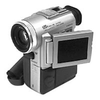
Sony Handycam DCR-PC100 Operating Instructions Manual (140 pages)
Digital Video Camera Recorder
Brand:
Sony
| Category:
Camcorder
| Size: 3.19 MB
Table of Contents
Digital Video Camera
1
Operating Instructions
1
Declaration of Conformity
2
Table of Contents
4
Checking Supplied Accessories
5
Quick Start Guide
6
Getting Started
8
Using this Manual
8
Precautions on Camcorder Care
9
Step 1 Preparing the Power Supply
10
Installing the Battery Pack
10
Charging the Battery Pack
11
Charging Time
12
Recording Time
12
Playing Time
12
Connecting to a Wall Outlet
13
Step 2 Inserting a Cassette
14
Recording - Basics
15
Recording a Picture
15
Adjusting the Lcd Screen
16
Adjusting the Brightness of the Lcd Screen
17
Adjusting the Viewfinder
18
Using the Zoom Feature
19
Start/Stop Mode Setting
20
Shooting Backlit Subjects (BACK LIGHT)
21
Shooting in the Dark (Nightshot)
22
Self-Timer Recording
23
End Search
24
Playback - Basics
25
Playing Back a Tape
25
Using the Data Code Function
27
Various Playback Modes
28
Viewing the Recording on TV
29
Advanced Recording Operations
31
Recording a Still Image on a Tape - Tape Photo Recording
31
Printing the Still Picture
33
Adjusting the White Balance Manually
34
Using the Wide Mode
35
Using the Fader Function
36
Using Special Effects - Picture Effect
38
Using Special Effects - Digital Effect
39
Using the PROGRAM AE Function
42
Adjusting the Exposure Manually
44
Focusing Manually
45
Advanced Playback Operations
46
Playing Back a Tape with Picture Effects
46
Playing Back a Tape with Digital Effects
47
Quickly Locating a Scene Using the Zero Set Memory Function
48
Searching the Boundaries of Recorded Tape by Title - Title Search
49
Searching a Recording by Date - Date Search
50
Searching for the Date Without Using Cassette Memory
51
Searching for a Photo - Photo Search/Photo Scan
52
Editing
54
Dubbing a Tape
54
Editing Partially on a DV Tape - DV Synchro-Editing
56
Recording Video or TV Programs
58
Inserting a Scene from a VCR - Insert Editing
62
Inserting a Scene from a Vcr – Insert Editing
63
Audio Dubbing
64
Dubbing with the Audio/Video Jack
65
Adding an Audio Sound on a Recorded Tape
66
Monitoring the New Recorded Sound
66
Superimposing a Title
68
Erasing a Title
71
Making Your Own Titles
72
Labeling a Cassette
74
Customizing Your Camcorder
76
Changing the Menu Settings
76
Resetting the Date and Time
83
?Memory Stick” Operations
84
Memory Stick" Operations
84
Using a "Memory Stick" - Introduction
84
Selecting Image Quality Mode
87
Image Quality Settings
88
Selecting the Image Size
89
Recording Still Images On"Memory Stick"S - Memory Photo Recording
91
Recording Images Continuously
92
Self-Timer Memory Photo Recording
94
Superimposing a Still Picture in a "Memory Stick" on a Moving Picture - MEMORY MIX
95
Recording an Image from a Mini DV Tape as a Still Image
98
Recording an Image from a Mini DV Tape as a Still Image
99
Copying Still Images from a Mini DV Tape - Photo Save
101
Viewing a Still Picture - Memory Photo Playback
103
Viewing a Still Picture – Memory Photo Playback
104
Copying the Image Recorded on "Memory Stick"S to Mini DV Tapes
106
Playing Back Images Continuously - SLIDE SHOW
108
Preventing Accidental Erasure - Image Protection
109
Deleting Images
110
Writing a Print Mark - PRINT MARK
113
Additional Information
114
Usable Cassettes
114
Audio Mode
115
Troubleshooting
116
Self-Diagnosis Display
122
Warning Indicators and Messages
123
Warning Messages
124
Using Your Camcorder Abroad
125
Maintenance Information and Precautions
126
Battery Pack
129
Specifications
130
Quick Reference
131
Identifying the Parts and Controls
131
Remote Commander
136
Operation Indicators
138
Quick Function Guide
139
Index
140
Advertisement
Sony Handycam DCR-PC100 Service Manual (105 pages)
DIGITAL VIDEO CAMERA RECORDER
Brand:
Sony
| Category:
Camcorder
| Size: 12.36 MB
Table of Contents
Table of Contents
3
Service Note
6
Power Supply During Repairs
6
To Take out a Cassette When Not Eject
6
Self-Diagnosis Function
7
Self-Diagnosis Display
7
Service Mode Display
7
Display Method
7
Switching of Backup no
7
End of Display
7
Self-Diagnosis Code Table
8
Disassembly
52
2-1. Lcd Unit, Pd-125 Board
53
MD Block-1
54
Board, MD Block-2
55
Lens Assembly, Evf Block Assembly, Control Switch Block (Me-4950)
56
VC-227P) Board, Speaker, Memory Stick Connector, Microphone Unit
56
Board
56
2-6. Hinge Assembly
57
DC-In Connector, Battery Terminal Board
57
FJ-25 Board
58
Assembly
59
Board, Vf Holder Assembly
59
Eye Cup Assembly
59
Circuit Boards Location
61
Flexible Boards Location
62
Block Diagrams
63
Overall Block Diagram-1
63
Overall Block Diagram-2
64
Overall Block Diagram-3
65
Power Block Diagram-1
66
Power Block Diagram-2
67
Printed Wiring Boards and Schematic Diagrams
68
Frame Schematic Diagram-1
68
Frame Schematic Diagram-2
69
Printed Wiring Board
70
A/D Converter
74
Camera Signal Processor
75
Jpeg, Digital Still Control
76
Sony Handycam DCR-PC100 User Manual (11 pages)
Digital Video Camera
Brand:
Sony
| Category:
Camcorder
| Size: 0.64 MB
Table of Contents
Camera Basics
2
Power Source
2
Lens Cover
4
Advanced Settings
7
Camera Menu Setting
8
Options Available
8
Sony Handycam DCR-PC100 Operating Instructions Manual (11 pages)
Serial Port Adaptor for MEMORY STICK
Brand:
Sony
| Category:
Receiver
| Size: 0.41 MB
Sony Handycam DCR-PC100 Limited Warranty (1 page)
Limited Warranty (U.S. Only)
Brand:
Sony
| Category:
Camcorder
| Size: 0.11 MB
Advertisement
Related Products
Sony DCR-PC1000
Sony Handycam DCR-PC1000E
Sony Digital Handycam DCR-PC100E
Sony DCR-PC101
Sony Handycam DCR-PC103E
Sony Handycam DCR-PC104E
Sony DCR-PC109 - Digital Handycam Camcorder
Sony HANDYCAM DCR-PC106E
Sony Handycam DCR-PC10
Sony DCR PC105 - Handycam Camcorder - 1.0 MP
Sony Categories
Laptop
TV
Camcorder
CD Player
Digital Camera
More Sony Manuals
Login
Sign In
OR
Sign in with Facebook
Sign in with Google
Upload manual
Upload from disk
Upload from URL