Sign In
Upload
Manuals
Brands
Siemens Manuals
Protection Device
Siprotec 7SD600
Siemens Siprotec 7SD600 Manuals
Manuals and User Guides for Siemens Siprotec 7SD600. We have
2
Siemens Siprotec 7SD600 manuals available for free PDF download: System Manual
Siemens Siprotec 7SD600 System Manual (170 pages)
Numerical line differential protection
Brand:
Siemens
| Category:
Protection Device
| Size: 0.87 MB
Table of Contents
Table of Contents
7
Figure 1.1 Line Differential Protection 7SD600 for Operation with Two Pilot Wires, Block Diagram
14
Introduction
14
Application
14
Features
15
Functional Scope
16
Design
18
Models
18
Dimensions
19
Figure 2.1 Dimensioned Drawing of 7XP20 for Panel Surface Mounting with Terminals on the Sides (Dimensions in MM)
19
Figure 2.2 Dimensioned Drawing of 7XP20 for Panel Surface Mounting with Terminals at Top and Bottom
20
Figure 2.3 Dimensioned Drawing of 7XP20 for Panel Flush Mounting or Cubicle Mounting (Dimensions in MM)
21
Summation Transformer 4AM4930
22
Figure 2.4 Dimensioned Drawing of the 4AM4930
22
Order Data
23
Table 2.1 Selection and Order Data
23
Technical Data
24
Table 3.1 General Device Data
24
Table 3.2 Mechanical Details
25
Standards and Directives
26
Table 3.3 Electrical Tests
26
Operating Conditions
28
Line Differential Protection
29
Figure 3.1 Stabilization Characteristic of the Differential Protection (Shown for Pre-Settings)
30
Remote Tripping
31
Lockout Function
31
Additional Functions
31
Table 3.7 Remote Tripping
31
Table 3.9 Additional Functions
31
Table 3.8 Lockout Function
31
Summation Transformer 4AM4930
32
Table 3.11 Summation Transformer 4AM4930
32
Figure 3.2 Summation Transformer 4AM4930
32
Method of Operation
34
Overall Function
34
Figure 4.1 Hardware Structure of the Line Differential Protection 7SD600
34
Table 4.1 Types of Faults and Winding Factors for Standard Connection L1-L3-E
36
Summation Transformer 4AM4930
36
Figure 4.2 Standard Connection of Summation Transformer 4AM4930
36
Line Differential Protection
38
Principle of Differential Protection
38
Stabilized Differential Protection
38
Figure 4.4 Basic Principle of Differential Protection
38
Formation of Measured Values for Line Differential Protection with Two Pilot Wires
39
Figure 4.5 Differential Protection with Two Pilot Wires - Flow Chart
39
Measured Value Processing
40
Figure 4.6 Stabilization Characteristic of the Differential Protection
40
Additional Stabilization in the Case of Current Transformer Saturation
41
Local Current Threshold
41
In-Rush Stabilization with Second Harmonic
41
Starting, Blocking and Tripping Logic
42
Figure 4.7 Simplified Logic Diagram of the Differential Protection
43
Pilot Wire Monitoring (Optional), Transfer Tripping, Remote Tripping
44
Pilot Wire Monitoring
44
Remote Tripping
45
Transfer Tripping
45
Figure 4.8 Coupling of Pilot Wire Monitoring
45
Figure 4.9 Logic Diagram of the Functions Related to the Pilot Wire Monitoring
47
Additional Functions
48
Processing of Events
48
Display and Binary Outputs (Signal Relay)
48
Information Via Display Panel or PC
48
Monitoring Functions
49
Hardware Monitoring
49
Measurement of Operational Values
49
State Interrogation
49
Disturbance Recording
49
Software Monitoring
50
Preparation Instructions
52
Packing and Unpacking the Device
52
Model 7SD600K-KEKKK for Panel Flush Mounting or Cubicle Mounting
53
Checking the Specified Ratings
53
Preparing for Operation
53
Models 7SD600K-KBKKK and -KDKKK for Panel Surface Mounting
53
Assembly and Connection
53
Auxiliary Supply
54
Control Voltage for Binary Input
54
Figure 5.1 Check Set Nominal Voltage of the Integrated Power Supply
55
Figure 5.2 Check of Selected Control Voltages of Binary Inputs 1 to 3 on the P.C.b
56
Standard Connection L1-L3-E
57
Connection Circuits
57
Checking the Connections
57
Connection for Reduced Earth-Fault Sensitivity
58
Connection for Increased Earth-Fault Sensitivity L1 - L3 - E
58
Figure 5.3 Standard Connection L1-L3-E
58
Figure 5.4 Connection L1-L2-L3 with Reduced Earth-Fault Sensitivity
58
Figure 5.5 Connection L1-L3-E with Increased Earth-Fault Sensitivity
58
Different Primary Nominal Currents
59
Two-Phase Connection
59
Figure 5.6 Matching Unequal Primary Currents
59
Figure 5.7 Two-Phase Connection L1 - L3
59
Demands on the Current Transformer
60
Demands on the Pilot Wires
60
Figure 5.8 Connection of Isolating Transformer 7XR9513
61
Setting the Operator and Memory Functions
62
Operating Conditions and General Information
62
Figure 5.9 Excerpt from the Menu Tree: Selection of Configuration Blocks
64
Settings for Integrated Operation - Block 71
65
Settings for the Serial Interface - Block 72
66
Settings for Fault Detection - Block 74
68
Configuring the Protective Functions
69
Introduction
69
Figure 5.10Excerpt from the Menu Tree: Selecting Configuration Block for the Protective Functions
69
Configuring the Functional Scope of the Device - Block 00
70
Marshalling of Binary Inputs, Binary Outputs and Displays
71
Introduction
71
Figure 5.11Excerpt from the Menu Tree: Example for Selecting Marshalling of Binary Inputs
72
Marshalling of the Binary Inputs - Block 61
73
Table 5.1 Marshallable Binary Input Functions
74
Marshalling of Signal Relay - Block 62
75
Table 5.2 Factory Set Binary Inputs
75
Marshalling of the Leds - Block 63
77
Table 5.3 Marshallable Binary Output Functions
77
Table 5.4 Factory Set Indications on Signal Relay
77
Table 5.5 Factory Set Leds
78
Marshalling of the Command Relays - Block 64
79
Table 5.6 Factory Set Command Functions
80
Operating Instructions
82
Safety Measures
82
Operating the Device
82
Membrane Keypad/Display Panel
82
Operation with a PC
83
Prerequisites for Operation
83
Front View of the Device
84
Figure 6.1 Front View of 7SD600 with Control Panel and Displays
84
Setting of Function Parameters
85
Introduction
85
Procedure for Parameterization
85
Figure 6.2 Selection of Parameters for the System and Station Data
85
Setting Date and Time
87
Initial Display
88
System and Station Data - Block 01
89
Settings for the Line Differential Protection
91
Figure 6.3 Trip Characteristic of the 7SD600
92
Settings for the Pilot Wire Monitoring
95
Settings for the Remote Tripping
96
Settings for Tripping on Receiving Remote Command
97
Events (Alarms)
98
Introduction
98
Figure 6.4 Selection of the Event Blocks
99
Figure 6.5 Example for Displaying Events in the Display
99
Operational Events - Block 81
100
Fault Events - Block 82
103
Reading out Operational Measured Values - Block 84
106
Operational Control Capabilities
107
Setting Date and Time
107
General
109
Testing and Commissioning
109
Checking the Line Differential Protection
110
Table 6.1 Current Factors for Summation Transformers
110
Commissioning with Primary Measured Signals
112
Checking the Switching States of the Binary Inputs/Outputs
112
Measuring and Setting the Pilot Wire Resistance
115
Checking the Current Transformer Termination
117
Table 6.2 Measured Currents with Incorrect CT Connection
117
Trip Test with the Circuit-Breaker
118
Figure 6.6 Checking the Earth Current Path
118
Checking the Direct and Remote Tripping (if Available)
120
Resetting the Lockout State
120
Putting the Protection into Service
121
Maintenance and Troubleshooting
124
Routine Checks
124
Troubleshooting
125
Changing the Fuse
125
Repairs
128
Storage
130
Figure A1 Standard Connection L1-L3-E, Suitable for All Networks
133
Connection Diagrams
133
Figure A1 Connection L1-L2-L3 with Reduced Earth-Fault Sensitivity, Preferable for Effectively Earthed Networks with Particularly Low Zero Sequence Impedance
134
Figure A1 Connection L1-L3-E with Increased Earth-Fault Sensitivity, Preferable for Low Resistance Earthed Networks
135
Figure A1 Adaptation of Unequal Primary Currents, Example with Standard Connection L1-L3-E
136
Figure A1 Connection to Two Current Transformers L1-L3, Only for Insulated or Resonant-Earthed Networks
137
Figure A1 Connection Example for Two Isolating Transformers 7XR9513
137
Menu Tree, Tables
138
Table A.9.1 Pick-Up Time of the Saturation Detector Depending on the Maximum through Fault Current
163
Relative to the Rated Line Current
163
Detailed Calculation of the Current Transformer Requirements
163
Advertisement
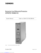
Siemens Siprotec 7SD600 System Manual (174 pages)
Numerical Line Differential Protection
Brand:
Siemens
| Category:
Protection Device
| Size: 1.84 MB
Advertisement
Related Products
Siemens SIPROTEC 7SD80
Siemens SIPROTEC 7ST622
Siemens SIPROTEC 7ST63
Siemens SIPROTEC 7SS60
Siemens Reyrolle 7SR54
Siemens 7SR51
Siemens SIPROTEC 7SJ531
Siemens SIPROTEC easy 7SJ45
Siemens 7SG23 MSCDN - MP2A
Siemens SIPROTEC 7ST61
Siemens Categories
Industrial Equipment
Controller
Control Unit
Oven
Washer
More Siemens Manuals
Login
Sign In
OR
Sign in with Facebook
Sign in with Google
Upload manual
Upload from disk
Upload from URL