Sign In
Upload
Manuals
Brands
Pontiac Manuals
Automobile
Firebird
Pontiac Firebird Manuals
Manuals and User Guides for Pontiac Firebird. We have
3
Pontiac Firebird manuals available for free PDF download: Service Manual, Owner's Manual
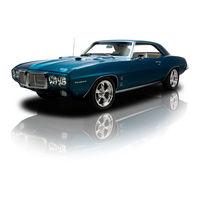
Pontiac Firebird Service Manual (849 pages)
1969
Brand:
Pontiac
| Category:
Automobile
| Size: 42.45 MB
Table of Contents
Table of Contents
2
General Information
3
Vehicle Identification Plate
3
Body Identification Plate
3
Car Model Identification
3
Engine Identification
4
Transmission Serial Number
4
8-Cyl.
4
Turbo Hydra-Matic
4
Lifting and Towing
5
Two-Speed Automatic
5
Towing Precautions
6
Ignition Lock Assembly - Remove
6
Two-Speed Automatic Transmission Serial Number
6
Depressing Lock Cylinder Retainer Pin
6
Coding Side Bar Lock
7
Key Blanks
7
Exploded View of Ignition Lock Assembly
7
Key Coding Diagram
7
Basic Dimensions
8
Rocker Panel Heights
8
Ignition Lock Assembly
10
Lubrication
10
Manifold Heat Control Valve
10
Station Wagon Tailgate Hinge and Linkage
10
Drill Sizes
11
Decimal Equivalents
11
Weights and Measures
12
Hood Latch
12
Hood Hinges
12
Accelerator Linkage
12
Carburetor Fuel Filter
14
Air Cleaner Element
14
Automatic Transmission
14
Cooling System
14
Battery
15
Starting Motor
15
Alternator
15
Speedometer Cable
15
Heating and Ventilation Service
16
Temperature Cable Adjust
16
Air Control Cablgadjust
16
PONTIAC, TEMPEST and Flreblrd
16
Pontiac-Heater Cable and Wire Routing
17
Blower Speed Switch
18
Grand Prix-Heater Cable and Vacuum Hose Routing
18
Tempest and Firebird
19
Blower Motor Resistor
19
Heater Wiring Harness
19
Tempest-Heater Cable Routing
19
Air Control or Defroster Cable
20
Temperature Control Cable
20
Tempest and Firebird-Remove and Replace
20
Defroster Diaphragm and Hose
21
Air Diaphragm and Hose
21
Vacuum Supply Hose
21
Blower Motor; Impeller and or Inlet Duct
21
Grand Prix-Remove and Replace
22
Heater Core And/Or Case
22
Blower Motor and Air Inlet Duct Installation
23
Heater Hose Inlet and Outlet
24
Defroster Duct
24
Heater Wiring Schematic
24
Kick Pad Ventilators
25
Upper Level Ventilation
25
Heater Wiring Schematic-All
25
Pontiac-Upper Ventilation System
26
Tempest and Grand Prix-Upper Ventilation System
26
Firebird Upper Ventilation System
26
Power Flow Ventilation System
27
Vent Motor
27
Typical-Power Flow Vent Motor and Duct
27
Power Flow Ventilation Wire Harness Typical
27
Custom Air Conditioner
28
Component Replacement and Adjustment
28
Precautionary Service Measures
28
Refrigeration Sub-Assemblies
28
Table of Contents
28
Caution--Liquid Indicator
29
Depressurizing the System-All
29
Evacuating the System
29
Preparati~Ns for Evacuating Complete System
29
Evacuating Complete System
30
Charging the System
31
Refrigerant Drum Method
31
Refrigerant-12 Disposable Can Method
32
Schematic - Charging Refrigeration System
32
Service Station Method
33
Filling Charging Cylinder
33
Charging the System Using J 8393
33
Adding Refrigerant 1A-7
34
Checking Compressor Oil Level and Adding Oil
35
Replacing Refrigeration System
35
Components Other than Compressor
35
Removing and Installing Compressor
36
Installing Compressor
36
Compressor Hub and Drive Plate Assembly
37
Compressor Replacement
37
Removing Hub and Drive Plate Lock Nut
38
Removing Hub Retainer Ring and Spacer
38
Removing Hub Retainer and Spacer
38
Compressor Pulley Anwor Bearing Assembly
39
Proper Position of Hub and Drive Key
39
Removing Pulley and Bearing Assembly Retainer Ring
39
Installing Hub and Drive Plate Assembly
39
Compressor Clutch Coil and Housing Assembly
40
Removing Pulley Bearing Retainer Ring
40
Installing Pulley Bearing
40
Remove Compressor Assembly to Service Engine-Pontiac and Tempest
41
Compressor Shaft Seal Assembly
41
Removing Coil Housing Retainer Ring
41
Removing Shaft Seal Seat
42
Removing Shaft Seal Seat Retainer
42
Removing Shaft Seal Assembly
42
Compressor Assembly-Overhaul
43
Preservation and Packing Service Parts
43
Removing O-Ring Seal
43
Major Interior Mechanism
43
Overhaul Compressor
44
Compressor Rear Head Assembly
44
Compressor Major Interior Mechanism
44
Sealing Surface on Head Casting Web
44
Removing Suction Reed
45
Removing Oil Inlet Tube
45
Pistons and Cylinder
45
Separating Cylinder Halves
46
Compressor Parts in Tray
46
Identification of Front End of Piston
46
Removing Rear Thrust Races and Bearings
47
Exploded View Compressor Assembly
48
Mainshaft Thrust Bearing Installed
49
Installing Piston with Balls
49
Zero Shoe and Ball at Front of Piston
49
Installing Rear Cylinder Half on Front Cylinder Half
49
Internal Mechanism in Fixture
50
Measurements and Table of Available Service Shoes and Thrust Races
50
Measuring for Proper Shoe
50
Checking Compressor Mainshaft End Play
50
Assemble with New Parts
51
Measuring for Proper Thrust Race
51
Installing Service Discharge Crossover
51
Installing Service Discharge Crossover Parts
51
Installing Front Head Casing
52
Identification O F Front and Rear Discharge Valve Plate
52
Installing Service Discharge Crossover Tube
52
Installing Oil Intake (Pick-Up) Tube
53
Positioning Oil Pump Outer Gear
53
P.o.a. Valve
54
Seating Seal Seat Retainer
54
Installing Rear Head
54
Refrigeration System Typical Tempest and Grand Prix
55
Expansion Valve and Seals
56
Evaporator Core
57
Evaporator Case Left Half
57
Condenser and Seals
58
Receiver Dehydrator
58
Air Inlet and Valve Assembly 1A-31
58
Blower Motor Impeller Andor Blower Motor Case
59
Air Inlet Assembly Typical Pontiac, Tempest and Grand Prix
59
Heater Core and Case Assembly
60
Air Inlet and Plenum Air Valve
60
Temperature Cable
61
Hi Blower Relay; Resistor Block; and Ambient Switch
61
Heater Core and Case Installation
61
Control Panel .1A-34
61
N C Engine Compartment and Jumper Harnesses
64
Diverter Door Diaphragms
64
Defroster Diaphragm
64
Air Inlet Diaphragms
65
Plenum Air Valve Diaphragm .1A-38
65
Cold Air Distribution: Center Air Outlet; and Side Outlet Ducts
66
Tempest Control Panel Details
66
Pontiac Control Panel Detaik
66
Vacuum Hose Harness
67
In-Car A/C Wiring Harness
67
Air Conditioning Wiring Schematic
69
Compressor Mounting and Belt a D J ~ S T ~ E N T
69
A/C in Car Harness Routing and Connections
72
Adjust
74
Typical Pontiac and Grand Prix Vacu~Irn Schematic
76
Tempest Vacuum Schematic
76
Firebird Vacuum Schematic
77
Automatic Temperature Control
78
In-Car Sensor
78
Ambient Sensor and Switch
79
Vacuum Hose Harness
79
Control Panel Components
80
Temperature Control Switch
80
Variable Resistor
80
Grand Prix Vacuum Hose Installation
81
Pontiac Vacuum Hose Installation
81
Temperature Door Link to Programmer
83
Grand Prix Control Panel
83
Programmer
84
Using Tool J 23187 to Adjust Variable Resistor
84
Programmer Link Assembly
84
Amplifier-Remove and Replace
85
Programmer Wheel
85
Gear Inspection
85
Temperature Door Adjustment
85
Motor
86
Programmer Amplifier
86
Power Resistor
87
Bi Level Boost Switch
87
Vacuum Schematic
88
Wiring Schematic
88
Frame and Body Mountings
90
Pontiac and Tempest
90
Lifting Pontiac Cars with Hoists
90
Pontiac
91
Tempest
91
Frame Alignment
91
Body to Frame Mountings
92
Flreblrd
92
Underbody Alignment
92
Flreblrd BODY VIBRATION DAMPERS
92
Pontiac Body Bolts and Frame Gage Line Dimensions
93
Tempest and Grand Prix Body Bolts and Frame Gage Line Dimensions
94
Firebird Checking Dimensions, Lift Points and Body Bolt Locations
95
Specifications
96
Horizontal Dimensions
96
Vertical Dimensions
96
Side Rail at Spring Rear Shackle Hole
97
Firebird Convertible Floor Pan Reinforcement
97
Firebird Body Damper Locations
97
Front Suspension
98
Front Wheel Bearings
98
Check Adjustment
98
Suspension Alignment
99
Inspection before Checking Front Wheel Alignment
99
Cross Section of Steering Knuckle, Hub and Disc Assembly
99
Adjust Caster and Camber
100
Wheel Bearing Adjustment
100
Checking and Adjusting Sequence-Front Wheel Alignment
100
Checking Wheel Bearing Adjustment
100
Check and Set Toe-In
101
Measuring by Trammel
101
Removing Pontiac Upper Control Arm Nuts
101
Caster-Camber Shims (Tempest Shown)
101
Minor Services
102
Set Toe-In
102
Check Steering Axis Inclination
102
Check Toe-Out on Turns
102
Shock Absorber
103
Typical Shock Absorber Installation
103
Stabilizer Shaft
104
Major Services
104
Spring
104
Stabilizer Link Installation Except Firebird
104
Steering Knuckle
105
Stabilizer Shaft Installation
105
Upper Control Arm
106
Removing Coil Spring with J 23028
106
Coil Spring Position in Lower Control Arm
106
Upper Control Arm Shaft And/Or Bushings
107
Upper Control Arm Shaft Anwor Bushings
108
Lower Control Arm
109
Lower Control Arm Bushing
109
Upper Ball Joint
111
Lower Control Arm Rear Bushing Firebird
111
Lower Ball Joint
112
Lower Ball Joint Installation Except Pontiac
113
Torque Specifications
115
Front Wheel Alignment Specifications
115
Rear Suspension
116
Shock Absorber--Except Firebird
116
Shock Absorber-Firebird
117
Spring and Shock Absorber Anchor Plate
117
Rear Shock Absorber Installation
117
Rear Spring
118
Leaf Spring and Spring Eye Bushing
118
Removing Spring Front Bushing
119
Installing Spring Front Bushing
119
Main Leaf of Leaf Spring-Firebird
120
Upper Control Arm Bushing
120
Pontiac and Grand Prix Automatic Level Control System
122
Compressor, Reservoir and Regulator Valve Assembly
123
Disassembly of Compressor into Major Components
123
Disassembly of Piston--Diaphragm Assembly
123
Disassembly of First Stage Housing and Valve Mechanism
123
Disassembly of Second Stage Housing
124
Cleaning and Inspection of Parts
124
Piston and Diaphragm Assembly
124
First Stage Housing and Valve Mechanism
124
Second Stage Housing
125
Assembly of Second Stage Housing
125
Assembly of First Stage Housing and Valve Mechanism
125
Assembly of Piston--Diaphragm Assembly
126
Assembly of Major Components
126
Instructions for Fastening Tubing
126
Pontiac Automatic Level Control System
127
Grandprix Automatic Level Control System
128
Exploded View of Compressor
129
Removing Diaphragm Retainer
129
Distributor Valve Assembly
129
Trouble Diagnosis Tests
130
Removing Rocker Arm Pin
130
Installing Valve Tension Spring in Boss
130
Installing Check Valve
130
Parts Required
131
Compressor Output Test-On Car
131
Installing Distributor Arm
131
Installing Diaphragm Retainer
131
Height Control Valve Test-On Car Exhaust (Superlifts Inflated)
132
Time Delay Check
132
Installing Piston Seal
132
Filling System through Service Valve
132
Height Control Valve Test-Off Car
133
Test Gage Installed on Regulator Valve
133
Lines and Fittings
134
Superlift - Leak Test
134
Standard Differential
136
Axle Ratios
136
New Car Pre-Delivery Inspection
137
Periodic Service
137
Shock Absorbers
137
Cross Section O F Typical Rear Axle and Differential
137
Exploded V~Ew of Typical Differential Assembly
138
Minor Service and Repairs
143
Companion Flange
143
Checking Pinion Bearing Preload
143
Removing Drive Pinion Nut
143
Pinion Bearing Oil Seal
144
Remove Axle Shaft Assemblies
144
Axle Shaft Bearing
145
Removing Axle Shaft Bearing (Typical)
145
Installing Axle Shaft Bearing (Typical)
145
Replace Axle Shaft Assemblies
145
Major Repairs
146
Rear Axle Assembly
146
Removing Axle Shaft Seal
146
Pre-Repair Investigation
147
Gear Tooth Nomenclature
147
Red Lead Test
147
Effects of Increasing Load on Tooth Contact Pattern
148
Differential Cranking Tool
148
Desired Tooth Contact under Light Load
148
Adjustments Affecting Tooth Contact
148
Effects of Backlash on Tooth Pattern
149
Effects of Pinion Position on Tooth Pattern
149
Overhaul Differential
149
Differential Case
149
Effect on Pattern
150
Removing Difterential Case
150
Clean and Inspect
151
Removing Differential Side Bearing
151
Alignment Marks
151
Grand Prix Medium Duty
152
Removing Pinion Shaft
152
Installing Pinion Shaft Lucking Bolt
152
Install Differential Case Side Bearings
153
Remove Pinion Assembly
153
Disassemble Pinion Assembly
153
Replace Pinion Bearing Outer Races
154
Torquing Case Half Bolts
154
Installing Right Differential Side Bearing
154
Installing Left Differential Side Bearing
154
Setting Pinion Depth
155
Removing Companion Flange
155
Removing Rear Pinion Bearing
155
Installing Rear Pinion Bearing Outer Race
155
Securing Gauge Plate in Carrier
156
Installing Front Pinion Bearing Outer Race
156
Replace Pinion Assembly and Adjust Pinion Preload
157
Gauge Plate Installed
157
Checking Pinion Depth
157
Replace Differential Case and Adjust Side Bearing Preload
158
Pinion Shim
158
Installing Two Service Shims
159
Installing Service Spacer
159
Inserting Feeler Gauge
159
Adjusting Differential Backlash
160
Tapping Final Shim into Place
160
Checking Ring Gear to Pinion Backlash
160
Oil Leaks
161
Safe-T-Track Differential
163
Grand Prix
164
Cleaning and Inspection of Case
167
Differential Case Assemble
168
Installing Differential Side Bearing
168
Compressing Preload Springs
168
Checking Pinion Gear to Side Gear Clearance
168
Tempest, Firebird and Grand Prix
169
Propeller Shaft
174
Alignment of Engine and Propeller Shaft
174
Remove Propeller Shaft
174
Disassemble Universal Joints
174
Assemble Universal Joints
175
Pressing out Bearing
175
Tapping out Bearing
175
Supporting Splined Yoke
175
Install Propeller Shaft Assembly
176
Installing Journal to Yoke
176
Installing Snap Ring Retainer
176
Propeller Shaft Comparison and Usage Information
177
Standard Brakes
178
Service Operations
178
Brake Pedal
178
Pontiac Manual Brake System
178
Pedal Height
179
Brake Warning Light Checking Procedure
179
Tempest and Grand Prix Manual Brake System
179
Stop Light Switch
180
Brake Assembly Mechanism and Drums
180
Firebird Manual Brake System
180
Adjustment
180
Fluid Levels and Master Cylinder Details
181
Preparing to Back off Adjusting Screw
182
Backing off Adjusting Screw
182
Disassembly
182
Inspection &D Cleaning
182
Gauging Shoe to Drum Clearance
183
Typical Self Adjusting Brake Assembly Exploded View
183
Pontiac Parking Brake System
184
Tempest and Grand Prix Parking Brake System
185
Assembly
185
Prix, and Firebird
186
Firebird Parking Brake System
186
Hydraulic System
187
Master Cylinder
187
Wheel Cylinder
189
Master Cylinder Usage Chart
189
Bleeding Brakes
190
Wheel Cylinder
190
Parking Brake
191
Inspection, Cleaning and Lubrication
191
Flushing Hydraulic System
191
Parking Brake Pedal Removal
192
Parking Brake Pedal Installation
192
Front Cable Installation
192
Center Cable Removal and Installation
192
Pontiac Specifications
193
Pontiac Torque Specifications
193
Tempest, Grand Prix and Firebird Specifications
194
Tempest, Grand Prix and Firebird Torque Specifications
194
Delco-Moraine Power Brake
195
Checks and Adjustments on Car
195
Pontiac Power Brake System
195
Special Tools
195
Stop Lamp Switch
196
Front Housing
196
Power Piston
196
Firebird Power Brake System
197
Power Brake
198
Air Filter
198
Exploded View of Pontiac Power Brake Unit
199
Power Piston - Install
200
Removing Locking Ring from Power Piston
202
Removing Reaction Retainer
202
Removing Support Plate
203
Removing Air Valve
203
Exploded View of Master Cylinder
203
Installing Front Housing
204
Push Rod Adjustment
204
Bendix Power Brake
205
Overhaul Bendix Power Brake
206
Valve Plunger Stop Key
207
Inspect Hydraulic Master Cylinder Assembly
208
Inspect Air Filters
208
Power Unit and Master Cylinder
208
Master Cylinder-Exploded View
208
Installing Rear Vacuum Seal
209
Power Piston Assemble
209
Power Unit Assemble
209
Gauging Push Rod Length
209
Power Brake Assembly
210
Heavy Duty Power Brakes
212
Bendix Tandem Diaphragm Type
212
Master Cylinder and External Parts
212
Valve Rod, Retainers, Filter and Poppet
212
Power Section Disassembly
213
Power Unit - Exploded View
213
Removal of Rear Shell Vacuum Seal
214
Diaphragms, Plates, Retainer and Plunger
214
Valve Rod, Retainers, Filters and Poppet
214
Power Unit Special Tool Combination
214
Disassembly of Master Cylinder
215
Assembly of Master Cylinder
215
Power Unit Mounted in Press
215
Removing Center Plate from Rear Shell
215
Assembly of Vacuum Seal in Rear Shell
216
Assembly of Plates Plunger and Diaphragm
216
Assembly of Diaphragms and Plates in Front and Rear Shells
217
Installing Rear Shell Vacuum Seal
217
Master Cylinder Exploded View
217
Assembly of Reaction Disc, Push Rod and Vacuum Check Valve Grommet
218
Assembly of Valve Rod, Air Filter, Retainer and Poppet Parts
218
Gaging Push Rod Length
218
Push Rod Gage
218
Assembly of Push Rod Boot and Master Cylinder to Power Unit
219
Power Cylinder Exploded View
220
Over-All Brake Unit
221
Separating Front and Rear Shells
221
Power Piston Disassemble
222
Power Piston Exploded View
222
Preparing to Separate Primary and Secondary Pistons
223
Preparing to Remove Primary Support Plate
223
Removing Primary Power Piston
223
Removing Air Valve-Pushrod Assembly
223
Master Cylinder Disassemble
224
Installing Control Valve and Retainer
225
Gaging Reaction Piston
225
Installing Snap Ring on Air Valve
225
Installing Housing Divider
226
Securing Front Housing to Arbor Press
227
Securing Rear Housing to Tools
227
Joining Front and Rear Housings
228
Gaging Master Cylinder Piston
228
Power Cylinder Only
229
Master Cylinder Only
229
Disc Brakes
231
Lining Inspection
231
Shoe and Lining Replacement
231
Caliper
231
Disc Brake Assembly
232
New and Worn Linings
233
Removing Mounting Bolts
233
Exploded View of Caliper
234
Boot Installation
234
Inserting Shoe Support Spring
235
Installing Outboard Shoe
235
Installing Inboard Shoe
235
Clinching Outboard Shoe
235
Bleeding Disc Brakes
236
Brake Rotor
236
Installing Mounting Bolts
236
Removing Piston
236
Surface Tolerance and Finish
237
Rotor Service
237
Lateral Runout Check
237
Parallelism Check
237
Checking Rotor for Lateral Runouf
238
Engine Mechanical
240
Six Cylinder Engine
240
Tempest and Firebird Engines
240
Pontiac and G. P. Engine Chart
240
Tempest Engine Chart
241
Firebird Engine Chart
241
Pontiac and Grand Prix Engines
242
Engine Number and Code Location
242
Vehicle Identification Number Location
242
Six-Cylinder Engine
243
Service Operations on Car
243
Engine Insulators
243
Valve Timing Marks
244
Drive Belts-Adjust (Except Timing Belt)
245
Intake and Exhaust Manifold or Gaskets
245
Cyl. Engine Mounting-Tempest
246
Timing Belt Adjustment Procedure
247
Timing Belt Adjustment
247
Cyl. Engine Mounting-Firebird
247
Accessory Drive Hosuing Mounting Bolts
247
Timing Belt Top Front Cover
247
Camshaft Sprocket or Seal
248
Adjusting Timing Belt Tension
248
Replace
248
Rocker Arm Cover Assembly and Gasket
249
Camshaft, Rocker Arm Cover Anwor Rocker Arm Cover Core Plug
249
Removing Camshaft Seal
249
Installing Camshaft Seal
249
Removing Camshaft from Cover
250
Thrust Washer Installation
250
Installing Camshaft Rear Plug
250
Rocker Arm or Hydraulic Valve Lash Adjuster
251
Lash Adjuster-Disassemble
251
Rocker Arm and Lash Adjuster
251
Hydraulic Lash Adjuster Recondition
251
Lash Adjuster-Clean and Inspect
252
Lash Adjuster-Assemble
252
Lash Adjuster-Exploded View
252
Lash Adjuster Test Leak-Down Rate
253
Valve Springs, Shield or Seal
253
Lash Adjuster-Wash Tank and Tray
253
Testing Leak down Rate
253
Cylinder Head or Gasket
254
Valve Spring Removal Hook-Up
254
Valve Spring Removal
254
Replace
254
Cylinder Head and Valves
255
Intake Valve Guide Seal Installation
255
Cylinder Head Locating Dowel Pins
255
Fitting Valve Stems to Guides
256
Valves and Seats Recondition
256
Cleaning Valve Guide Bore
256
Reaming Valve Guide Bore
256
Harmonic Balancer
257
Valve Seat and Face Angle
257
Lower Front Timing Cover Retaining Bolts
257
Lower Front Timing Belt Cover
258
Front Crankcase Cover and Gasket-Remove and Replace
258
Removing Crankshaft Front Seal
258
Crankshaft Timing Belt Sprocket or
258
Oil Pump
259
Housing Assembly
259
Pressure Regulator Valve-Oil Pump
259
Remove and Replace
259
Oil Filter By-Pass Valve
260
Accessory Drive Housing-Exploded View
260
Oil Pump Gears
260
Remove and Replace
260
Oil Pan
261
Housing Mounting Bolts
261
Oil Filter Bypass Valve
261
Removing Eccentric and Distributor Drive Gear Pin
262
Installing Bearing
262
Removing Bearing and Seal
262
Installing Seal
262
Replace
262
Main Bearings-Remove and Replace
263
Removing Rear Main Bearing Cap
263
Rear Main Bearing Cap Side
263
Connecting Rod Bearings-Remove and Replace
264
Removing Upper Rear Main Oil Seal
264
Tool for Removing Upper Half of Main Bearing
264
Plastigage (or Equivalent) in Place
265
Measuring Plastigage (or Equivalent)
265
Cylinder Bores-Inspect
266
Checking Connecting Rod Side Clearance
266
Cylinder Ring Ridge
266
Checking Crankshaft End Play
266
Honing or Boring
267
Removing Piston Pin-Step
267
Checking Piston Pin Fit
267
Measuring out O F Round Taper
267
Normal Cylinder Wear Pattern
268
Piston Sizing Points
268
Measuring Cylinder Gauge
268
Piston Fit and Replace
268
Connecting Rod to Piston - Assemble
269
Piston Pin Replacement
269
Piston and Rod Assembly
269
Piston Rings - Install
270
Checking Ring Side Clearance
270
Checking Ring Gap
270
Fitted Block Assembly
271
Connecting Rod Guide Tool
271
Installing Piston in Cylinder
271
Crankshaft
271
Replace
271
6 Cylinder Engine Wrench Torque Specifications
272
6 Cylinder Engine Specifications
273
Horsepower and Torque
273
Cylinder Special Engine Tools
276
V-8 Engine - Service
277
Cylinder Block
277
Cylinder Head
277
Camshaft and Drive
278
Pistons and Connecting Rods
278
Valve Train
278
Combustion Chamber
278
Rear Insulator
280
Engine Insulators Tempest
280
Pontiac Engine Insulators
280
Drive Belts
282
Engine Assembly
282
Tempest Engine Insulators
282
Firebird Engine Insulators
282
Right Side Exhaust Manifold or Gasket
283
Intake Manifold or Gasket
284
Left Side Exhaust Manifold or Gasket
284
Intake Manifold Gasket Retainers
284
Push Rod Cover or Gasket
285
Push Rod or Valve Lifter
286
Checking Valve Stem Seal
286
Lifter Wash Tank and Tray
286
Removing Push Rod Seat Retainer
286
Valve Lifter-Recondition
287
Valve Lifter - Clean and Inspect
287
Valve Lifter
287
Valve Lifter Assemble
288
Test Valve Lifter Leak-Down Rate
288
Hydraulic Valve Lifter
289
Testing Leak-Down Rate
289
Rocker Arm Studs
290
Rocker Arm Stud Removal
290
Slots Filed in Rocker Arm Stud
290
Installing Rocker Arm Stud
291
Cleaning Valve Guide
291
Reaming Valve Guide
292
Valve Seat and Face Angles
292
Valve Seat after Grinding with Flat Stone
292
Timing Chain Cover Seal
294
Front of Engine with Timing Chain Cover Removed
294
Aligning Timing Marks
294
Camshaft And/Or Camshaft Bearing
295
Timing Chain and Sprockets
295
Positioning Index Collar
296
Removing Camshaft Bearing
296
Installing Camshaft Bearing
297
Oil Pan Anvor Oil Pan Gasket Pontiac and Firebird Models
298
Oil Pan Gasket Retainers
298
Front Oil Pan Gasket Overlapping Side Gaskets
298
Rear Oil Pan Gasket Positioned in Bearing Cap
298
Oil Pump and Oil Pump Drive Shaft
299
Oil Pan And/Or Oil Pan Gaskets
300
Rear Main Bearing Oil Seal
300
Rear Main Bearing Seal Tool
301
Forming New Seal in Cap
301
Engine Oil Pan Baffle and Dipstick Tube
301
Measuring Plastigage
302
Connecting Rod Bolt Guide Set Installed
303
Installing Piston Assembly
303
Connecting Rod and Piston Assembly
304
Measuring Cylinder Bore
305
Fit and Replace Piston
306
Assemble Connecting Rod to Piston
307
Replace Piston Pin
307
Fitting Pin in Piston
307
Piston Rings
308
Installing Piston Pin
308
Crankshaft
309
Measuring Crankshaft End Play
309
Drain Holes in Lifter Gallery
310
Cylinder Block - View from Left Front
311
Hydraulic Lifter Equipment
314
Engine Wrench Torque Specifications
316
Engine Specifications
316
V-8 Special Engine Tools
321
Engine Cooling and Lubrication
322
Radiator
322
Radiator Cap
322
Water Plimp-6 Cylinder
323
Flushing Cooling System
323
Preparing Cooling System for Coolant
323
Checking and Filling Cooling System
323
Inhibitors
324
Testing Coolant
324
Thermostat Remove and Replace
324
Water Pump-6 Cylinder
324
Radiator Support and Baffle Assembly
325
Engine Oil
326
6 Cyl and 8 Cyl Remove and Replace
326
Fan Types and Usage
330
Radiator Usage
331
Firebird
331
Engine Fuel
332
Carburetor Air Cleaner and Silencer
332
Heat Riser Valve
332
Intake Systems
332
Air Cleaner Installation
333
Air Cleaner and Seal Installation
333
Baffle and Hood Scoop Installation GTO
334
Air Cleaner & Seal Installation Firebird
334
Baffle & Hood Scoop Installation Firebird
335
Ram Air Intake Schematic
335
Idle Stop Solenoid
336
Accelerator Controls
337
TEMPEST, GRAND Prlx and FIREBIRD
337
Vapor Diverter
337
Air Horn Removal
338
Air Horn Disassembly
338
Rochester MV Carburetor
338
Float Bowl Disassembly
339
Throttle Body Removal and Disassembly
339
Float Bowl Assembly
340
Throttle Body Disassembly
340
Carburetor Assembly and Adjustment Procedures
340
Throltle BODY ASSEMBLY and INSTALLATION
340
Metering Rod Adjustment
341
Float Level Adjustment
341
Air Horn Assembly and Installation
342
Fast Idle Adjustment (on Car)
342
Idle Vent Adjustment
342
Advertisement
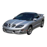
Pontiac Firebird Owner's Manual (407 pages)
Brand:
Pontiac
| Category:
Automobile
| Size: 19.11 MB
Table of Contents
For Canadian Owners Who Prefer a French Language Manual
3
How to Use this Manual
4
Safety Warnings and Symbols
4
Vehicle Damage Warnings
5
Section 1 Seats and Restraint Systems
8
Seats and Seat Controls
9
Manual Front Seat
9
Reclining Front Seatbacks
12
Head Restraints
14
Folding Rear Seatback
15
Safety Belts: They're for Everyone
15
Why Safety Belts Work
17
About Safety Belts and the Answers
20
Driver Position
21
Lap-Shoulder Belt
21
Safety Belt Use During Pregnancy
28
Right Front Passenger Position
29
Supplemental Restraint System (SRS)
29
How the Air Bag System Works
31
Servicing Your Air Bag-Equipped Vehicle
34
Rear Seat Passengers
35
Smaller Children and Babies
38
Child Restraints
41
Where to Put the Restraint
45
Top Strap
46
Securing a Child Restraint in a Rear Seat Position
47
Securing a Child Restraint in the Right Front Seat Position
49
Larger Children
51
Safety Belt Extender
54
Checking Your Restraint Systems
54
Replacing Restraint System Parts after a Crash
54
Section 2 Features and Controls
56
Door Locks
59
Power Door Locks - if Equipped
60
Leaving Your Vehicle
61
Remote Keyless Entry System
61
Operation
63
Matching Transmitter(S) to Your Vehicle
64
Battery Replacement
65
Hatch Release
66
Key in the Ignition
68
Parking at Night
68
Parking Lots
68
Content Theft-Deterrent System (if Equipped)
69
Shock Sensor
69
Arming the System
70
Disarming the System
71
Feature Customization (if Equipped)
73
Leaving Programming Mode
78
Ignition Positions
79
Key Release Button
80
Starting Your Engine
81
Engine Coolant Heater (Canada Only)
84
To Use the Engine Coolant Heater
84
Automatic Transmission Operation
85
Manual Transmission Operation
90
Shift Speeds
92
Shifting into PARK (P) :Automatic Transmission Only)
94
Torque Lock (Automatic Transmission)
95
Shifting out of PARK (P) (Automatic Transmission)
96
Parking Your Vehicle (Manual Transmission)
96
Parking over Things that Burn
97
Engine Exhaust
97
Running Your Engine While You're Parked (Automatic Transmission)
98
Limited-Slip Rear Axle
99
Parking Brake
99
Manual Windows
100
Power Windows - if Equipped
100
Tilt Steering Wheel
101
Turn Signavmultifunction Lever
101
Headlamp High/Low-Beam
102
Windshield Wipers
103
Windshield Washer
104
Cruise Control
104
Exterior Lamps
107
Headlamps on Reminder
107
Daytime Running Lamps
108
Fog Lamps
109
Interior Lamps
110
Front Map Lamps
111
Retained Accessory Power (RAP)
111
Storage Compartments
113
Ashtray and Lighter
115
Sun Visors
116
Visor Vanity Mirror
116
Accessory Plug
117
Floor Mats
117
Twin Lift-Off Roof Panels
117
Convertible Top
124
Installing the Boot Cover
126
Instrument Panel
131
Instrument Panel Cluster
133
Speedometer and Odometer
134
Warning Lights, Gages and Indicators
134
Safety Belt Reminder Light
135
Airbag Readiness Light
136
Brake System Warning Light
137
Anti-Lock Brake System Warning Light
138
Low Traction Light
139
Engine Coolant Temperature Gage
139
Oil Pressure Gage
143
Section 3 Comfort Controls and Audio Systems
146
Comfort Controls
147
Air Conditioning
148
Defogging and Defrosting
149
Rear Window Defogger (if Equipped)
150
Ventilation System
151
Audio Systems
152
Setting the Clock
152
AM-FM Stereo with Cassette Tape Player and Equalizer (if Equipped)
152
AM-FM Stereo with Compact Disc Player and Equalizer (if Equipped)
156
Monsoon AM-FM Stereo with Compact Disc Player and Equalizer (if Equipped)
157
Trunk Mounted CD Changer (if Equipped)
159
Theft-Deterrent Feature
162
Audio Steering Wheel Controls (if Equipped)
164
Understanding Radio Reception
165
Tips about Your Audio System
165
Care of Your Cassette Tape Player
166
Care of Your Compact Disc Player
167
Power Antenna Mast Care
167
Section 4 Your Driving and the Road
170
Defensive Driving
171
Drunken Driving
172
Control of a Vehicle
174
Anti-Lock Brakes (Abs)
176
Braking in Emergencies
179
Power Steering
179
Pontiac Firebird Owner's Manual (386 pages)
Brand:
Pontiac
| Category:
Automobile
| Size: 20.34 MB
Table of Contents
Table of Contents
2
How to Use this Manual
4
Seats and Restraint Systems
8
Comfort Controls and Audio Systems
134
Audio System
144
Your Driving and the Road
152
Problemsontheroad
190
Service and Appearance Care
234
Maintenance Schedule 11
344
Customer Assistance Information
362
Advertisement
Advertisement
Related Products
Pontiac firebird 98
Pontiac firebird 1968
Pontiac Firebird 1977
Pontiac FIREBIRD 1972
Pontiac Fiero 1988
Pontiac 1993 Bonneville SSE
Pontiac 1993 Bonneville SSEi
Pontiac 1952 Chieftain
Pontiac 1952 Sedan Delivery
Pontiac 1952 Station Wagon
Pontiac Categories
Automobile
Car Navigation system
Automobile Accessories
Car Video System
More Pontiac Manuals
Login
Sign In
OR
Sign in with Facebook
Sign in with Google
Upload manual
Upload from disk
Upload from URL