Sign In
Upload
Manuals
Brands
Philips Manuals
DVD VCR Combo
DVP3350V/01
Philips DVP3350V/01 Manuals
Manuals and User Guides for Philips DVP3350V/01. We have
2
Philips DVP3350V/01 manuals available for free PDF download: Service Manual
Philips DVP3350V/01 Service Manual (122 pages)
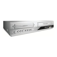
VCR+DVD PLAYER
Brand:
Philips
| Category:
DVD Player
| Size: 12.95 MB
Table of Contents
Section 1 Summary
3
Section 1 Summary
2
Table of Contents
3
Product Safety Servicing Guidelines for DVD+Vcr Products
4
Servicing Precautions
5
General Servicing Precautions
5
Insulation Checking Prodedure
5
Electrostatically Sensitive Devices
5
Information about Lead-Free Soldering
6
Service Information for Eeprom IC Setting(Vcr)
7
Service Information for Eeprom (DVD)
8
Specifications
9
Section 2 Cabinet & Main Chassis
10
Exploded Views
11
Cabinet and Main Frame Section
11
Deck Mechanism Section [ DVD MD (Dp-10C) ]
12
Deck Mechanism Section [ Vcr Deck D37(N) ]
13
Front Loading Mechanism Section
13
Moving Mechanism Section (1)
14
Moving Mechanism Section (2)
15
Packing Accessory Section
16
Section 3 Electrical
18
Vcr Part
19
Vcr Electrical Adjustment Procedures
19
Servo Adjustment
19
Vcr Electrical Troubleshooting Guide
20
Power(Smps) Circuit
20
System/Key Circuit
23
Servo Circuit
24
Y/C Circuit
27
Hi-Fi Circuit
31
Tuner/If Circuit
34
Block Diagrams
36
Power(Smps) Block Diagram
36
System Block Diagram
37
Avcp Block Diagram
38
Hi-Fi Block Diagram
39
Tuner Block Diagram
40
Circuit Diagrams
41
Power(Smps) Circuit Diagram
41
System Circuit Diagram
42
Avcp Circuit Diagram
43
Hi-Fi Circuit Diagram
44
Tuner Circuit Diagram
45
Waveforms
46
Circuit Voltage Chart
47
IC Block Diagrams
50
Printed Circuit Board Diagrams
52
Main P.C.board (Top Side)
52
Main P.C.board (Bottom Side)
53
Power P.C.board
54
Key P.C.board
55
DVD Part
56
DVD Electrical Troubleshooting Guide
56
Power Check Flow
56
System Operation Flow
57
Test & Debug Flow
58
Details and Waveforms on System Test and Debugging
64
System 27Mhz Clock, Reset Signal
64
Sdram Clock
65
Tray Open/Close Signal
65
Sled Control Related Signal (no Disc Condition)
67
Lens Control Related Signal (no Disc Condition)
67
Laser Power Control Related Signal (no Disc Condition)
68
Focus on Waveform
68
Spindle Control Waveform (no Disc Condition)
69
Tracking Control Related Signal (System Checking)
70
Rf Waveform
71
Zr36966 Audio Optical and Coaxial Output (Spdif)
71
Zr36966 Video Output Waveform
72
Audio Output from Audio Preamp
73
Block Diagrams
74
System Block Diagram
74
Servo Block Diagram
75
Audio & Video In/Out Block Diagram
76
Circuit Diagrams
78
Mpeg Circuit Diagram
78
Servo Circuit Diagram
79
Jack Circuit Diagram
80
IC Block Diagrams
81
Section 4 Mechanism of VCR Part(D-37)
82
Top View
83
Mechanism Parts Locations
83
Top View
83
Bottom View
83
Bottom View
84
Disassembly and Assembly of Deck Mechanism
84
Disassembly of Drum Assembly
84
Holder Assembly CST
86
Disassembly of Gear Assembly Rack F/L
86
Opener Door
86
Arm Assembly F/L
86
Lever Assembly S/W
86
Motor Assembly L/D
87
Gear Wheel
87
Arm Assembly Cleaner
87
Head F/E
87
Base Assembly A/C Head
87
Brake Assembly T
88
Arm Assembly Tension
88
Reel S / Reel T
88
Base Assembly P4
89
Opener Lid
89
Arm Assembly Pinch
89
Arm T/Up
89
Supporter, Capstan
90
Belt Capstan/Motor Capstan
90
Lever F/R
90
Clutch Assembly D37
90
Gear Drive/Gear Cam
91
Gear Sector
91
Brake Assembly Capstan
91
Plate Slider
91
Lever Tension
91
Lever Spring
91
Lever Brake
91
Gear Assembly P2/Gear Assembly P3
92
Base Assembly P2/Base Assembly P3
92
Base Loading
92
Base Tension
93
Arm Assembly Idler Jog
93
Deck Mechanism Adjustment
94
Fixtures and Tools for Service
94
Mechanism Assembly Mode Check
95
Previous Preparation for Deck Adjustment
96
Torque Measuring
96
Guide Roller Height Adjustment
97
Fine Adjustment
97
Prior Adjustment
97
Audio/Control (A/C) Head Adjustment
98
Prior Adjustment
98
Fine Adjustment (Azimuth Adjustment)
99
Tape Path Check between Pinch Roller and Take-Up Guide
99
X-Distance Adjustment
99
Adjustment after Drum Assembly (Video Heads)
100
Check of Traveling Device after Deck Assembly
100
Audio, RF Normalization Time (Locking Time) Check in Play after CUE or REV
100
Check of Tape Curl and Jam Status
100
Protection, Maintenance and Check of Video Function
101
Essential Check and Repair
102
Regular Check and Repair
102
Tools for Check and Repair
102
Maintenance Process
102
Removal of Foreign Materials
102
Grease Application
103
Troubleshooting Guide
105
Deck Mechanism
105
Front Loading Mechanism
108
Exploded Views
110
Front Loading Mechanism Section
110
Moving Mechanism Section(1)
111
Moving Mechanism Section(2)
112
Section 5 Mechanism (Dp-10C)
114
Deck Mechanism Parts Locations
115
Top View (with Tray)
115
Top View (Without Tray Disc)
115
Bottom View
115
Deck Mechanism Disassembly
116
Main Base
116
Clamp Assembly Disc
116
Clamp Upper
116
Magnet Clamp
116
Plate Clamp
116
Tray Disc
116
Base Assembly Sled
117
Gear Feed
117
Gear Middle
117
Gear Rack
117
Rubber Rear
117
Frame Assembly Up/Down
118
Belt Loading
118
Gear Pulley
118
Gear Loading
118
Guide Up/Down
118
Pwb Assembly Loading
118
Base Main
118
Exploded View
120
Deck Mechanism Exploded View
120
Advertisement
Philips DVP3350V/01 Service Manual (126 pages)
VCR+DVD PLAYER
Brand:
Philips
| Category:
DVD VCR Combo
| Size: 23.19 MB
Table of Contents
Section 1 Summary
3
Section 1 Summary
2
Section 3 Electrical
2
Table of Contents
3
Product Safety Servicing Guidelines for Vcr+DVD Products
4
Servicing Precautions
5
General Servicing Precautions
5
Insulation Checking Prodedure
5
Electrostatically Sensitive Devices
5
Information about Lead-Free Soldering
6
Service Information for Eeprom IC Setting(Vcr)
7
Service Information for Eeprom (DVD)
8
Specifications
9
Section 2 Cabinet & Main Chassis
10
Exploded Views
11
Cabinet and Main Frame Section
11
Deck Mechanism Section [ DVD MD (DP-10C) ]
12
DECK Mechanism Section [ VCR DECK D37(N) ]
13
Front Loading Mechanism Section
13
Moving Mechanism Section (1)
14
Moving Mechanism Section (2)
15
Packing Accessory Section
16
Section 3 Electrical
17
Electrical Section
17
Electrical Adjustment Procedures
18
Servo Adjustment
18
Vcr Part
18
Electrical Troubleshooting Guide
19
Power(Smps) Circuit
19
System/Key Circuit
22
Servo Circuit
23
Y/C Circuit
26
Hi-Fi Circuit
30
Tuner/If Circuit
33
DVD Part
58
Electrical Troubleshooting Guide
58
Power Check Flow
58
System Operation Flow
59
Test & Debug Flow
60
Waveforms
64
Details and Waveforms on System Test and Debugging
66
System 27Mhz Clock, Reset, Flash R/W Signal
66
Sdram Clock
67
Tray Open/Close Signal
67
Sled Control Related Signal(no Disc Condition)
69
Lens Control Related Signal(no Disc Condition)
69
Laser Power Control Related Signal(no Disc Condition)
70
Disc Type Judgement Waveform
70
Focus on Waveform
72
Spindle Control Waveform(no Disc Condition)
73
Tracking Control Related Signal(System Checking)
74
Zr36882 Audio Optical and Coaxial Output(Spdif)
75
Rf Waveform
75
Zr36882 Video Output Waveform
76
Audio Output from Audio Dac
77
Block Diagrams
79
System Block Diagram
79
Servo Block Diagram
80
Audio & Video In/Out Block Diagram
81
Troubleshooting Guide
86
Top View
87
Bottom View
87
Disassembly of Gear Assembly
90
Deck Mechanism Adjustment
98
Fixtures and Tools for Service
98
Mechanism Assembly Mode Check
99
Torque Measuring
100
Guide Roller Height Adjustment
101
Prior Adjustment
101
Fine Adjustment
101
Audio/Control (A/C) Head Adjustment
102
X-Distance Adjustment
103
Essential Check and Repair
106
Tools for Check and Repair
106
Maintenance Process
106
Regular Check and Repair
106
Plate Slider
107
Deck Mechanism
109
Front Loading Mechanism
112
Advertisement
Related Products
Philips DVP3355V
Philips DVP3350V
Philips DVP3350V/19
Philips DVP3350V/02
Philips DVP3345V/17
Philips DVP3345VB/F7
Philips DVP3345V/F7E
Philips DVP3340V
Philips DVP3340V/17
Philips DVP3340V/17B
Philips Categories
TV
Monitor
Stereo System
Electric Shaver
CD Player
More Philips Manuals
Login
Sign In
OR
Sign in with Facebook
Sign in with Google
Upload manual
Upload from disk
Upload from URL