Sign In
Upload
Manuals
Brands
Omron Manuals
Engine
OMNUC G Series
Omron OMNUC G Series Manuals
Manuals and User Guides for Omron OMNUC G Series. We have
2
Omron OMNUC G Series manuals available for free PDF download: User Manual
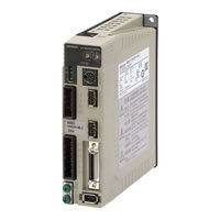
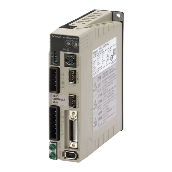
Omron OMNUC G Series User Manual (460 pages)
AC SERVOMOTORS/SERVO DRIVES WITH BUILT-IN MECHATROLINK-II COMMUNICATIONS
Brand:
Omron
| Category:
Servo Drives
| Size: 6.53 MB
Table of Contents
Items to Check When Unpacking
13
About this Manual
19
Table of Contents
20
Overview
24
Features
24
System Configuration
25
Names of Parts and Functions
26
Servo Drive Part Names
26
Servo Drive Functions
27
Forward and Reverse Motor Rotation
27
System Block Diagrams
28
Applicable Standards
33
EC Directives
33
UL and CSA Standards
33
Korean Radio Regulations (KC)
34
Semi F47
34
Chapter 2 Standard Models and Dimensions
35
Standard Models
36
External and Mounting Hole Dimensions
60
Servo Drive Specifications
110
Servo Drive Specifications
116
Main Circuit and Servomotor Connector Specifications
116
Control I/O Connector Specifications (CN1)
119
Control Input Circuits
123
Control Output Circuits
123
Control Sequence Timing
124
Encoder Connector Specifications (CN2)
125
Parameter Unit Connector Specifications (CN3)
125
Servomotor Specifications
126
General Specifications
126
Encoder Specifications
140
Decelerator Specifications
141
Standard Models and Specifications
141
Cable and Connector Specifications
154
Encoder Cable Specifications
154
Absolute Encoder Battery Cable Specifications
160
Servomotor Power Cable Specifications
161
Communications Cable Specifications
181
Connector Specifications
182
MECHATROLINK-II Communications Cable Specifications
185
Control Cable Specifications
187
Parameter Unit Specifications
192
External Regeneration Resistor Specifications
193
Reactor Specifications
195
MECHATROLINK-II Repeater Specifications
196
Installation Conditions
200
Servo Drives
200
Servomotors
202
Decelerators
206
Wiring
212
Connecting Cables
212
Selecting Connecting Cables
213
Peripheral Device Connection Examples
217
Main Circuit and Servomotor Connector Specifications
221
Wiring Conforming to EMC Directives
227
Wiring Method
227
Selecting Connection Components
232
Conformity to IEC 61800-5-1
245
Regenerative Energy Absorption
247
Calculating the Regenerative Energy
247
Servo Drive Regenerative Energy Absorption Capacity
250
Absorbing Regenerative Energy with an External Regeneration Resistor
251
Connecting an External Regeneration Resistor
252
Position Control
256
Position Control
257
Speed Control
259
Speed Control
260
Torque Control
262
Torque Control
264
Forward and Reverse Drive Prohibit
265
Brake Interlock
266
Torque Limit
271
Torque Limit
272
Soft Start
273
Acceleration/Deceleration Time Settings
274
Moving Average Time
275
Electronic Gear
276
Speed Limit
277
Sequence Input Signals
278
Sequence Output Signals
280
Backlash Compensation
282
Overrun Protection
284
Gain Switching
286
Speed Feed-Forward
293
Torque Feed-Forward
294
Speed Feedback Filter Selection
295
P Control Switching
296
Torque Command Filter Time Constant
297
Notch Filter
298
Adaptive Filter
300
Instantaneous Speed Observer
303
Damping Control
305
Damping Control
306
User Parameters
310
Setting and Checking Parameters
310
Parameter Tables
316
Details on Important Parameters
341
Operational Procedure
354
Preparing for Operation
355
Items to Check before Turning on the Power
355
Turning on Power
357
Checking the Displays
358
Absolute Encoder Setup
359
Using the Parameter Unit
361
Names of Parts and Functions
361
Setting the Mode
362
Changing the Mode
362
Monitor Mode
363
Parameter Setting Mode
370
Parameter Write Mode
376
Normal Mode Autotuning
377
Auxiliary Function Mode
378
Copy Mode
381
Trial Operation
384
Preparation for Trial Operation
384
Trial Operation with CX-Drive
384
Gain Adjustment
386
Purpose of the Gain Adjustment
386
Gain Adjustment Methods
386
Gain Adjustment Procedure
387
Realtime Autotuning
388
Realtime Autotuning Setting Method
389
Machine Rigidity Setting Method
389
Normal Mode Autotuning
394
Manual Tuning
399
Chapter 8 Troubleshooting
407
Error Processing
408
Alarm Table
410
Troubleshooting
414
Overload Characteristics (Electronic Thermal Function)
428
Periodic Maintenance
429
Chapter 9 Appendix
433
Parameter Tables
434
Advertisement
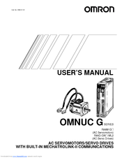
OMRON OMNUC G Series User Manual (438 pages)
AC SERVOMOTORS/SERVO DRIVES WITH BUILT-IN MECHATROLINK-II COMMUNICATIONS
Brand:
OMRON
| Category:
Engine
| Size: 24.36 MB
Table of Contents
Table of Contents
18
Items to Check When Unpacking
13
About this Manual
17
Table of Contents
18
Chapter 1 Features and System Configuration
22
Features
22
Overview
22
System Configuration
23
Names of Parts and Functions
24
Servo Drive Part Names
24
Servo Drive Functions
25
System Block Diagrams
26
Applicable Standards
31
EC Directives
31
UL and CSA Standards
31
Chapter 2 Standard Models and Dimensions
33
Standard Models
34
Servomotors
38
Standard Models
38
Decelerators
40
Accessories and Cables
47
External and Mounting Hole Dimensions
56
Servo Drives
56
Servomotors
66
Parameter Unit Dimensions
76
Servomotor and Decelerator Combinations
77
Decelerator Dimensions
80
External Regeneration Resistor Dimensions
94
Reactor Dimensions
95
Chapter 3 Specifications
99
Servo Drive Specifications
100
Servomotor Specifications
116
Decelerator Specifications
131
Cable and Connector Specifications
141
Parameter Unit Specifications
177
External Regeneration Resistor Specifications
178
Reactor Specifications
179
Chapter 4 System Design
181
Installation Conditions
182
Servo Drives
182
Servomotors
184
Decelerators
188
Wiring
192
Connecting Cables
192
Selecting Connecting Cables
193
Peripheral Device Connection Examples
197
Main Circuit and Servomotor Connector Specifications
201
Wiring Conforming to EMC Directives
207
Wiring Method
207
Selecting Connection Components
212
Regenerative Energy Absorption
225
Calculating the Regenerative Energy
225
Servo Drive Regenerative Energy Absorption Capacity
228
Absorbing Regenerative Energy with an External Regeneration Resistor
229
Connecting an External Regeneration Resistor
230
Chapter 5 Operating Functions
233
Position Control
234
Position Control
235
Speed Control
237
Speed Control
238
Torque Control
240
Torque Control
242
Forward and Reverse Drive Prohibit
243
Brake Interlock
244
Torque Limit
249
Torque Limit
250
Soft Start
251
Acceleration/Deceleration Time Settings
252
Moving Average Time
253
Electronic Gear
254
Speed Limit
255
Sequence Input Signals
256
Sequence Output Signals
258
Backlash Compensation
260
Overrun Protection
262
Gain Switching
264
Speed Feed-Forward
271
Torque Feed-Forward
272
Speed Feedback Filter Selection
273
P Control Switching
274
Torque Command Filter Time Constant
275
Notch Filter
276
Adaptive Filter
278
Instantaneous Speed Observer
281
Damping Control
283
Damping Control
284
User Parameters
288
Setting and Checking Parameters
288
Parameter Tables
294
Details on Important Parameters
319
Chapter 6 Operation
331
Operational Procedure
332
Preparing for Operation
333
Items to Check before Turning on the Power
333
Turning on Power
335
Checking the Displays
336
Absolute Encoder Setup
337
Using the Parameter Unit
339
Names of Parts and Functions
339
Setting the Mode
340
Changing the Mode
340
Monitor Mode
341
Parameter Setting Mode
348
Parameter Write Mode
354
Normal Mode Autotuning
355
Auxiliary Function Mode
356
Copy Mode
359
Trial Operation
362
Preparation for Trial Operation
362
Trial Operation with CX-Drive
362
Chapter 7 Adjustment Functions
363
Gain Adjustment
364
Purpose of the Gain Adjustment
364
Gain Adjustment Methods
365
Gain Adjustment Procedure
365
Realtime Autotuning
366
Realtime Autotuning Setting Method
367
Machine Rigidity Setting Method
367
7-2 Realtime Autotuning
370
Normal Mode Autotuning
372
Setting the Parameters
372
Manual Tuning
377
Basic Settings
377
Parameter no
380
Parameter Name
380
Pn010 Position Loop Gain
380
Pn011 Speed Loop Gain
380
Speed Loop Integration Time Constant
380
Constant
380
Torque Command Filter Time Constant *1
380
Pn018 Position Loop Gain
381
Setting
383
Chapter 8 Troubleshooting
385
Error Processing
386
Preliminary Checks When a Problem Occurs
386
Precautions When Troubleshooting
387
Replacing the Servomotor and Servo Drive
387
Alarm Table
388
Troubleshooting
392
Error Diagnosis Using the Displayed Alarm Codes
392
Error Diagnosis Using the Displayed Warning Codes
399
Overload Characteristics (Electronic Thermal Function)
405
Overload Characteristics Graphs
405
Periodic Maintenance
406
Servomotor Service Life
406
Servo Drive Service Life
407
Replacing the Absolute Encoder Battery
408
Chapter 9 Appendix
411
Parameter Tables
412
Advertisement
Related Products
OMRON OMNUC G
OMRON OMNUC G5
Omron OMNUC G5 Series
Omron OMNUC U Series
Omron OMNUC W Series
Omron OMNUC H Series
Omron OMNUC M Series
Omron OMNUC R Series
Omron OMNUC FND Series
Omron Omnus FND-X*-SRT Series
Omron Categories
Blood Pressure Monitor
Controller
Accessories
Switch
Inverter
More Omron Manuals
Login
Sign In
OR
Sign in with Facebook
Sign in with Google
Upload manual
Upload from disk
Upload from URL