Sign In
Upload
Manuals
Brands
Omron Manuals
Measuring Instruments
KE1-CTD8E
Omron KE1-CTD8E Manuals
Manuals and User Guides for Omron KE1-CTD8E. We have
1
Omron KE1-CTD8E manual available for free PDF download: User Manual
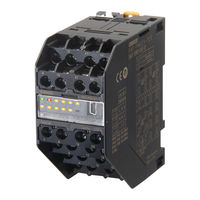
Omron KE1-CTD8E User Manual (106 pages)
Smart Power Monitor
Brand:
Omron
| Category:
Measuring Instruments
| Size: 3.87 MB
Table of Contents
Table of Contents
12
Introduction
2
Items on Which You Agree by Using this Product
3
Safety Precautions
5
Safety Points
7
Before Using this Product
9
Precautions for Use
9
Abbreviation
10
Relevant Manuals
10
Manual Revision History
11
Table of Contents
12
Chapter 1 Overview
15
Chapter 1. Overview
16
Main Functions
17
Function by Unit
17
Output Function
17
Input Function
19
Communication Function
19
Logging Function of Measurement Data
19
Name and Function of each Part
20
Name of each Part
20
Explanation of the Display Unit
21
Setting Switch
22
How to Use Setting Switches
22
System Configuration
23
Configuration
24
Multiple-Unit Connection
24
Minimum Configuration
25
Maximum Configuration
25
Multiple-System Configuration
26
Format Standard
27
Main Features and Functions
16
Main Features
16
Chapter 2. Preparation
28
Flow before Use
29
Setting Example
30
Setting List of Units
31
Installation
33
External Dimensions (Unit: MM)
33
Connection Method
34
Horizontally Connecting Hook
34
Connector
35
Installation Procedure
36
Installation of DIN Rail
36
Installation on a Wall
38
Installation of Dedicated CT
39
Wire Connection and Installation of Dedicated CT
40
Input/Output Configuration and Example of Wiring Diagram
41
Model KM1-PMU1A-FLK
41
Function of Terminal
41
Terminal Arrangements and Input/Output Configuration
41
Example of Wiring Diagram
42
Model KM1-PMU2A-FLK
43
Function of Terminal
43
Terminal Arrangements and Input/Output Configuration
43
Example of Wiring Diagram
44
Model KM1-EMU8A-FLK
46
Function of Terminal
46
Terminal Arrangements and Input/Output Configuration
46
Model KE1-CTD8E
47
Function of Terminal
47
Terminal Arrangements and Input/Output Configuration
47
Example of Wiring Diagram
48
Wiring
52
Requests for Wiring
52
Power Voltage
52
Input Voltage
53
USB Port
53
CT Input
54
Communication
55
Event Input
56
Output
56
Chapter 3 Functions
57
List of Functions
58
Basic Functions
59
Applicable Phase Wire
59
Synchronization Selection for Measuring Block
59
Dedicated CT Type
59
VT Ratio
60
CT Ratio
60
Low-Cut Function
60
Low-Cut Current Value
60
Average Count
61
Logging Function
61
Signal Detection
61
CT Signal Detection
61
Measurement Function
62
Active Power
62
Integrated Power Amount
62
Frequency
63
Power Factor
63
Reactive Power
63
Temperature Measurement
63
Voltage
63
Pulse Conversion Coefficient
64
Simple Measurement
64
Total Power Conversion Coefficient
64
Output Function
65
Ouptut Terminal 1/Output Terminal 2/Output Terminal 3 Function Setting
65
Integrated Power Amount Pulse Output
66
Pulse Output Unit
66
Reverse Phase
67
Alarm Output
68
Active Input Setting
68
Alarm History
68
Time Chart of Alarm Output Function
68
Active Power Alarm Output
69
Over Current Alarm Output
69
Under Current Alarm Output
69
Over Voltage Alarm Output
70
Power Factor Alarm Output
70
Under Voltage Alarm Output
70
Reactive Power Alarm Output
71
Reverse Phase Alarm Output
71
Temperature Alarm Output
71
Event Input Function
72
Event Input NPN/PNP Input Mode Setting
72
Event Input N-O/N-C Input Mode Setting
72
Function Using Event Input
73
Measurement Start Time/Measurement End Time
73
ON Time of Pulse Input
73
Power Original Unit
73
Pulse Input Count
73
3-STATE Function
74
3-STATE Target
74
3-STATE HIGH Threshold/3-STATE LOW Threshold
76
3-STATE Hysteresis
76
Other Functions
77
Time
77
Initialization
77
Chapter 4 Troubleshooting
78
Flow of Troubleshooting
79
Assume Based on Operation Indicator LED
79
Assume Based on Operation Indicator LED
80
Assume Based on the Status
81
Assume Based on Phenomena
82
Appendix
84
Product Specifications
85
Rating of Main Unit
85
Main Part Specifications
86
Protection Functions
88
Accessories
89
Connection Connector (Excepting Measurement Master
89
Dedicated CT
90
Specification
90
External Dimensions (Unit: MM
90
Split Type
90
Panel Fixed (Through) Type
91
Dedicated CT Cable
91
List of Parameters
92
List of Data Logging Items
98
Model KM1/KE1 Combination List
102
Advertisement
Advertisement
Related Products
Omron KE1-PGR1C-FLK
Omron KE1-PVS1C-FLK
Omron KE1-VSU1B-FLK
Omron KE1-VAU1B-FLK
Omron KE1-ZCT8E
Omron KE1-DRT-FLK
Omron KE1
Omron K3HB-XVD
Omron K6CM-CIM
Omron K6PM
Omron Categories
Blood Pressure Monitor
Controller
Accessories
Switch
Inverter
More Omron Manuals
Login
Sign In
OR
Sign in with Facebook
Sign in with Google
Upload manual
Upload from disk
Upload from URL