Omron FH-2 Series Manuals
Manuals and User Guides for Omron FH-2 Series. We have 8 Omron FH-2 Series manuals available for free PDF download: User Manual, Setup Manual, Hardware Setup Manual, Operation Manual, Instruction Sheet
Omron FH-2 Series User Manual (582 pages)
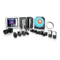
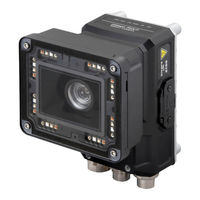
Vision Sensor
Brand: Omron
|
Category: Machine Vision Systems
|
Size: 26.64 MB
Table of Contents
-
-
-
-
All Series33
-
FH-L Series34
-
FHV Series35
-
-
Terminology
39 -
-
Features55
-
-
What Is a Scene
174 -
Creating a Scene
177 -
-
-
Setting Windows303
-
-
Windows
303 -
-
Judgement Pane324
-
Information Pane324
-
Toolbox Pane325
-
Measurement Pane327
-
Error Pane333
-
Label Pane336
-
Troubleshooting363
Advertisement
Omron FH-2 Series User Manual (582 pages)
Brand: Omron
|
Category: Machine Vision Systems
|
Size: 28.22 MB
Table of Contents
-
Contents
17 -
-
-
Setting]147
-
-
-
What Is a Scene
164 -
Creating a Scene
167
-
Windows
297 -
-
Judgement Pane321
-
Information Pane321
-
Toolbox Pane322
-
Measurement Pane324
-
Error Pane329
-
Label Pane333
-
Troubleshooting360
Omron FH-2 Series User Manual (647 pages)
for Communication Settings
Brand: Omron
|
Category: Machine Vision Systems
|
Size: 14.77 MB
Table of Contents
-
-
Overview
25
-
-
Introduction
26 -
-
-
I/O Signals108
-
Command List114
-
Data Output120
-
Timing Chart123
-
-
I/O Signals235
-
Output Items238
-
Command List239
-
Data Output246
-
Timing Chart248
-
-
I/O Signals299
-
Output Items303
-
Command List304
-
Data Output312
-
Timing Chart314
Advertisement
Omron FH-2 Series Setup Manual (248 pages)
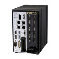
Vision System
Brand: Omron
|
Category: Industrial Equipment
|
Size: 22.21 MB
Table of Contents
-
Disclaimers15
-
Warning18
-
Grounding20
-
Others20
-
Maintenance23
-
All Series25
-
FH-L Series26
-
Terminology29
-
Monitor41
-
Accessories43
-
Cable44
-
Software46
-
FH-L Series53
-
FH-L Series55
-
FH-L Series74
-
Camera80
-
Camera Cable97
-
Lens108

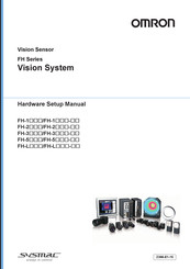
Omron FH-2 Series Hardware Setup Manual (244 pages)
Vision System
Brand: Omron
|
Category: Accessories
|
Size: 14.97 MB
Table of Contents
-
-
Maintenance22
-
Terminology
28 -
-
Monitor43
-
Accessories45
-
Cable46
-
Software48
-
Camera
79 -
Camera Cable
96 -
Lens
107-
Extension Tubes125
Omron FH-2 Series Hardware Setup Manual (244 pages)
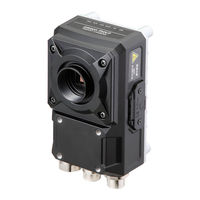
Vision Sensor
Brand: Omron
|
Category: Accessories
|
Size: 18.06 MB
Table of Contents
-
-
Fh-L3
-
Disclaimers15
-
Warning18
-
Grounding21
-
Others21
-
Maintenance24
-
All Series26
-
FH-L Series27
-
Terminology29
-
Fh-L£££-1037
-
Monitor41
-
Accessories43
-
Cable44
-
Software46
-
FH-L Series53
-
FH-L Series55
-
FH-L Series69
-
Camera75
-
Camera Cable92
-
Lens103
-
Extension Tubes121
-
LCD and Cable144
-
Sysmac Studio147
-
All Series150
-
FH-L Series153
-
All Series156
-
Setup and Wiring156
-
All Series159
-
FH-L Series165
-
All Series175
-
FH-L Series176
-
All Series177

Omron FH-2 Series Operation Manual (176 pages)
Vision System, for Sysmac Studio
Brand: Omron
|
Category: Industrial Equipment
|
Size: 5.56 MB
Table of Contents
-
Terminology
22 -
-
Overview27
-
-
-
-
Input Image98
-
Measurement98
-
Branch99
-
-
-
Editing an Area103
-
Color Extraction106
-
Color107
-
Binary107
-
List108

Omron FH-2 Series Instruction Sheet (2 pages)
Image Processing System
Brand: Omron
|
Category: Controller
|
Size: 0.56 MB
Advertisement