Sign In
Upload
Manuals
Brands
Olympus Manuals
Measuring Instruments
45MG
Olympus 45MG Manuals
Manuals and User Guides for Olympus 45MG. We have
2
Olympus 45MG manuals available for free PDF download: User Manual, Getting Started Manual
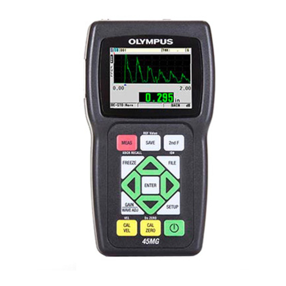
Olympus 45MG User Manual (246 pages)
ultrasonic thickness gage
Brand:
Olympus
| Category:
Measuring Instruments
| Size: 3.05 MB
Table of Contents
Table of Contents
3
DMTA-10022-01EN, Rev. C, January
8
List of Abbreviations
9
Figure I-1 the Symbols on the Top of the 45MG
11
Labels and Symbols
11
Figure I-2 Labels Attached to the Back of the Instrument
12
Table 1 Label Contents
13
Important Information - Please Read before Use
15
Intended Use
15
Instruction Manual
15
Instrument Compatibility
16
Repair and Modification
17
Safety Symbols
17
Safety Signal Words
18
Note Signal Words
18
Safety
19
Warnings
19
Battery Precautions
20
Equipment Disposal
21
WEEE Directive
21
China Rohs
21
EMC Directive Compliance
22
FCC (USA) Compliance
22
ICES-001 (Canada) Compliance
22
Regulatory Information
23
Warranty Information
23
Figure I-3 the REGULATORY Screen
23
Technical Support
24
Figure I-4 the 45MG Instrument
25
Introduction
25
1 Instrument Description
27
Product Description
27
DMTA-10022-01EN, Rev. C, January
28
Environmental Ratings
29
Instrument Hardware Components
29
Connectors
30
Figure 1-1 the 45MG Hardware Components - Front, Top, and Side Views
30
Figure 1-2 the 45MG Connections
30
Figure 1-3 the Top End Connectors
31
Figure 1-4 the Microsd Connector Behind the Battery Door
31
Keypad Functions
32
Figure 1-5 the 45MG Keypads
32
Table 2 Keypad Functions
33
2 Powering the 45MG
37
Power Indicator
37
Figure 2-1 the Power Indicator When Using Batteries
37
Battery Power
38
Battery Operating Time
38
Figure 2-2 the Power Indicator When Using a Computer or an AC Power Supply
38
Battery Level and Storage
39
Figure 2-3 Opening the Battery Compartment
39
Replacing the Batteries
39
Figure 2-4 Selecting the Battery Type
41
3 Software User Interface Elements
43
Measurement Screen
43
Figure 3-1 the Measurement Screen - no Waveform Enabled
43
Figure 3-2 the Measurement Screen - Waveform Option Enabled
44
Figure 3-3 the ID Bar
44
Figure 3-4 Other Elements - no Waveform Option Enabled
45
Figure 3-5 Other Elements - Waveform Option Enabled
46
Figure 3-6 the Loss-Of-Signal (LOS) Indicator
46
Menus and Submenus
47
Figure 3-7 Menu and Submenu Example
47
Parameter Screens
48
Figure 3-8 Parameter Screen Example
48
Selecting the Text Edit Mode
49
Editing Text Parameters Using the Virtual Keyboard
49
Figure 3-9 Example of the Virtual Keyboard
50
Editing Text Parameters Using the Traditional Method
51
Figure 3-10 the Character Cycle of the Traditional Text Edit Method
51
4 Initial Setup
53
Setting the User Interface Language and Other System Options
53
Selecting the Measurement Units
54
Setting the Clock
54
Figure 4-1 the SYSTEM Screen
54
Changing Display Settings
55
Figure 4-2 the SP MENU Screen
55
Figure 4-3 the CLOCK Screen
55
Figure 4-4 the DISPLAY Screen
56
Color Schemes
57
Figure 4-5 Example of the Indoor and the Outdoor Color Schemes
57
Display Brightness
58
Adjusting the Measurement Update Rate
58
Figure 4-6 the Measurement Update Rate Indicator
59
Changing the Thickness Resolution
60
5 Basic Operation
61
Setting up the Transducer
61
Figure 5-1 Plugging in the Transducer
62
Figure 5-2 Initial Screen with a Standard D79X Dual Element Transducer
62
Figure 5-3 Selecting a Default Single Element Transducer Setup
63
Calibration
64
Calibrating the Instrument
65
Figure 5-4 Sound Velocity Calibration on a Five-Step Test Block - Thick Part
65
Figure 5-5 Performing the Sound Velocity Calibration on a Five-Step Test Block
66
Figure 5-6 Sound Velocity Calibration on a Five-Step Test Block - Thin Part
66
Figure 5-7 Performing the Zero Calibration on a Five-Step Test Block
67
Figure 5-8 Example of a Five-Step Test Block
68
Test Blocks
68
Transducer Zero Compensation
68
Material Sound Velocity and the Zero Calibrations
69
Entering a Known Material Sound Velocity
70
Figure 5-9 Entering a Known Material Sound Velocity
70
Locked Calibrations
70
Factors Affecting Performance and Accuracy
71
Figure 5-10 the Calibration Lock Message
71
Measuring Thicknesses
73
Figure 5-11 Coupling a Dual Element Transducer
74
DMTA-10022-01EN, Rev. C, January
74
Saving Data
75
Figure 5-12 Reading the Measured Thickness
75
Figure 5-13 the Active File Name Appearing in the ID Bar
75
6 Software Options
77
Table 3 45MG Software Options
77
Activating Software Options
78
Figure 6-1 the OPTIONS Screen
79
Echo Detection Modes with Dual Element Transducers
80
Figure 6-2 Measuring with the Standard Echo Detection Mode
80
Figure 6-3 Measuring with the Automatic Echo-To-Echo Detection Mode
81
Figure 6-4 Measuring with the Manual Echo-To-Echo Detection Mode
82
Blanking Adjustments in Manual Echo-To-Echo Detection Mode
83
Dual Element Transducer Selection in Echo-To-Echo Modes
84
Figure 6-5 Comparing Manual Measurements
84
Table 4 Recommended Transducers for Various Steel Thickness Ranges
85
Enabling the THRU-COAT Function
86
Measurements with Optional THRU-COAT, D7906, and D7908 Transducers
86
Figure 6-6 Opening the THRU-COAT Setup Dialog Box
87
Performing a THRU-COAT Calibration
87
Waveform Software Option
88
Figure 6-7 Standard Display
89
Figure 6-8 Waveform Display
90
Waveform Rectification
90
Figure 6-9 Examples of the Rectification Modes
91
Figure 6-10 Examples of Waveform Trace Modes
92
Range of the Waveform Display
92
Waveform Trace
92
Figure 6-11 the Range of the Waveform Display
93
Selecting the Range Value
93
Activating the Zoom Function (Available Only with the Waveform Option)
94
Adjusting the Delay Value
94
Figure 6-12 Comparing the Normal and Zoomed Display in Mode 1
95
Figure 6-13 Comparing the Normal and Zoomed Display in Mode 2
95
Figure 6-14 Comparing the Normal and Zoomed Display in Mode 3
96
Single Element and High Resolution Option
96
Creating Custom Single Element Transducer Setups
97
High-Resolution Thickness
97
Recalling Single Element Transducer Setups
97
Datalogger Option
98
High-Penetration Software Option
98
Datalogger
99
Figure 6-15 the Active File Name Appears in the ID Bar
99
Table 5 File Contents Summary
99
Figure 6-16 Identifying Datalogger Parameters
100
Table 6 Additional Information Stored with the Data
101
Creating a Data File
102
Data File Types
103
Figure 6-17 Example of the CREATE Screen
103
Incremental Data File Type
104
Table 7 Resulting ID Examples for the INCREMENTAL File Type
104
Figure 6-18 the CREATE Screen for the Incremental Data File Type
105
Sequential Data File Type
106
Table 8 Resulting ID Examples for the SEQUENTIAL File Type
106
Figure 6-19 Selecting the ID Range for the Sequential File Type
107
Sequential with Custom Point Data File Type
107
Table 9 Resulting ID Example for the SEQ+CUSTOM PT File Type
107
2-D Grid Data File Type
108
Figure 6-20 Configuring ID Range for a Sequential with Custom Points Data File Type
108
Figure 6-21 General 2-D Grid Example
109
Figure 6-22 One Grid for 75 Identical Parts
110
Figure 6-23 Differently Named Grid for each Part
111
Boiler Data File Type
112
Figure 6-24 Configuring the ID Range for a 2-D Grid Data File Type
112
Table 10 Resulting ID Example for the BOILER File Type
113
Figure 6-25 Configuring the ID Range for a Boiler Data File Type
114
File Data Modes
114
Table 11 File Data-Mode Stored Measurements
114
Performing File Operations
115
Figure 6-26 the FILE Menu
116
Opening a File
116
Copying a File
117
Figure 6-27 Opening a File
117
Reviewing a File
117
Editing a File
118
Figure 6-28 Copying a File
118
Figure 6-29 Entering New File Information
120
Deleting a File or Its Contents
121
Figure 6-30 Displaying the Grid Edit Screen
121
Deleting a Range of Ids
122
Figure 6-31 Deleting a File
122
Deleting All Data Files
123
Figure 6-32 Deleting the Data of an ID Range in the Active File
123
Figure 6-33 Warning Message When Resetting Measurements
124
Figure 6-34 the MEMORY Status Screen
124
Viewing the Memory Status
124
Figure 6-35 the ID Overwrite Protection Message
125
ID Review Screen
125
Setting the ID Overwrite Protection
125
Figure 6-36 Identifying the ID Review Screen
126
Editing the ID
127
Reviewing Stored Data and Changing the Active ID
127
Figure 6-37 Editing the ID # Edit Mode
128
Figure 6-38 the Message When the Edited ID Is Not in the Database
128
Erasing Data in the Active File
129
Generating Reports
130
Figure 6-39 the FILE SUMMARY Report Screen
131
Figure 6-40 the FILE SUMMARY Report Result Screen
131
Figure 6-41 the MIN/MAX SUMMARY Report Screen
132
Figure 6-42 the FILE COMPARISON Report Screen
133
Figure 6-43 the FILE COMPARISON Report Result Screen
133
Figure 6-44 the ALARM SUMMARY Report Result Screen
134
Figure 6-45 the MIN/MAX SUMMARY Report Result Screen
134
Figure 6-46 Returning to the Measurement Screen
135
7 Using Special Functions
137
Activating and Configuring a Differential Mode
137
Figure 7-1 Normal Differential Mode (Shown with Waveform Option Activated)
137
Using the Minimum, Maximum, or Min/Max Thickness Mode
139
Figure 7-2 the DIFF Screen
139
Figure 7-3 Displaying the Minimum And/Or Maximum Thickness (Shown with the Waveform Option Activated)
140
Preventing False Minimum/Maximum Thickness Readings
141
Using Alarms
141
Figure 7-4 Example of a HIGH Alarm Indicator (Shown with the Waveform Option Activated)
142
Figure 7-5 Example of a B-Scan Alarm Mode
143
Figure 7-6 YEL (Yellow) and RED Alarm Indicators (Shown with the Waveform Option Activated)
144
Figure 7-7 Setting up the STANDARD Alarm
145
Locking the Instrument
146
Figure 7-8 Example of a Locked Function Message in the Help Bar
147
Figure 7-9 the PASSWORD Screen
147
Freezing the Measurement or Optional Waveform
148
Figure 7-10 the LOCKS Screen
148
8 Configuring the Instrument
151
Configuring Measurement Parameters
151
Figure 8-1 the MEAS Screen
152
Configuring System Parameters
154
Figure 8-2 the SYSTEM Screen
154
Configuring Communications
155
Figure 8-3 the COMM Screen
157
9 Using Advanced Gaging Features
159
Adjusting the Gain with Dual Element Transducers
159
Figure 9-1 Manually Adjusting the Gain
160
Adjusting the Extended Blank with Dual Element Transducers
161
Figure 9-2 Adjusting the Extended Blank Length
162
B-Scan
163
Figure 9-3 B-Scan Example
163
Figure 9-4 Changing B-Scan Parameters
164
Figure 9-5 B-Scan Elements
165
Figure 9-6 B-Scan Freeze Review Elements
166
Using the B-Scan
166
Saving B-Scans or Thickness Readings (Optional Datalogger)
167
Using the B-Scan Alarm Mode
167
DB Grid
169
Figure 9-7 Example of the Half-Size DB Grid
169
Activating and Configuring the DB Grid
170
Figure 9-8 Changing DB Grid Parameters
170
Figure 9-9 Grid Transposition Example
170
Figure 9-10 Example of a Linearized DB Grid
171
Changing the Highlighted Cell in the DB Grid
172
Figure 9-11 the Highlighted DB Grid Cell in the ID Review Screen
172
Figure 9-12 Example of an Inserted Cell
173
Saving Thickness Readings in the DB Grid
173
Viewing an Inserted or an Appended Cell in the DB Grid
173
Figure 9-13 Example of a Zoomed Inserted Cell
174
10 Custom Setups for Single Element Transducers
175
10.1 Creating a Custom Setup for a Single Element Transducer
175
Figure 10-1 the ACTIVE Screen for the Setup of a Single Element Transducer
176
Quickly Adjusting Waveform Parameters for Single Element Transducers
178
Figure 10-2 Adjusting the Waveform Parameters
178
10.3 Detection Modes
179
Figure 10-3 Mode 1 Detection Example
180
Figure 10-4 Mode 2 Detection Example
180
10.4 First Peak
181
Figure 10-5 Mode 3 Detection Example
181
10.5 Pulser Power
182
Figure 10-6 Detection of the First or the Second Negative Peak
182
10.6 Time-Dependent Gain Curve
183
Figure 10-7 Comparing Pulser Powers Set to 60 V and 200 V
183
Figure 10-8 the TDG Zones and Parameters
184
Maximum Gain
184
Initial Gain
185
TDG Slope
185
10.7 Main Bang Blank
185
DMTA-10022-01EN, Rev. C, January
185
Figure 10-9 Main Bang Blank Position for Mode 1
186
10.8 Echo Window
187
Figure 10-10 Main Bang Blank Position for Mode 2 and Mode 3
187
Figure 10-11 Echo Window Setting for Mode 1
188
Figure 10-12 Echo Window Setting for Mode 2 and Mode 3
188
Detection of Echo 1 and Echo 2
189
Figure 10-13 Negative and Positive Echo Detection Examples
189
Interface Blank
190
Table 12 Polarity of Echoes
190
Figure 10-14 Examples of the Interface Blank in Mode 2
191
Figure 10-15 Examples of the Interface Blank in Mode 3
192
Figure 10-16 Examples of M3 Blank Adjustment
192
Mode 3 Echo Blank
192
10.9 Saving Setup Parameters
193
10.10 Quickly Recalling a Custom Setup for Single Element Transducers
194
Figure 10-17 Saving Custom Setups
194
11 Managing Communications and Data Transfer
197
11.1 Gageview
197
11.2 Setting up USB Communication
197
Figure 11-1 Connecting the 45MG to a Computer
198
11.3 Exchanging Data with a Remote Device
199
Exporting a File to the Memory Card (Datalogger Option Only)
199
Figure 11-2 the EXPORT Screen
200
Importing Survey Files from the External Memory Card
200
Figure 11-3 Example of the IMPORT Screen
201
Receiving Files from a Computer
202
11.4 Capturing Screen Images
203
Sending a Screen Capture to Gageview
203
Figure 11-4 the Device Configuration Dialog Box
204
Figure 11-5 the Device Tools Dialog Box with a Screen Capture
205
Sending a Screen Capture to the External Microsd Card
205
11.5 Resetting the Communication Parameters
206
Table 13 Default Communication Parameter Values
206
Figure 11-6 Selecting COMMUNICATION RESET
207
12 Maintaining and Troubleshooting the 45MG
209
12.1 Routine Gage Handling
209
12.2 Cleaning the Instrument
210
12.3 Maintaining Transducers
210
12.4 Using Instrument Resets
210
Table 14 Measurement Default Settings
211
Table 15 Default Communication Settings
212
12.5 Performing Hardware Diagnostic Tests
213
Figure 12-1 Activating a Reset Function
213
Figure 12-2 the KEYPAD TEST Screen
214
12.6 Performing the Software Diagnostic Test
215
Figure 12-3 the DUAL XDCR TEST Screen
215
12.7 Viewing the Instrument Status
216
Figure 12-4 Example of the SW DIAG Screen
216
12.8 Understanding Error Messages
217
12.9 Resolving Battery Problems
217
Figure 12-5 Example of the STATUS Screen
217
12.10 Resolving Measurement Problems
218
Table 16 Measurement Troubleshooting
218
Appendix A: Technical Specifications
219
Table 17 General EN15317 Specifications
219
Table 18 Display EN15317 Specifications
220
Table 19 Transmitter EN15317 Specifications
220
Table 20 Receiver EN15317 Specifications
220
Table 21 Other EN15317 Specifications
220
Table 22 Environmental Rating Specifications
221
Table 23 Measurement Specifications
221
Table 24 Datalogger Specifications
222
Table 25 Typical Ranges and Default Setups for Single Element Transducers
222
Table 26 Setup Parameter Description
224
Table 27 General Specifications
225
Appendix B: Sound Velocities
227
Table 28 Sound Velocities in Common Materials
227
Appendix C: Accessories and Replacement Parts
229
Table 29 Software Options
229
Table 30 Accessories and Replacement Parts
229
Table 31 Interface Cables and Power Accessories
230
Table 32 Couplants
230
Table 33 Test Blocks
230
List of Figures
233
Advertisement
Olympus 45MG Getting Started Manual (8 pages)
Brand:
Olympus
| Category:
Measuring Instruments
| Size: 0.46 MB
Advertisement
Related Products
Olympus STYLUS 400 Digital
Olympus 4TI
Olympus D-40 - Camedia 4MP Digital Camera
Olympus Stylus 410
Olympus Master 4.1
Olympus Stylus 400 - Stylus 400 4MP Digital Camera
Olympus CAMEDIA Master 4.3/Pro
Olympus DS 40 - 512 MB Digital Voice Recorder
Olympus M.ZUIKO DIGITAL 45mm f1.8
Olympus 27MG
Olympus Categories
Digital Camera
Voice Recorder
Microscope
Camera Accessories
Camera Lens
More Olympus Manuals
Login
Sign In
OR
Sign in with Facebook
Sign in with Google
Upload manual
Upload from disk
Upload from URL