Sign In
Upload
Manuals
Brands
Olympus Manuals
Test Equipment
38DL PLUS
Olympus 38DL PLUS Manuals
Manuals and User Guides for Olympus 38DL PLUS. We have
2
Olympus 38DL PLUS manuals available for free PDF download: User Manual, Basic Operation Manual
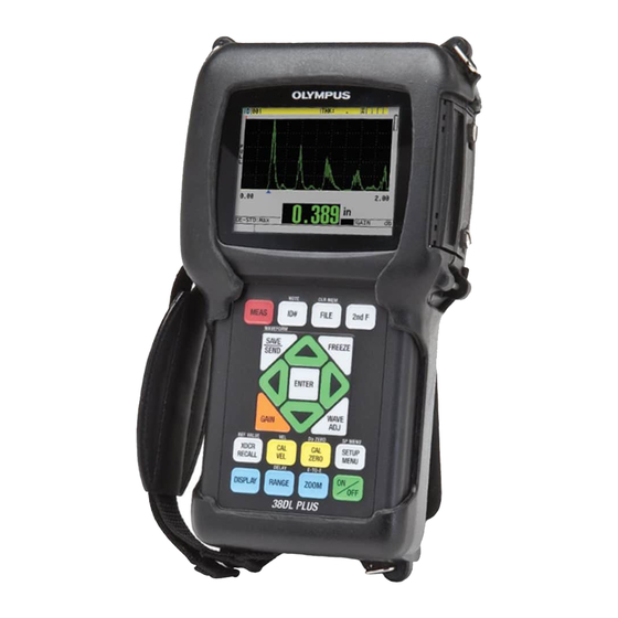
Olympus 38DL PLUS User Manual (318 pages)
Ultrasonic Thickness Gage
Brand:
Olympus
| Category:
Measuring Instruments
| Size: 6.2 MB
Table of Contents
Table of Contents
3
List of Abbreviations
11
Figure I-1 the Warning Symbol between the T/R Connectors
13
Labels and Symbols
13
Figure I-2 Labels and Symbols Are Attached to the Instrument
14
Table 1 Label Contents
15
Important Information - Please Read before Use
17
Intended Use
17
Instruction Manual
17
Instrument Compatibility
18
Repair and Modification
19
Safety Symbols
19
Safety Signal Words
19
Note Signal Words
20
Safety
21
Warnings
21
Battery Precautions
22
Equipment Disposal
23
CE (European Community)
23
WEEE Directive
24
China Rohs
24
EMC Directive Compliance
25
FCC (USA) Compliance
25
ICES-001 (Canada) Compliance
26
Regulatory Information
26
Warranty Information
26
Technical Support
27
Figure I-3 the 38DL PLUS Instrument
29
Introduction
29
1 Instrument Description
31
Product Description
31
Figure 1-1 Measuring Thicknesses with the 38DL PLUS
31
Environmental Ratings
34
Instrument Hardware Components
34
Connectors
35
Figure 1-2 the 38DL PLUS Hardware Components
35
Figure 1-3 the 38DL PLUS Connections
35
Figure 1-4 the Top End Connectors
36
Keypad Functions
37
Figure 1-5 the Connectors Behind the I/O Door
37
Figure 1-6 the 38DL PLUS Keypads
38
Table 2 Keypad Functions
39
2 Powering the 38DL PLUS
43
Power Indicator
43
Figure 2-1 the Power Indicator for Battery and AC Operation
43
Using the AC Power
44
Figure 2-2 Connecting the Charger/Adaptor
44
Using Battery Power
45
Figure 2-3 Connecting the DC Power Plug
45
Battery Operating Time
46
Charging the Battery
46
Figure 2-4 Opening the Battery Compartment
48
Replacing the Battery
48
Figure 2-5 Selecting the New Battery Type
49
3 Software User Interface Elements
51
Measurement Screen
51
Figure 3-1 the Main Elements of the Measurement Screen
51
Figure 3-2 the ID Bar
52
Menus and Submenus
53
Figure 3-3 Example of Other Elements Appearing on the Measurement Screen
53
Figure 3-4 the Loss-Of-Signal (LOS) Indicator
53
Parameter Screens
54
Figure 3-5 Menu and Submenu Example
54
Figure 3-6 Parameter Screen Example
55
Selecting the Text Edit Mode
56
Editing Text Parameters Using the Virtual Keyboard
56
Figure 3-7 Example of the Virtual Keyboard
57
Editing Text Parameters Using the Traditional Method
58
Figure 3-8 the Character Cycle of the Traditional Text Edit Method
58
4 Initial Setup
61
Setting the User Interface Language and Other System Options
61
Selecting the Measurement Units
62
Setting the Clock
62
Figure 4-1 Selecting the User Interface Language
62
Changing Display Settings
63
Figure 4-2 Selecting Clock Parameters
63
Color Schemes
64
Figure 4-3 the DISPLAY SETTINGS Screen
64
Display Brightness
65
Figure 4-4 Example of the Indoor and the Outdoor Color Schemes
65
Figure 4-5 Examples of the Rectification Modes
66
Waveform Rectification
66
Waveform Trace
67
Range of the Waveform Display
68
Figure 4-6 Examples of Waveform Trace Modes
68
Figure 4-7 the Range of the Waveform Display
69
Selecting the Range Value
69
Activating the Zoom Function
70
Adjusting the Delay Value
70
Figure 4-8 Comparing Normal and Zoomed Display in Mode 1
71
Figure 4-9 Comparing Normal and Zoomed Display in Mode 2
71
Adjusting the Measurement Update Rate
72
Figure 4-10 Comparing Normal and Zoomed Display in Mode 3
72
Figure 4-11 the Measurement Update Rate Indicator
72
Changing the Thickness Resolution
73
5 Basic Operation
75
Setting up the Transducer
75
Figure 5-1 Plugging the Transducer
76
Figure 5-2 Initial Screen with a Standard D79X Dual Element Transducer
76
Figure 5-3 Selecting a Default Single Element Transducer Setup
77
Calibration
78
Calibrating the Instrument
79
Figure 5-4 Performing the Material Sound Velocity Calibration on a 5-Step Test Block
80
Figure 5-5 Performing the Zero Calibration on a 5-Step Test Block
81
Figure 5-6 Example of a 5-Step Test Block
82
Test Blocks
82
Transducer Zero Compensation
82
Material Sound Velocity and the Zero Calibrations
83
Entering a Known Material Sound Velocity
84
Figure 5-7 Entering a Known Material Sound Velocity
84
Factors Affecting the Performance and the Accuracy
85
Figure 5-8 the Calibration Lock Message
85
Locked Calibrations
85
Measuring Thicknesses
87
Saving Data
88
Figure 5-9 Coupling Dual Element Transducer and Reading the Measured Thickness
88
Figure 5-10 the Active File Name Appearing in the ID Bar
89
Measurements with THRU-COAT D7906 and D7908 Transducers
90
Enabling the THRU-COAT Function
90
Figure 5-11 Opening the THRU COAT SETUP Dialog Box
90
Performing a THRU-COAT Calibration
91
Echo Detection Modes with Dual Element Transducers
92
Figure 5-12 Measuring with the Standard Echo Detection Mode
92
Figure 5-13 Measuring with the Automatic Echo-To-Echo Detection Mode
93
Figure 5-14 Measuring with the Manual Echo-To-Echo Detection Mode
94
Blanking Adjustments in Manual Echo-To-Echo Detection Mode
95
Dual Element Transducer Selection in Echo-To-Echo Modes
96
Figure 5-15 Comparing Manual Measurements
96
Table 3 Recommended Transducers for Various Steel Thickness Ranges
96
Echo-To-Echo Mode Datalogger Flags
97
Using the VGA Output
98
6 Using EMAT Transducers
99
Connecting the E110-SB EMAT Transducer
100
Figure 6-1 EMAT Transducer and Filter Adaptor Connection
100
Calibrating with the E110-SB EMAT Transducer
101
7 Software Options
103
Table 4 38DL PLUS Software Options
103
Activating Software Options
104
Figure 7-1 the OPTIONS Screen to Activate Software Options
104
High Resolution Software Option
105
Oxide Layer Software Option
105
Steam Boiler Tube Scale
106
Table 5 Oxide Layer Transducers
106
Figure 7-2 the OXIDE Screen
107
Setting up for Oxide Layer Measurement
107
Calibrating for Oxide Layer Measurement
108
Figure 7-3 Selecting Which Measurement Appears with the Larger Font
108
Figure 7-4 Measurement Screen with the Oxide Layer Software Option
109
Measuring Boiler Tube and Oxide Layer Thicknesses
109
Figure 7-5 Measurement Screen for a Disbonded Oxide Layer
110
Multi-Measurement Software Option
111
Active Measurement
112
Figure 7-6 Waveform Display Screen
112
Using the Multi-Measurement Normal Mode
112
Figure 7-7 Setting Multi-Measurement Parameters in the Normal Mode
113
Figure 7-8 Multi-Measurement Display Modes with Three Layers and the Sum
114
Using the Multi-Measurement with the Soft Contact Mode
114
Figure 7-9 Setting Multi-Measurement Parameters in the Soft Contact Mode
116
Using the Multi-Measurement % Total Thickness Mode
116
Encoded B-Scan Option
117
Figure 7-10 Setting Multi-Measurement Parameters in the % Total Thickness Mode
117
Figure 7-11 Encoded B-Scan Main Screen
118
Figure 7-12 Changing B-Scan Parameters
119
Table 6 Sample Scan-Speed Calculations
120
Table 7 Sample Maximum-Distance Calculations
121
Figure 7-13 7 Inch Scan Zoom Set to 1
122
Figure 7-14 7 Inch Scan Zoom Set to 5
122
Figure 7-15 7 Inch Scan Zoom Set to 10
123
High Penetration Software Option
123
8 Using Special Functions
125
Activating and Configuring a Differential Mode
125
Figure 8-1 Normal Differential Mode
125
Using the Minimum, Maximum, or Min/Max Thickness Mode
127
Figure 8-2 the DIFF Screen
127
Figure 8-3 Displaying the Minimum And/Or Maximum Thickness
128
Preventing False Minimum/Maximum Thickness Readings
129
Using Alarms
129
Figure 8-4 Example of a HIGH Alarm Indicator
130
Table 8 Alarm Calculation Example with the ABSOLUTE DIFF Mode
131
Table 9 Alarm Calculation Example with the % DIFF Mode
132
Figure 8-5 Example of a B-Scan Alarm Mode
133
Figure 8-6 YEL (Yellow) and RED Alarm Indicators
134
Figure 8-7 Setting up the STANDARD Alarm
135
Locking the Instrument
136
Figure 8-8 Example of a Locked Function Message in the Help Bar
136
Figure 8-9 the INSTRUMENT LOCK Screen
137
Freezing Waveforms
138
9 Configuring the Instrument
139
Configuring Measurement Parameters
139
Figure 9-1 the MEAS Screen
139
Configuring System Parameters
141
Figure 9-2 the SYSTEM Screen
142
Configuring Communications
143
Figure 9-3 Changing the Communication Parameters
144
10 Using Advanced Gaging Features
147
Adjusting the Gain with Dual Element and E110 EMAT Transducers
147
Figure 10-1 Manually Adjusting the Gain
148
Adjusting the Extended Blank with Dual Element Transducers
149
Figure 10-2 Adjusting the Extended Blank Length
150
B-Scan
151
Figure 10-3 B-Scan Example for a 5-Step Test Block
151
Figure 10-4 Changing B-Scan Parameters
152
Figure 10-5 the Half-Size and Full-Size B-Scans
153
Figure 10-6 B-Scan Elements
153
Figure 10-7 B-Scan Freeze Review Elements
155
Using the B-Scan
156
Using the B-Scan Alarm Mode
156
Saving B-Scans, A-Scans, or Thickness Readings
157
DB Grid
159
Activating and Configuring the DB Grid
159
Figure 10-8 Example of the Half-Size DB Grid
159
Figure 10-9 Changing DB Grid Parameters
160
Figure 10-10 Example of Half-Size and Full-Size DB Grids
161
Figure 10-11 Grid Transposition Example
161
Changing the Highlighted Cell in the DB Grid
162
Figure 10-12 Example of a Linearized DB Grid
162
Figure 10-13 the Highlighted DB Grid Cell in the ID Review Screen
163
Figure 10-14 Example of an Inserted Cell
164
Saving Thickness Readings in the DB Grid
164
Viewing an Inserted or an Appended Cell in the DB Grid
164
Configuring AVG/MIN Measurements
165
Figure 10-15 Example of a Zoomed Inserted Cell
165
Making AVG/MIN Measurements
166
Figure 10-16 Opening the Avg/Min Measure Dialog Box
166
Figure 10-17 Examples of the Measurement Screen with the AVG/MIN Measurement Active
167
Using Temperature Compensation
168
Figure 10-18 the TEMP COMP Screen
169
Figure 10-19 Displaying Temperature Compensation Data
170
11 Using the Datalogger
171
Datalogger
171
Figure 11-1 the Active File Name Appearing in the ID Bar
171
Table 10 File Contents Summary
172
Figure 11-2 Identifying Datalogger Parameters
173
Table 11 Additional Information Stored with the Data
174
Creating a Data File
175
Figure 11-3 Example of the CREATE Screen
176
Data File Types
177
Incremental Data File Type
177
Table 12 Resulting ID Examples for the INCREMENTAL File Type
178
Figure 11-4 the CREATE Screen for the Incremental Data File Type
179
Sequential Data File Type
179
Table 13 Resulting ID Examples for the SEQUENTIAL File Type
179
Figure 11-5 Selecting the ID Range for the Sequential File Type
180
Sequential with Custom Points Data File Type
180
Table 14 Resulting ID Example for the SEQ+CUSTOM PT File Type
181
2-D Grid Data File Type
182
Figure 11-6 Configuring the ID Range for a Sequential with Custom Points Data File Type
182
Figure 11-7 General 2-D Grid Example
183
Figure 11-8 One Grid for 75 Identical Parts
184
Figure 11-9 Different Named Grid for each Part
185
2-D Grid with Custom Points Data File Type
186
Figure 11-10 Configuring the ID Range for a 2-D Grid Data File Type
186
Table 15 Resulting ID Example for the 2D+CUSTOM PT File Type
187
3-D Grid Data File Type
188
Figure 11-11 Configuring the ID Range for a 2-D Grid with Custom Points Data File Type
188
Table 16 Resulting ID Example for the 3-D GRID File Type
189
Boiler Data File Type
190
Figure 11-12 Configuring the ID Range for a 3-D Grid Data File Type
190
Table 17 Resulting ID Example for the BOILER File Type
191
3-D Custom File Type
192
Figure 11-13 Configuring the ID Range for a Boiler Data File Type
192
Table 18 Resulting ID Example for the 3-D CUSTOM File Type
192
Figure 11-14 Configuring the ID Range for a 3-D Custom Data File Type
193
File Data Modes
194
Table 19 File Data Mode Stored Measurements
194
Performing File Operations
195
Figure 11-15 the File Menu and Report Submenu
196
Opening a File
196
Copying a File
197
Figure 11-16 Opening a File
197
Editing a File
198
Figure 11-17 Copying a File
198
Figure 11-18 Entering New File Information
199
Deleting a File or Its Contents
200
Figure 11-19 Displaying the Grid Edit Screen
200
Figure 11-20 Deleting a File
201
Deleting a Range of Ids
202
Deleting All Data Files
202
Figure 11-21 Deleting the Data of an ID Range in the Active File
202
Figure 11-22 Warning Message When Resetting Measurements
203
Notes
204
Creating or Editing Notes
204
Figure 11-23 the FILE NOTES Screen
204
Associating a Note to an ID or to a Range of Ids
205
Deleting a Note from a File
206
Figure 11-24 Selecting a Note from the Notes Table
206
Copying a Note Table
207
Setting the ID Overwrite Protection
208
Figure 11-25 Copying a Note Table from One File to Another
208
ID Review Screen
209
Figure 11-26 the ID Overwrite Protection Message
209
Figure 11-27 Identifying the ID Review Screen
210
Editing the ID
211
Reviewing Stored Data and Changing the Active ID
211
Figure 11-28 Editing the ID # Edit Mode
212
Erasing Data in the Active File
213
Figure 11-29 the Message When the Edited ID Is Not in the Database
213
Generating Reports
214
Figure 11-30 the FILE SUMMARY Report Screen
215
Figure 11-31 the FILE SUMMARY Report Result Screen
216
Figure 11-32 the MIN/MAX SUMMARY Report Screen
216
Figure 11-33 the FILE COMPARISON Report Screen
217
Figure 11-34 the FILE COMPARISON Report Result Screen
218
Figure 11-35 the ALARM SUMMARY Report Result Screen
219
Figure 11-36 the MIN/MAX SUMMARY Report Result Screen
220
Figure 11-37 Returning to the Measurement Screen
220
12 Dual Element Transducer Setups
223
Standard D79X and Other Dual Element Transducers
223
Table 20 Predefined Setups
223
Creating a Setup for Nonstandard Dual Element Transducers
224
Figure 12-1 the GENERIC SETUP SELECTION Screen
225
Table 21 Default Transducers
225
Figure 12-2 Example of the ACTIVE Screen
226
Recalling Stored Dual Element Transducer Setups
227
V-Path
227
Activating the V-Path Function
228
Building a V-Path Correction Curve for a Nonstandard Dual Element Transducer
228
Figure 12-3 Illustration of the V-Path
228
Figure 12-4 Answering YES at the V-Path Calibration Prompt
230
Figure 12-5 Editing Point 1 of the V-Path Calibration
231
Figure 12-6 Saving the Setup
232
13 Custom Setups for Single Element Transducers
233
Creating a Custom Setup for a Single Element Transducer
233
Figure 13-1 the ACTIVE Screen for the Setup of a Single Element Transducer
234
Quickly Adjusting Waveform Parameters for Single Element Transducers
236
Figure 13-2 Adjusting the Waveform Parameters
236
Detection Modes
237
Figure 13-3 Mode 1 Detection Example
238
Figure 13-4 Mode 2 Detection Example
238
First Peak
239
Figure 13-5 Mode 3 Detection Example
239
Pulser Power
240
Figure 13-6 Detection of the First or the Second Negative Peak
240
Time-Dependent Gain Curve
241
Figure 13-7 Comparing Pulser Power Set to 60 V and 200 V
241
Figure 13-8 the TDG Zones and Parameters
242
Maximum Gain
242
Initial Gain
243
TDG Slope
243
Main Bang Blank
244
Figure 13-9 Main Bang Blank Position for Mode 1
244
Echo Window
245
Figure 13-10 Main Bang Blank Position for Mode 2 and Mode 3
245
Figure 13-11 Echo Window Setting for Mode 1
246
Figure 13-12 Echo Window Setting for Mode 2 and Mode 3
246
Detection of Echo 1 and Echo 2
247
Figure 13-13 Negative and Positive Echo Detection Examples
247
Interface Blank
248
Table 22 Polarity of Echoes
248
Figure 13-14 Examples of the Interface Blank in Mode 2
249
Figure 13-15 Examples of the Interface Blank in Mode 3
250
Mode 3 Echo Blank
250
Saving Setup Parameters
251
Figure 13-16 Examples of M3 Blank Adjustment
251
Quickly Recalling a Custom Setup for Single Element Transducers
252
Figure 13-17 Saving Custom Setups
252
14 Managing Communications and Data Transfer
255
Gageview
255
Setting up USB Communication
256
Setting up RS-232 Serial Communication
257
Figure 14-1 Connecting the 38DL PLUS to a Computer
257
Table 23 Optional RS-232 Cables
258
Figure 14-2 Viewing Communication Parameters
259
Exchanging Data with a Remote Device
260
Sending Entire Files (RS-232)
260
Figure 14-3 Selecting a File to Send
261
Sending an ID Range from a File (RS-232)
261
Figure 14-4 Identifying a Range of ID Numbers to Send
262
Sending the Currently Displayed Measurement (RS-232)
262
Exporting a File to the External Memory Card
263
Figure 14-5 the EXPORT Screen
264
Importing Survey Files from the External Memory Card
264
Figure 14-6 Example of the IMPORT Screen
265
Receiving Files from a Computer
266
Capturing 38DL PLUS Screen Images
267
Sending a Screen Capture to Gageview
267
Figure 14-7 the Device Configuration Dialog Box
268
Figure 14-8 the Device Tools Dialog Box with a Screen Capture
269
Sending a Screen Capture to the External Microsd Card
269
Serial Data Output Formats
270
Table 24 Serial Data Output Format for Dual Element Transducers
270
Table 25 Serial Data Output Format for Single Element Transducers
271
Resetting the Communication Parameters
272
Figure 14-9 Viewing or Changing the File Output Format
272
Table 26 Default Communication Parameter Values
272
Figure 14-10 Selecting the COMMUNICATION RESET
273
15 Maintaining and Troubleshooting the 38DL PLUS
275
Providing Routine Gage Maintenance
275
Cleaning the Instrument
276
Maintaining Transducers
276
Using Instrument Resets
276
Table 27 Measurement Default Settings
277
Table 28 Default Communication Settings
278
Performing Hardware Diagnostic Tests
279
Figure 15-1 Activating a Reset Function
279
Figure 15-2 the KEYPAD TEST Screen
280
Performing the Software Diagnostic Test
281
Figure 15-3 the DUAL XDCR TEST Screen
281
Viewing the Instrument Status
282
Figure 15-4 Example of the SW DIAG Screen
282
Understanding Error Messages
283
Resolving Battery Pack and Charger Problems
283
Figure 15-5 Example of the STATUS Screen
283
Resolving Measurement Problems
284
Table 29 Measurement Troubleshooting
284
Appendix A: Technical Specifications
287
Table 30 General EN15317 Specifications
287
Table 31 Display EN15317 Specifications
288
Table 32 Transmitter EN15317 Specifications
288
Table 33 Receiver EN15317 Specifications
288
Table 34 Other EN15317 Specifications
288
Table 35 Environmental Rating Specifications
289
Table 36 Measurement Specifications
290
Table 37 Datalogger Specifications
290
Table 38 Typical Measurement Ranges and Default Setups for a Single Element Transducer
291
Table 39 Setup Parameter Description
293
Table 40 General Specifications
293
Appendix B: Sound Velocities
295
Table 41 Sound Velocities in Common Materials
295
Appendix C: Accessories and Replacement Parts
297
Table 43 Accessories and Replacement Parts
297
Table 44 Interface Cables and Power Accessories
298
Table 45 Couplants
299
Table 46 Test Blocks
299
List of Figures
301
List of Tables
307
Table 42 Software Options
309
Advertisement
Olympus 38DL PLUS Basic Operation Manual (112 pages)
Ultrasonic Thickness Gage
Brand:
Olympus
| Category:
Test Equipment
| Size: 2.37 MB
Table of Contents
Table of Contents
3
DMTA-10009-01EN [U8778346], Rev. D, November
6
List of Abbreviations
7
Figure I-1 the Warning Symbol between the T/R Connectors
9
Labels and Symbols
9
Figure I-2 Labels and Symbols Are Attached to the Instrument
10
Table 1 Label Contents
11
Important Information - Please Read before Use
13
Intended Use
13
Instruction Manual
13
Instrument Compatibility
14
Repair and Modification
15
Safety Symbols
15
Safety Signal Words
15
Note Signal Words
16
Safety
17
Warnings
17
Battery Precautions
18
Equipment Disposal
19
CE (European Community)
19
WEEE Directive
20
China Rohs
20
EMC Directive Compliance
21
FCC (USA) Compliance
21
ICES-001 (Canada) Compliance
22
Regulatory Information
22
Warranty Information
22
Technical Support
23
Figure I-3 the 38DL PLUS Instrument
25
Introduction
25
1 Instrument Description
27
Product Description
27
Figure 1-1 Measuring Thicknesses with the 38DL PLUS
28
DMTA-10009-01EN [U8778346], Rev. D, November
28
Environmental Ratings
30
Instrument Hardware Components
31
Figure 1-2 the 38DL PLUS Hardware Components
31
Connectors
32
Figure 1-3 the 38DL PLUS Connections
32
Figure 1-4 the Top End Connectors
33
Figure 1-5 the Connectors Behind the I/O Door
33
Keypad Functions
34
Figure 1-6 the 38DL PLUS Keypads
34
Table 2 Keypad Functions
35
2 Powering the 38DL PLUS
39
Power Indicator
39
Figure 2-1 the Power Indicator for Battery and AC Operation
39
Using the AC Power
40
Figure 2-2 Connecting the Charger/Adaptor
40
Using Battery Power
41
Figure 2-3 Connecting the DC Power Plug
41
Battery Operating Time
42
Charging the Battery
42
Replacing the Battery
44
Figure 2-4 Opening the Battery Compartment
44
Figure 2-5 Selecting the New Battery Type
45
3 Software User Interface Elements
47
Measurement Screen
47
Figure 3-1 the Main Elements of the Measurement Screen
47
Figure 3-2 the ID Bar
48
Menus and Submenus
49
Figure 3-3 Example of Other Elements Appearing on the Measurement Screen
49
Figure 3-4 the Loss-Of-Signal (LOS) Indicator
49
Parameter Screens
50
Figure 3-5 Menu and Submenu Example
50
Figure 3-6 Parameter Screen Example
51
Selecting the Text Edit Mode
52
Editing Text Parameters Using the Virtual Keyboard
52
Figure 3-7 Example of the Virtual Keyboard
53
Editing Text Parameters Using the Traditional Method
54
Figure 3-8 the Character Cycle of the Traditional Text Edit Method
54
4 Initial Setup
57
Setting the User Interface Language and Other System Options
57
Selecting the Measurement Units
58
Setting the Clock
58
Figure 4-1 Selecting the User Interface Language
58
Changing Display Settings
59
Figure 4-2 Selecting Clock Parameters
59
Color Schemes
60
Figure 4-3 the DISPLAY SETTINGS Screen
60
Display Brightness
61
Figure 4-4 Example of the Indoor and the Outdoor Color Schemes
61
Waveform Rectification
62
Figure 4-5 Examples of the Rectification Modes
62
Waveform Trace
63
Range of the Waveform Display
64
Figure 4-6 Examples of Waveform Trace Modes
64
Selecting the Range Value
65
Figure 4-7 the Range of the Waveform Display
65
Adjusting the Delay Value
66
Activating the Zoom Function
66
Figure 4-8 Comparing Normal and Zoomed Display in Mode 1
67
Figure 4-9 Comparing Normal and Zoomed Display in Mode 2
67
Adjusting the Measurement Update Rate
68
Figure 4-10 Comparing Normal and Zoomed Display in Mode 3
68
Figure 4-11 the Measurement Update Rate Indicator
68
Changing the Thickness Resolution
69
5 Basic Operation
71
Setting up the Transducer
71
Figure 5-1 Plugging the Transducer
72
Figure 5-2 Initial Screen with a Standard D79X Dual Element Transducer
72
Figure 5-3 Selecting a Default Single Element Transducer Setup
73
Calibration
74
Calibrating the Instrument
75
DMTA-10009-01EN [U8778346], Rev. D, November
75
Figure 5-4 Performing the Material Sound Velocity Calibration on a 5-Step Test Block
76
Figure 5-5 Performing the Zero Calibration on a 5-Step Test Block
77
Test Blocks
78
Transducer Zero Compensation
78
Figure 5-6 Example of a 5-Step Test Block
78
Material Sound Velocity and the Zero Calibrations
79
Entering a Known Material Sound Velocity
80
Figure 5-7 Entering a Known Material Sound Velocity
80
Locked Calibrations
81
Factors Affecting the Performance and the Accuracy
81
Figure 5-8 the Calibration Lock Message
81
Measuring Thicknesses
83
Saving Data
84
Figure 5-9 Coupling Dual Element Transducer and Reading the Measured Thickness
84
Figure 5-10 the Active File Name Appearing in the ID Bar
85
Measurements with THRU-COAT D7906 and D7908 Transducers
86
Enabling the THRU-COAT Function
86
Figure 5-11 Opening the THRU COAT SETUP Dialog Box
86
Performing a THRU-COAT Calibration
87
Echo Detection Modes with Dual Element Transducers
88
Figure 5-12 Measuring with the Standard Echo Detection Mode
88
Figure 5-13 Measuring with the Automatic Echo-To-Echo Detection Mode
89
Figure 5-14 Measuring with the Manual Echo-To-Echo Detection Mode
90
Blanking Adjustments in Manual Echo-To-Echo Detection Mode
91
Dual Element Transducer Selection in Echo-To-Echo Modes
92
Figure 5-15 Comparing Manual Measurements
92
Table 3 Recommended Transducers for Various Steel Thickness Ranges
92
Echo-To-Echo Mode Datalogger Flags
93
Using the VGA Output
94
Appendix: Technical Specifications
95
Table 4 General EN15317 Specifications
95
Table 5 Display EN15317 Specifications
96
Table 6 Transmitter EN15317 Specifications
96
Table 7 Receiver EN15317 Specifications
96
Table 8 Other EN15317 Specifications
96
Table 9 Environmental Rating Specifications
97
Table 10 Measurement Specifications
98
Table 11 Datalogger Specifications
98
Table 12 Typical Measurement Ranges and Default Setups for a Single Element Transducer
100
Table 13 Setup Parameter Description
100
Table 14 General Specifications
101
List of Figures
103
List of Tables
105
Index
107
Advertisement
Related Products
Olympus 3000
Olympus CAMEDIA C 310ZOOM
Olympus 30 DLX
Olympus Infinity SuperZoom 3000 DLX
Olympus 35mm F3.5 Macro
Olympus 35 ECR
Olympus 35 DC
OLYMPUS 35mm Macro 1:3.5
Olympus STYLUS 300
Olympus 35SP
Olympus Categories
Digital Camera
Voice Recorder
Microscope
Camera Accessories
Camera Lens
More Olympus Manuals
Login
Sign In
OR
Sign in with Facebook
Sign in with Google
Upload manual
Upload from disk
Upload from URL